

Johnson Controls HVAHP036B21S, HVAHP048B21S, YVAHP036B21S, CVAHP036B21S, CVAHP048B21S Engineering Manual
...Page 1

ENGINEERING MANUAL
INVERTER-DRIVEN MULTI-SPLIT SYSTEM
HEAT PUMP AIR CONDITIONERS
Technical Catalog for Outdoor Unit
Engineering Manual
< Outdoor Units >
(H,Y,C)VAHP036B21S
(H,Y,C)VAHP048B21S
(H,Y,C)VAHP060B21S
TC-16001
Page 2

Page 3

IMPORTANT NOTICE AND SAFETY SUMMARY
1. Introduction
This Engineering Manual concentrates on heat pump air conditioning units. Read this manual carefully
before performing installations or operations.
This manual should be considered as a permanent part of the air conditioning equipment and should
remain with the air conditioning equipment.
(Transportation/Installation Work) > (Refrigerant Piping Work) > (Electrical Wiring Work) > (Ref. Charge Work) > (Test
Run) > (User)
2. Important Safety Instructions
Signal Words
Indicates a hazardous situation that, if not avoided, could result in death or
serious injury.
Indicates a hazardous situation that, if not avoided, could result in minor or
moderate injury.
Indicates information considered important, but not hazard-related
(for example, messages relating to property damage).
General Precautions
To reduce the risk of serious injury or death, read these instructions
thoroughly and follow all warnings or cautions included in all manuals that
accompanied the product and are attached to the unit. Refer back to these
instructions as needed.
● This system should be installed by personnel certied by Johnson Controls, Inc. Personnel must be
qualied according to local, state and national building and safety codes and regulations. Incorrect
installation could cause leaks, electric shock, re or explosion. In areas where Seismic ‘’Performance
requirements are specied, the appropriate measures should be taken during installation to guard
against possible damage or injury that might occur in an earthquake if the unit is not installed
correctly, injuries may occur due to a falling unit.
● Use appropriate Personal Protective Equipment (PPE), such as gloves and protective goggles and,
where appropriate, have a gas mask nearby. Also use electrical protection equipment and tools
suited for electrical operation purposes. Keep a quenching cloth and a re extinguisher nearby during
brazing. Use care in handling, rigging, and setting of bulky equipment.
● When transporting, be careful when picking up, moving and mounting these units. Although the
unit may be packed using plastic straps, do not use them for transporting the unit from one location
to another. Do not stand on or put any material on the unit. Get a partner to help, and bend with
your knees when lifting to reduce strain on your back. Sharp edges or thin aluminum ns on the air
conditioner can cut ngers, so wear protective gloves.
● Do not touch or adjust any safety devices inside the indoor or outdoor units. All safety features,
disengagement, and interlocks must be in place and functioning correctly before the equipment is
put into operation. If these devices are improperly adjusted or tampered with in any way, a serious
accident can occur. Never bypass or jump-out any safety device or switch.
● Johnson Controls will not assume any liability for injuries or damage caused by not following steps
outlined or described in this manual. Unauthorized modications to Johnson Controls products are
prohibited as they…
◦ May create hazards which could result in death, serious injury or equipment damage.
◦ Will void product warranties.
◦ May invalidate product regulatory certications.
◦ May violate OSHA standards.
TC-16001-rev.5
i
Page 4

Take the following precautions to reduce the risk of property damage.
● Be careful that moisture, dust, or variant refrigerant compounds not enter the refrigerant cycle during
installation work. Foreign matter could damage internal components or cause blockages.
● If air lters are required on this unit, do not operate the unit without the air lter set in place. If the air
lter is not installed, dust may accumulate and breakdown may result.
● Do not install this unit in any place where silicon gases can coalesce. If the silicon gas molecules
attach themselves to the surface of the heat exchanger, the nned surfaces will repel water. As a
result, any amount of drainage moisture condensate can overow from the drain condensate pan and
could run inside of the electrical box, possibly causing electrical failures.
● When installing the unit in a hospital or other facility where electromagnetic waves are generated
from nearby medical and/or electronic devices, be prepared for noise and electronic interference
Electromagnetic Interference (EMI). Do not install where the waves can directly radiate into the
electrical box, controller cable, or controller. Inverters, appliances, high-frequency medical equipment,
and radio communications equipment may cause the unit to malfunction. The operation of the unit
may also adversely affect these same devices. Install the unit at least 10 ft. (approximately 3m) away
from such devices.
● When a wireless controller is used, locate at a distance of at least 3.3 ft. (approximately 1m) between
the indoor unit and electric lighting. If not, the receiver part of the unit may have difculty receiving
operation commands.
● Do not install the unit in any location where animals and plants can come into direct contact with the
outlet air stream. Exposure could adversely affect the animals and plants.
● Do not install the unit with any downward slope to the side of the drain adaptor. If you do, you may
have drain water owing back which may cause leaks.
● Be sure the drain hose discharges water properly. If connected incorrectly, it may cause leaks.
● Do not install the unit in any place where oil can seep onto the units, such as table or seating areas in
restaurants, and so forth. For these locations or social venues, use specialized units with oil-resistant
features built into them. In addition, use a specialized ceiling fan designed for restaurant use. These
specialized oil-resistant units can be ordered for such applications. However, in places where large
quantities of oil can splash onto the unit, such as a factory, even the specialized units cannot be used.
These products should not be installed in such locations.
● If the wired controller is installed in a location where electromagnetic radiation is generated, make
sure that the wired controller is shielded and cables are sleeved inside conduit tubing.
● If there is a source of electrical interference near the power source, install noise suppression
equipment (lter).
● During the test run, check the unit’s operation temperature. If the unit is used in an environment
where the temperature exceeds the operation boundary, it may cause severe damage. Check the
operational temperature boundary in the manual. If there is no specied temperature, use the unit
within the operational temperature boundary of 35 to 104°F (0 to 40°C).
● Read installation and appropriate user manuals for connection with PC or peripheral devices. If a
warning window appears on the PC, the product stops, does not work properly or works intermittently,
immediately stop using the equipment.
ii
TC-16001-rev.5
Page 5

Installation Precautions
To reduce the risk of serious injury or death, the following installation
precautions must be followed.
● When installing the unit into…
◦ A wall: Make sure the wall is strong enough to hold the unit’s weight. It may be necessary to
construct a strong wood or metal frame to provide added support.
◦ A room: Properly insulate any refrigerant tubing run inside a room to prevent “sweating” that can
cause dripping and water damage to wall and oors.
◦ Damp or uneven areas: Use a raised concrete pad or concrete blocks to provide a solid, level
foundation for the unit to prevent water damage and abnormal vibration.
◦ An area with high winds: Securely anchor the outdoor unit down with bolts and a metal frame.
Provide a suitable wall for wind prevention (eld-supplied). Or install Wind Guard (optional).
◦ A snowy area: Install the outdoor unit on a raised platform that is higher than drifting snow.
Provide snow roof for snow prevention (eld-supplied). Or install Snow Protection Hood (optional).
● If the remote sensors are not used with this controller, then do not install this controller…
◦ in a room where there is no thermostat.
◦ where the unit is exposed to direct sunshine or direct light.
◦ where the unit will be in close proximity to a heat source.
◦ where hot/cold air from the outdoors, or a draft from elsewhere (such as air vents, diffusers or
grilles) can affect air circulation.
◦ in areas with poor air circulation and ventilation.
● Do not install the unit in the following places. Doing so can result in an explosion, re, deformation,
corrosion, or product failure.
◦ Explosive or ammable atmosphere.
◦ Where re, oil, steam, or powder can directly enter the unit, such as in close proximity or directly
above a kitchen stove.
◦ Where oil (including machinery oil) may be present.
◦ Where corrosive gases such as chlorine, bromine, or sulde can accumulate, such as near a hot
tub or hot spring.
◦ Where dense, salt-laden airow is heavy, such as in coastal regions.
◦ Where the air quality is of high acidity.
◦ Where harmful gases can be generated from decomposition.
● Do not install the indoor unit where such dripping can cause moisture damage or uneven locations:
Use a raised concrete pad or concrete blocks to provide a solid, level foundation for the unit to
prevent water damage and abnormal vibration. Do not position the drain pipe for the indoor unit near
any sanitary sewers where corrosive gases may be present.
● Before performing any brazing work, be sure that there are no ammable materials or open ames
nearby.
● Perform a test run to ensure normal operation. Safety guards, shields, barriers, covers, and protective
devices must be in place while the compressor/unit is operating. During the test run, keep ngers and
clothing away from any moving parts.
● Clean up the site when nished, remembering to check that no metal scraps or bits of wiring have
been left inside the unit being installed.
● During transportation, do not allow the backrest of the forklift make contact with the unit, otherwise,
it may cause damage to the heat exchanger and also may cause injury when stopped or started
suddenly.
● Remove gas inside the closing pipe when the brazing work is performed. If the brazing ller metal is
melted with remaining gas inside, the pipes will be blown off and it may cause injury.
● Be sure to use nitrogen gas for an airtight test. If other gases such as oxygen gas, acetylene gas or
uorocarbon gas are accidentally used, it may cause explosion or gas intoxication.
After installation work for the system has been completed, explain the “Safety Precautions,” the proper use
and maintenance of the unit to the customer according to the information in all manuals that came with the
system. All manuals and warranty information must be given to the user or left near the Indoor Unit.
TC-16001-rev.5
iii
Page 6

Refrigerant Precautions
To reduce the risk of serious injury or death, the following refrigerant
precautions must be followed.
● As originally manufactured, this unit contains refrigerant installed by Johnson Controls. Johnson
Controls uses only refrigerants that have been approved for use in the unit’s intended home country
or market. Johnson Controls distributors similarly are only authorized to provide refrigerants that
have been approved for use in the countries or markets they serve. The refrigerant used in this unit
is identied on the unit’s faceplate and/or in the associated manuals. Any additions of refrigerant into
this unit must comply with the country’s requirements with regard to refrigerant use and should be
obtained from Johnson Controls distributors. Use of any non-approved refrigerant substitutes will void
the warranty and will increase the potential risk of injury or death.
● If installed in a small room, take measures to prevent the refrigerant from exceeding the maximum
allowable concentration in the event that refrigerant gases should escape. Refrigerant gases can
cause asphyxiation (0.026 lbs/ft
3
(0.42 kg/m3) based on ISO 5149 for R410A). Consult with your
distributor for countermeasures (ventilation system and so on). If refrigerant gas has leaked during the
installation work, ventilate the room immediately.
● Check the design pressure for this product is 601 psi (4.15MPa). The pressure of the refrigerant
R410A is 1.4 times higher than that of the refrigerant R22. Therefore, the refrigerant piping for
R410A shall be thicker than that for R22. Make sure to use the specied refrigerant piping. If not, the
refrigerant piping may rupture due to an excessive refrigerant pressure. Besides, pay attention to
the piping thickness when using copper refrigerant piping. The thickness of copper refrigerant piping
differs depending on its material.
● The refrigerant R410A is adopted. The refrigerant oil tends to be affected by foreign matters such
as moisture, oxide lm, (or fat). Perform the installation work with care to prevent moisture, dust, or
different refrigerant from entering the refrigerant cycle. Foreign matter can be introduced into the cycle
from such parts as expansion valve and the operation may be unavailable.
● To avoid the possibility of different refrigerant or refrigerant oil being introduced into the cycle, the
sizes of the charging connections have been changed from R407C type and R22 type. It is necessary
to prepare the appropriate tools before performing installation work.
● Use refrigerant pipes and joints which are approved for use with R410A.
● A compressor/unit comprises a pressurized system. Never loosen threaded joints while the system is
under pressure and never open pressurized system parts.
● Before installation is complete, make sure that the refrigerant leak test has been performed. If
refrigerant gases escape into the air, turn OFF the main switch, extinguish any open ames and
contact your service contractor. Refrigerant (Fluorocarbon) for this unit is odorless. If the refrigerant
should leak and come into contact with open ames, toxic gas could be generated. Also, because the
uorocarbons are heavier than air, they settle to the oor, which could cause asphyxiation.
● When installing the unit, and connecting refrigerant piping, keep all piping runs as short as
possible, and make sure to securely connect the refrigerant piping before the compressor starts
operating. If the refrigerant piping is not connected and the compressor activates with the stop
valve opened, the refrigerant cycle will become subjected to extremely high pressure, which can
cause an explosion or re.
● Tighten the are nut with a torque wrench in the specied manner. Do not apply excessive force to the
are nut when tightening. If you do, the are nut can crack and refrigerant leakage may occur.
● When maintaining, relocating, and disposing of the unit, dismantle the refrigerant piping after the
compressor stops.
● When pipes are removed out from under the piping cover, after the insulation work is completed,
cover the gap between the piping cover and pipes by a packing (eld-supplied). If the gap is not
covered, the unit may be damaged if snow, rain water or small animals enter the unit.
● Do not apply an excessive force to the spindle valve at the end of opening. Otherwise, the spindle
valve ies out due to refrigerant pressure. At the test run, fully open the gas and liquid valves,
otherwise, these devices will be damaged. (It is closed before shipment.)
● If the arrangement for outdoor units is incorrect, it may cause owback of the refrigerant and result in
failure of the outdoor unit.
● The refrigerant system may be damaged if the slope of the piping connection kit exceeds +15
o
.
iv
TC-16001-rev.5
Page 7

Electrical Precautions
Take the following precautions to reduce the risk of electric shock, re or
explosion resulting in serious injury or death.
● Highly dangerous electrical voltages are used in this system. Carefully refer to the wiring diagram
and these instructions when wiring. Improper connections and inadequate grounding can cause
serious injury or death.
● Perform all electrical work in strict accordance with this installation and maintenance manual and all
the relevant regulatory standards.
● Before servicing, open and tag all disconnect switches. Never assume electrical power is
disconnected. Check with meter and equipment.
● Only use electrical protection equipment and tools suited for this installation.
● Insulate a wired controller against moisture and temperature extremes.
● Use specied cables between units.
● The new air conditioner may not function normally in the following instances:
◦ If electrical power for the new air conditioner is supplied from the same transformer as the device*
referred to below.
◦ If the power source cables for this device* and the new air conditioner unit are located in close
proximity to each other.
Device*: (Example): A lift, container crane, rectier for electric railway, inverter power device,
arc furnace, electric furnace, large-sized induction motor and large-sized switch.
Regarding the cases mentioned above, surge voltage may be inducted into the power supply
cables for the packaged air conditioner due to a rapid change in power consumption of the device
and an activation of a switch.
Check eld regulations and standards before performing electrical work in order to protect the
power supply for the new air conditioner unit.
● Communication cabling shall be a minimum of AWG18 (0.82mm
2
), 2-Conductor, Stranded Copper.
Shielded cable must be considered for applications and routing in areas of high EMI and other
sources of potentially excessive electrical noise to reduce the potential for communication errors.
When shielded cabling is applied, proper bonding and termination of the cable shield is required
as per Johnson Controls guidelines. Plenum and riser ratings for communication cables must be
considered per application and local code requirements.
● The polarity of the input terminals is important, so be sure to match the polarity when using contacts
that have polarity.
● Use an exclusive power supply for the air conditioner at the unit’s rated voltage.
● Highly dangerous electrical voltages may be used in this system. Carefully refer to the wiring diagram
and these instructions when wiring. Improper connections and inadequate grounding can cause
serious injury or death.
● Before installing the controller or remote devices, ensure that the indoor and outdoor unit operation
has been stopped. Further, be sure to wait at least ve minutes before turning off the main power
switch to the indoor or outdoor units. Otherwise, water leakage or electrical breakdown may result.
● Do not open the service cover or access panel to the indoor or outdoor units without turning OFF the
main power supply. Before connecting or servicing the controller or cables to indoor or outdoor units,
open and tag all disconnect switches. Never assume electrical power is disconnected. Check with a
meter and equipment.
● This equipment can be installed with a Ground Fault Circuit Breaker (GFCI), which is a recognized
measure for added protection to a properly grounded unit. Install appropriate sized breakers / fuses
/ overcurrent protection switches, and wiring in accordance with local, state and NEC codes and
requirements. The equipment installer is responsible for understanding and abiding by applicable
codes and requirements.
TC-16001-rev.5
v
Page 8

- TABLE OF CONTENTS -
IMPORTANT NOTICE AND SAFETY SUMMARY ......................................................................................... i
1. Introduction ................................................................................................................................................ i
2. Important Safety Instructions ..................................................................................................................... i
1. General Information (Features) .................................................................................................................. 1-1
2. Outdoor Units ............................................................................................................................................. 2-1
2.1 Unit Nomenclature ............................................................................................................................. 2-1
2.2 Line-up .............................................................................................................................................. 2-1
2.3 General Data ..................................................................................................................................... 2-2
2.4 Dimensional Data and Weights ......................................................................................................... 2-3
2.4.1 Overall Dimensional and Weight Data ..................................................................................... 2-3
2.4.2 Outdoor Units ........................................................................................................................... 2-4
2.5 Structure ............................................................................................................................................ 2-5
2.6 Component Data ............................................................................................................................... 2-6
2.7 Service Space ................................................................................................................................... 2-7
2.8 Center of Gravity ............................................................................................................................... 2-10
2.9 Electrical Data ................................................................................................................................... 2-11
2.10 Sound Data ....................................................................................................................................... 2-12
2.11 Control System .................................................................................................................................. 2-13
2.11.1 Refrigerant Cycle ..................................................................................................................... 2-13
2.11.2 Control System ........................................................................................................................ 2-14
2.11.3 Standard Operation Sequence ................................................................................................ 2-15
2.11.4 Safety and Control Device Setting ........................................................................................... 2-29
2.11.5 Electrical Wiring Diagram ........................................................................................................ 2-31
2.12 Operation Range ............................................................................................................................... 2-33
2.13 Combination of Indoor Unit and Outdoor Unit ................................................................................... 2-34
2.14 Piping Work ....................................................................................................................................... 2-35
2.14.1 Piping Work Conditions ........................................................................................................... 2-35
2.14.2 Piping Size and Multi-Kit Selection .......................................................................................... 2-37
2.14.3 Piping Connection Method ....................................................................................................... 2-39
2.15 Electrical Wiring ................................................................................................................................. 2-41
2.15.1 Electrical Wiring Connection .................................................................................................... 2-41
2.15.2 Electrical Wiring Method .......................................................................................................... 2-43
2.16 Additional Refrigerant Charge Calculation ........................................................................................ 2-46
3. Optional Parts ............................................................................................................................................ 3-1
3.1 Line-Up .............................................................................................................................................. 3-1
3.2 Drain Adaptor: DBS-26 ...................................................................................................................... 3-2
3.3 Airow Guide: AG-335A ..................................................................................................................... 3-3
3.4 Wind Guard: WSP-160A .................................................................................................................... 3-5
3.5 Wind Prevention Tool: THS-335A ...................................................................................................... 3-7
3.6 Snow Protection Hood ....................................................................................................................... 3-9
3.7 Protection Net: PN-SP10C1 .............................................................................................................. 3-12
3.8 Multi-Kit (Line Branch): MW-NP282A2 and MW-NP282A3 ............................................................... 3-13
3.9 Multi-Kit (Header Branch): MH-NP224A and MH-NP288A ................................................................ 3-14
vi
TC-16001-rev.5
Page 9

- TABLE OF CONTENTS -
4. Selection Data ............................................................................................................................................ 4-1
4.1 Selection Guide ................................................................................................................................. 4-1
4.2 Outdoor Unit Capacity According to Temperature Condition and Connected IDU Capacity Ratio .... 4-5
4.3 Correction Factor According to Piping Length ................................................................................... 4-11
4.4 Correction Factor According to Defrost Operation ............................................................................ 4-13
4.5 Correction Factor According to Altitude ............................................................................................. 4-13
TC-16001-rev.5
vii
Page 10

Page 11

FEATURES
1. General Informations (Features)
Johnson Controls presents the inverter-driven Mini VRF series product, which is characterized by energy-
saving, high efciency, comfort, environmental protection, stability and reliability. In order to meet the
requirement of increasing the control intelligence of equipment and of comfort, the intelligent control, energysaving operation and comfort are particularly important. Specically the business buildings, building ofces,
apartments and residential areas, need an intelligent and comfortable environment throughout the year.
Better air conditioning solutions can be provided for these buildings using an improved inverter-driven and
scroll compressor.
VRF System
l
Johnson Controls has developed the VRF system with its customers in mind.
This system provides the consumer with greater exibility for installation, which means that the airconditioning systems will integrate better with complex facility structures.
Wide Variety of Indoor Unit Line-Up
l
Various indoor units can be selected depending on the installation location, shape of air outlet and interior.
Table 1.1 Indoor Unit Models
Ducted
Non-
Ducted
Indoor Unit Type
Ducted (High Static)
Ducted (Medium Static)
Ducted (Slim) (H,Y,C)IDS_B21S
Ducted (EconoFresh) (H,Y,C)IDM_B21E
Air Handler with DX-Kit (H,Y,C)MAHP_(B,C,D)21S
Ceiling-Mounted 4-Way Cassette (H,Y,C)IC4_B21S
Ceiling-Mounted 4-Way Cassette Mini (H,Y,C)ICM_B21S
Ceiling-Mounted 2-Way Cassette (H,Y,C)IC2_B21S
Ceiling-Mounted 1-Way Cassette (H,Y,C)IC1_B21S
Wall-Mounted TIWM_B21S
Ceiling Suspended (H,Y,C)ICS_B21S
Floor Exposed (H,Y,C)IFE_B21S
Floor Concealed (H,Y,C)IFC_B21S
(H,Y)IDH_B21S
(H,Y,C)IDH_B22S
(H,Y,C)IDM_B21S
(H,Y,C)IDM_B22S
6 8 12 15 18 24 27 30 36 48 54 60
: Available
NOTE:
Please refer to Section 2.13 “Combination of Indoor Unit and Outdoor Unit”.
Capacity (MBH)
TC-16001-rev.5
1-1
Page 12

FEATURES
High Efciency and Energy Saving
l
By improving the performance of the compressor and optimizing the refrigerant system, considerable
energy savings for buildings are achieved with the Mini VRF.
Seasonal energy efciency based on the AHRI 210/240 performance standard satises DOE minimum
levels as follows.
< Cooling >
Combination with Ducted Medium Static Type
SEER
26
24
22
20
18
16
14
12
10
23.50
18.70
(H,Y,C)VAHP036B21S(H,Y,C)VAHP048B21S(H,Y,C)VAHP060B21S
18.40
Combination with 4-Way Cassette Type
24.10
15.90
16.80
Minimum Level=14.0
(DOE10 CFR430.32)
< Heating >
HSPF
14
13
12
11
10
Combination with Ducted Medium Static Type
Combination with 4-Way Cassette Type
12.80
11.80
11.70
11.00
9
8
7
6
5
(H,Y,C)VAHP036B21S(H,Y,C)VAHP048B21S(H,Y,C)VAHP060B21S
12.10
10.60
Minimum Level=8.2
(DOE10 CFR430.32)
1-2
TC-16001-rev.5
Page 13

Flexibility of Facility Design
l
The piping can be designed and constructed up to a maximum piping length of 492ft. (150m).
1
Piping length: 492ft. (150m) *1
(Equivalent Length: 623ft. (190m))
2
Height difference between Outdoor Unit and Indoor Unit
Outdoor Unit is higher: 164ft. (50m)
Outdoor Unit is lower: 131ft. (40m)
3
Height difference between Indoor Units: 49ft. (15m)
4
Maximum length after branch
1
2
between 1st branch and each Indoor Unit: 131ft. (40m)
5
Maximum length after branch
between each branch and each Indoor Unit: 131ft. (40m)
3
5
Total Piping Length: 984ft. (300m) *1, *2
4
NOTE:
For details of piping restriction, refer to Section 2.14.1 “Piping Work Conditions”.
FEATURES
o
*1: When operating the outdoor unit in cold areas with temperatures of 14
F (-10oC), or under high heating
load conditions,the total piping length should be less than 310ft (95m) and the maximum piping length
(actual length) should be less than 246ft (75m).
*2: Total piping length may be restricted by the maximum additional refrigerant charge.
Field additional charge should not exceed the maximum additional refrigerant charge (table below).
< Max. Additional Refrigerant Charge Quantity Allowed >
Outdoor Unit Capacity (MBH) 36 - 60
Max. Additional Refrigerant Charge: lbs (kg) 18.5 (8.4)
Regarding additional refrigerant charge, refer to Section 2.16 “Additional Refrigerant Charge
Calculation”.
TC-16001-rev.5
1-3
Page 14
FEATURES
(H,Y)VAHP096B31S (H,Y,C)VAHP048B21S
54-5/16 in.
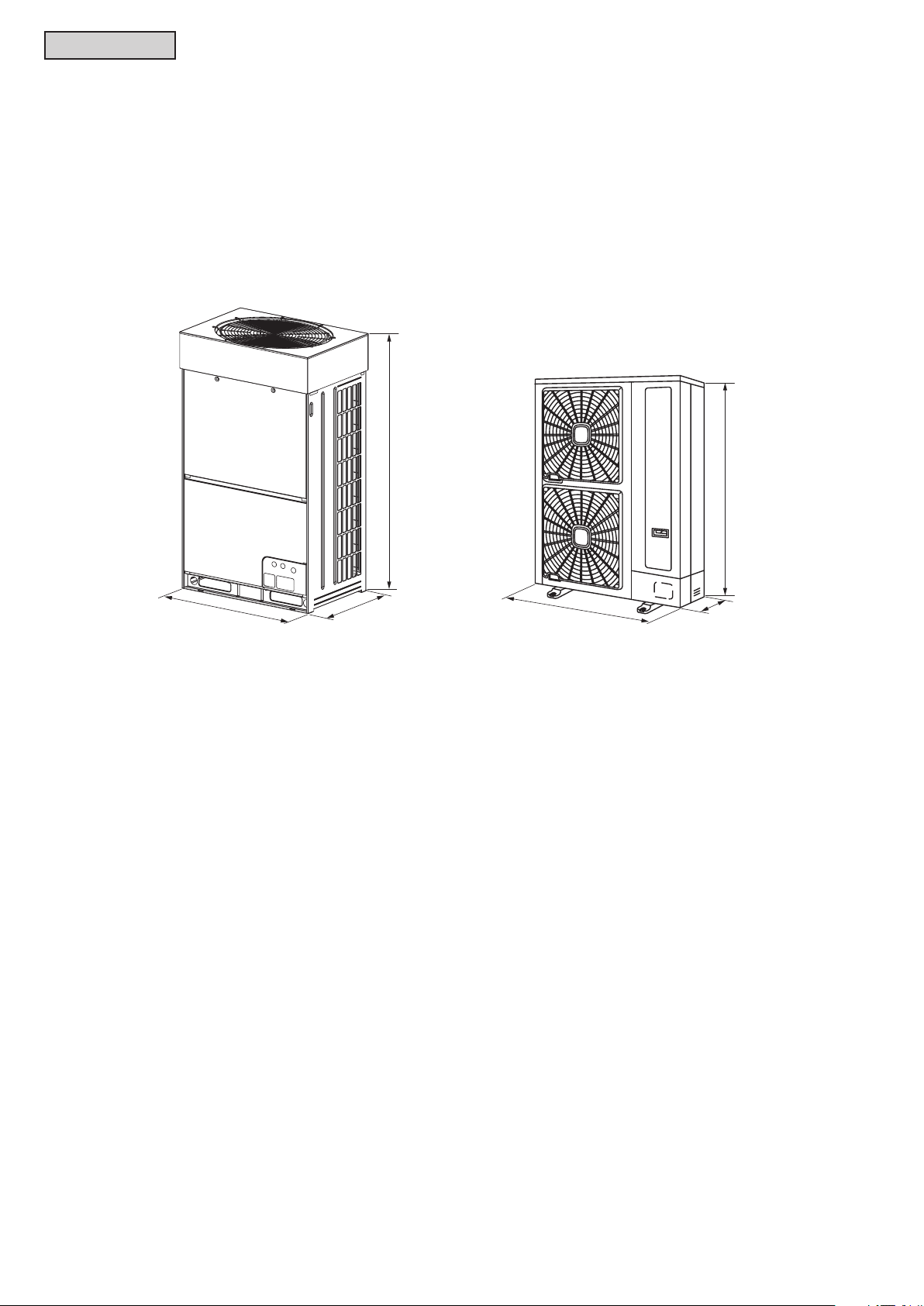
Compact and Lightweight Design
l
Facilitation and exibility at installation are further advanced by adopting a lightweight and compact design
of the outdoor unit compared to a top-ow model.
< For Example: Comparing (H,Y,C)VAHP048B21S and (H,Y,C)VAHP096B21S >
* Floor Area per Nominal Capacity:
* Net Weight per Nominal Capacity:
48-1/8 in.
32% Decrease
27% Decrease
68-1/8 in.
31-1/4 in.
37-3/8 in.
14-9/16 in.
Net Weight =
Nominal Capacity = 96,000 Btu/h Nominal Capacity = 48,000 Btu/h
730 lbs
(331kg) (113kg)
Net Weight =
249 lbs
● With a width of only 14-9/16 in. (370mm), a Mini VRF can be installed on a staircase landing or balcony
on each oor. (Regarding service space, refer to Section 2.7 “Service Space”.)
● Side-ow type Mini VRF can be installed under the eaves.
● With its light and compact body, Mini VRF can be easily carried in the elevator site.
(No cranes required for delivery.)
● The Mini VRF can be transported by as few as two people.
1-4
TC-16001-rev.5
Page 15
FEATURES
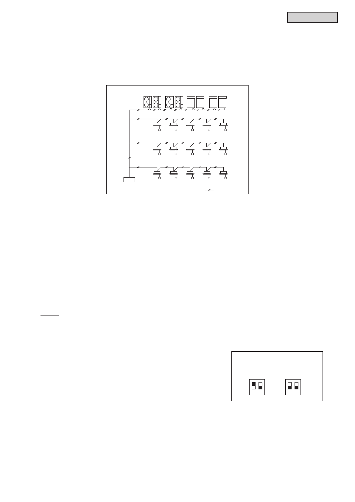
< System Example >
Corresponds to H-LINK II System
l
The outdoor units in the VRF Series correspond to the H-LINK II communication system. A maximum
of 64 refrigerant groups and a maximum of 160 indoor units can be controlled by only one central
control device when the equipment (central control device, indoor units, wired controller) in the same
communication system all correspond to H-LINK II.
Outdoor Units (Max. 64 Refrigerant Group)
Indoor Units (
Max. Connectable Q'ty: 160)
H-LINK II System
l
The H-LINK II wiring system requires only two communication cables to connect each indoor unit and
<Specications>
* Communication Cable: 2-Wire
* Polarity of Communication Cable: Non-Polar Cable
* Maximum Outdoor Units to be Connected: 64 Units per System
* Maximum Indoor Units to be Connected: 160 Units per H-LINK II System
* Maximum Cable Length: Total 3,280 ft. (1,000m) (including central controller)
* Recommended Cable: Communication Cable with Shield, over AWG18 (Equivalent to KPEV-S)
* Voltage: DC5V
NOTE:
When using an H-LINK II system, the setting of DIP switches for an outdoor unit and indoor unit is required.
If the DIP switches are not set, or set incorrectly, an alarm may occur because of a communication failure.
Setting of End Terminal Resistance
l
Factory setting of the No.1 pin of DSW5 is in the "ON" position.
Central Control Device
: Control Line
outdoor unit for up to 64 refrigerant systems, and to connect wires for all indoor units and outdoor units.
Setting of End Terminal Resistance
When the number of outdoor units in the same H-LINK system is
two or more, set the No.1 pin of DSW5 at "OFF" at the second unit.
If only one outdoor unit is used, no setting is required.
Factory Setting Cancellation
DSW5
ON
OFF
12 12
ON
OFF
TC-16001-rev.5
1-5
Page 16

FEATURES
Indoor Air Inlet Temperature oF DB/WB (oC DB/WB)
Outdoor Air Temperature
Indoor Air Inlet Temperature oF DB (oC DB)
Outdoor Air Temperature
Wide Operation Range
l
This unit has been designed for cooling operations under low ambient temperatures down to
23°F (-5°C) DB.
This wide operation range enables cooling even in winter in buildings with high internal heat gains
resulting from lighting, people and machines, particularly in areas such as shops, lecture rooms, and data
processing areas Heating operations under low ambient temperature down to -4°F (-20°C) WB can also
be accomplished.
Cooling Operation
118(48)
C DB)
o
F DB (
o
50(10)
23(-5)
Continuous Operation
Working Range
70/59
(21/15)
90/74
(32/23)
NOTE:
For details, please refer to Section 2.12 “Operation Range”.
C WB)
o
F WB (
o
59(15)
5(-15)
-4(-20)
Heating Operation
Continuous Operation
Working Range
Operation
Working Range
-9.5
(15)
80
(27)
1-6
TC-16001-rev.5
Page 17

FEATURES
Operating Hours
Power Consumption
the reference power consumption
Power Setting
8 A.M. 12 P.M. 3 P.M. 6 P. M.
Time
Group A Group B
The specific outdoor unit and the period of time can be set from
computerized controller.
Computerized Controller
(
Energy-Saving through Schedule Setting of “Self-Demand Function”
l
“Self-Demand Function”* can be set for each outdoor unit from a Computerized Central Controller (CCCS01
and CCCA01) or Wired Controller (CIW01).
For small and medium buildings, it facilitates power saving. The energy-saving operation can be adjusted
conforming to an operating environment and individual needs.
* Self-Demand Function: It saves capacity so as not to exceed demand current control based on
the electric power data detected.
< Self-Demand Function >
Excessive power usage exceeding
the setting range is restricted.
Power Setting
Selectable from 100%,
Maximum efficiency is secured
within the power setting range.
Morning Daytime Night
80%, 70%, 60% and 40% of
for cooling operation.
Outdoor Unit Capacity
[MBH]
Reference Power Consumption
[kW]
036 3.9
048 4.5
060 4.5
< Setting Example: Schedule Setting for Each Group by Computerized Controller >
Group A
Group B
Power Setting: 60%
Power Setting: 80%
Various operating methods
are available depending on
purpose and needs.
CCCS01 and CCCA01)
NOTES:
1. The demand current control (%) is indicated by approximate values. The value in this control which is
calculated by the current is different from the value in the wattmeter.
If it is required that the maximum power consumption is managed precisely, a eld-supplied demand
controller should be used.
2. The range may temporarily be higher than the power-setting range (%) depending on the operating
control condition such as protection control.
3. When the above self-demand control is set, performance is restricted because the rotation frequency of
the compressor is automatically lowered.
TC-16001-rev.5
1-7
Page 18

FEATURES
Operation Sound Reduction Function
l
(1) Night Shift Mode (Optional Function)
With the Night Shift Mode setting by optional function, when ambient temperature is 86
less in a cooling operation, rotation speed of the compressor and the outdoor fan is automatically
lowered.
o
F (30oC) or
Outdoor Unit Capacity
[MBH]
036 51 44
048 52 46
060 53 46
Sound Pressure Level [dB]
Rated Operation Night Shift
NOTES:
1. Night shift mode is recommended when cooling capacity has sufcient margin compared to cooling
load and operation sound should be reduced at night time.
2. Cooling capacity may be decreased about 60%.
3. Regarding setting methods, refer to the Service Manual.
(2) Low Noise Setting Mode (Optional Function)
With Low Noise Setting Mode by optional function, rotation speed of the compressor is forcibly
decreased regardless of ambient temperature.
Low Noise Setting Mode can be selected from three levels and time can be scheduled and set by the
Wired Controller (CIW01).
Outdoor Unit Capacity
[MBH]
036 -1 -2 -3
048 -1 -2 -3
060 -2 -3 -4
Low Noise Setting 1 Low Noise Setting 2 Low Noise Setting 3
Sound Pressure Level [dB]
NOTES:
1. Cooling and heating capacity may drop to 80%, 70% and 60% in each setting mode.
2. Regarding setting method, refer to the Service Manual.
3. Regarding time schedule setting, refer to the Installation Manual for the Wired Controller.
1-8
TC-16001-rev.5
Page 19

2. Outdoor Units
2.1 Unit Nomenclature
● Outdoor Units
Model Descriptions
Example
Nomenclature Description
H = Hitachi Brand
Y = York Brand
C = Coleman Brand
VRF V
A = Air Source A
HP = Heat Pump HP
036 = 36 MBH
048 = 48 MBH
060 = 60 MBH
B = R410A B
2 = 208/230Volts - 1Phase - 60Hz 2
1 = 1st Generation 1
S = Standard (Factory Options) S
OUTDOOR UNITS
H V A HP 036 B 2 1 S
H
036
2.2 Line-up
Voltage Capacity (MBH) Model Name
208/230V
TC-16001-rev.5
2-1
36 (H,Y,C)VAHP036B21S
48 (H,Y,C)VAHP048B21S
60 (H,Y,C)VAHP060B21S
Page 20

OUTDOOR UNITS
2.3 General Data
Category Mini VRF Outdoor Unit
Model (H,Y,C)VAHP036B21S (H,Y,C)VAHP048B21S (H,Y,C)VAHP060B21S
Power Supply 208/230V/ 1PH 60Hz 208/230V/ 1PH 60Hz 208/230V/ 1PH 60Hz
Capacity (Nominal) *1
Efficiency Ratings *2
(Non-Ducted / Ducted)
Cooling Operating
Range
Heating Operating
Range
Cabinet Color (Munsell Code) - 1.0Y8.5/0.5 1.0Y8.5/0.5 1.0Y8.5/0.5
Outer Dimensions
Package Dimensions
Weight
Connection Ratio
Heat Exchanger
Compressor
Crank Case Heater W × Qty 52W(208V) ×1 52W(208V) ×1 52W(208V) ×1
Fan
Electrical
Sound Pressure Level
*5
Protection Devices
Refrigerant
Refrigeration Oil Charge Amount gal/Unit (L/Unit) 0.34 (1.3) 0.34 (1.3) 0.34 (1.3)
Defrost Method - Reversed Refrigerant Cycle Reversed Refrigerant Cycle Reversed Refrigerant Cycle
Main Refrigerant
Piping
Cooling Capacity (Nominal) Btu/h (kW) 36,000 (10.6) 48,000 (14.1) 60,000 (17.6)
Heating Capacity (Nominal) Btu/h (kW) 40,000 (11.7) 54,000 (15.8) 64,000 (18.8)
Cooling
Heating
Indoor
Outdoor
Indoor
Outdoor
Height in. (mm) 54-5/16 (1380) 54-5/16 (1380) 54-5/16 (1380)
Width in. (mm) 37-3/8 (950) 37-3/8 (950) 37-3/8 (950)
Depth in. (mm) 14-9/16 (370) 14-9/16 (370) 14-9/16 (370)
Height in. (mm) 59-9/16 (1513) 59-9/16 (1513) 59-9/16 (1513)
Width in. (mm) 40-3/8 (1025) 40-3/8 (1025) 40-3/8 (1025)
Depth in. (mm) 18-1/8 (460) 18-1/8 (460) 18-1/8 (460)
Net lbs (kg) 249 (113) 249 (113) 249 (113)
Gross lbs (kg) 267 (121) 267 (121) 267 (121)
Total Indoor Unit Capacity % 130-60 130-60 105-60
Max. Indoor Units/System - 6 8 8
Type -
Material - Cu-Al (Anti-corrosion) Cu-Al (Anti-corrosion) Cu-Al (Anti-corrosion)
Type - HA36PHD-A1S2 HA36PHD-A1S2 HA36PHD-A1S2
Motor Phase / Pole - / - 3PH / 6 3PH / 6 3PH / 6
Start Method - Inverter Inverter Inverter
Operation Range % 10 ~ 100 10 ~ 100 10 ~ 100
Refrigeration Oil Type - FVC68D FVC68D FVC68D
Type - Propeller Fan Propeller Fan Propeller Fan
Quantity Qty 2 2 2
Motor Output (Pole) W (Pole) 58(10) + 58(10) 58(10) + 58(10) 58(10) + 58(10)
Airflow Rate cfm
Drive - Direct-drive Direct-drive Direct-drive
Min. Circuit Amps A 31 31 31
Max. Overcurrent Protective Device A 40 40 40
Cooling (Night-Shift) dB (A) 51 (44) 52 (46) 53 (46)
Heating dB (A) 52 54 56
Cycle -
Compressor -
Fan Motor -
PCB (Control Circuit) Type - R410A R410A R410A
Charge Amount lbs (kg) 7.9 (3.6) 7.9 (3.6) 7.9 (3.6)
Gas Line in. (mm) 5/8 (15.88) 5/8 (15.88) 5/8 (15.88)
Liquid Line in. (mm) 3/8 (9.52) 3/8 (9.52) 3/8 (9.52)
Power Input kW 2.53 3.78 5.05
Current Input A (208V/230V) 12.3 / 11.1 18.6 / 16.9 24.8 / 22.4
Power Input kW 2.36 3.95 4.42
Current Input A (208V/230V) 11.8 / 10.6 19.6 / 17.7 21.7 / 19.6
Rated Capacity Btu/h 36,000 / 36,000 48,000 / 48,000 60,000 / 55,000
EER Btu/Wh 16.70 / 13.80 16.70 / 13.10 12.20 / 9.70
SEER Btu/Wh 23.50 / 18.70 24.10 / 18.40 16.80 / 15.90
Rated Capacity Btu/h 40,000 / 40,000 54,000 / 54,000 64,000 / 64,000
COP W/W 5.12 / 3.90 4.56 / 3.86 3.90 / 3.30
HSPF Btu/Wh 12.80 / 11.00 11.70 / 11.80 12.10 / 10.60
o
F WB (oC WB)
o
F DB (oC DB)
o
F DB (oC DB)
o
F WB (oC WB)
(m
23 (-5) ~ 118 (48) *3 23 (-5) ~ 118 (48) *3 23 (-5) ~ 118 (48) *3
-4 (-20) ~ 59 (15) *4 -4 (-20) ~ 59 (15) *4 -4 (-20) ~ 59 (15) *4
3
3177 (90) 3530 (100) 3530 (100)
/min)
High pressure switch
at 601psi (4.15MPa)
Over-current protection
Over-heat protection
Circuit Breaker (30A)
Over-current protection
Over-heat protection
Self-contained fuse (5A)
59 (15) ~ 73 (23) 59 (15) ~ 73 (23) 59 (15) ~ 73 (23)
59 (15) ~ 80 (27) 59 (15) ~ 80 (27) 59 (15) ~ 80 (27)
Multi-Pass Cross-
Finned Tube
Fuse on PCB(5A)
Multi-Pass Cross-
Finned Tube
High pressure switch
at 601psi (4.15MPa)
Over-current protection
Over-heat protection
Circuit Breaker (30A)
Over-current protection
Over-heat protection
Self-contained fuse (5A)
Fuse on PCB(5A)
Multi-Pass Cross-
High pressure switch
at 601psi (4.15MPa)
Over-current protection
Over-heat protection
Circuit Breaker (30A)
Over-current protection
Over-heat protection
Self-contained fuse (5A)
Fuse on PCB(5A)
Finned Tube
NOTES:
*1 Rating Conditions:
Cooling Heating
Indoor Air Inlet Temperature: 80
67
Outdoor Air Inlet Temperature: 95
o
F (26.7oC) DB Indoor Air Inlet Temperature: 70oF (21.1oC) DB
o
F (19.4oC) WB Outdoor Air Inlet Temperature: 47oF (8.3oC) DB
o
F (35.0oC) DB 43oF (6.1oC) WB
Piping Length: 24.6ft. (7.5m), Piping Lift: 0ft. (0m)
*2 Efciency ratings are based on the AHRI 210/240 test standard.
*3 There are some exceptions and notes for cooling operation ranges. For details, refer to Section 2.12 “Operation Range”.
*4 There are some exceptions and notes for heating operation ranges. For details, refer to Section 2.12 “Operation Range”.
*5 Measurement Point: 3.3ft. (1m) from the air outlet side, 4.9ft. (1.5m) from oor level.
The operation sound is measured in an anechoic chamber. However, the actual operation sound may appear louder or with an echo
because of surrounding environmental noise. Be sure to check environmental conditions before installation.
The sound of the air inlet side may be 3dB higher than that of the air outlet side.
2-2
TC-16001-rev.5
Page 21

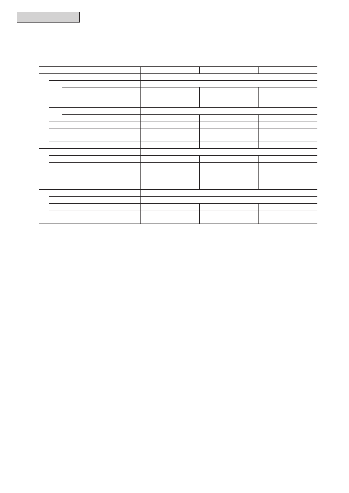
2.4 Dimensional Data and Weights
2.4.1 Overall Dimensional and Weight Data
OUTDOOR UNITS
Model
(H,Y,C)VAHP036B21S
(H,Y,C)VAHP048B21S
(H,Y,C)VAHP060B21S
Height
[in. (mm)]
54-5/16
(1380)
54-5/16
(1380)
54-5/16
(1380)
Width
[in. (mm)]
37-3/8
(950)
37-3/8
(950)
37-3/8
(950)
Depth
[in. (mm)]
14-9/16
(370)
14-9/16
(370)
14-9/16
(370)
Net Weight
[lbs (kg)]
249
(113)
249
(113)
249
(113)
TC-16001-rev.5
2-3
Page 22

OUTDOOR UNITS
2.4.2 Outdoor Units
Model: (H,Y,C)VAHP036B21S to (H,Y,C)VAHP060B21S
inch [mm]
A side view
•
Drain Water
Drain water is caused during heating operation or defrost operation.
1
Choose a place where well drainage is available.
Or provide a groove for drain.
2
Do not provide an upward slope from the unit
to avoid reverse ow of the drain.
3
When dripping drain water is not permissible,
provide a second drain pan under the outdoor unit to
ensure collection of drain water.
2-4
TC-16001-rev.5
Page 23

2.5 Structure
Model: (H,Y,C)VAHP036B21S to (H,Y,C)VAHP060B21S
OUTDOOR UNITS
inch [mm]
No. Part Name
1 Compressor (Inverter)
2 Heat Exchanger
3 Propeller Fan (2 pcs.)
4 Fan Motor (2 pcs.)
5 Strainer (2 pcs.)
6 Distributor
7 Reversing Valve
8 Electronic Expansion Valve
9 Solenoid Valve
10 Stop Valve (Gas)
11 Stop Valve (Liquid)
TC-16001-rev.5
2-5
No. Part Name
12 Check Valve
13 Accumulator
14 Access Port
15 Oil Separator
16 Capillary Tube
17 Electrical Control Box
18 High Pressure Switch for Protection
19 High Pressure Sensor
20 Low Pressure Sensor
21 Crankcase Heater
22 Vibration Absorber (4 pce.)
Page 24
OUTDOOR UNITS
222
222
EEE
222
2.6 Component Data
Outdoor Heat Exchanger and Fan
Model
Heat Exchanger Type
Tube Material Copper Tube
Outer Diameter
Rows
Number of Tube/Coil
Fin Material Aluminum
Pitch in. (mm) 0.055 (1.4) 0.055 (1.4) 0.055 (1.4)
Maximum Operating Pressure
Total Face Area 14.42 14.42 14.42
Number of Coil/Unit 1 1 1
Outdoor Fan
Number/Unit
Outer Diameter
Nominal Airflow cfm
Outdoor Fan Motor
Starting Method DC Motor
Nominal Output W
Quantity
Insulation Class
in. (mm)
psi (MPa) 601 (4.15) 601 (4.15) 601 (4.15)
2
ft
(m2)
in.
(mm)
3
/min)
(m
(H,Y,C)VAHP036B21S (H,Y,C)VAHP048B21S (H,Y,C)VAHP060B21S
Multi-Pass Cross Finned Tube
0.28 (7.0) 0.28 (7.0) 0.28 (7.0)
132 132 132
(1.34) (1.34) (1.34)
Large Diameter Fan (Propeller Fan)
21-7/16 21-7/16 21-7/16
(544) (544) (544)
3496 3885 3885
(99) (110) (110)
Drip-Proof Type Enclosure
58+58 58+58 58+58
2-6
TC-16001-rev.5
Page 25

OUTDOOR UNITS
inch (mm)
inch (mm)
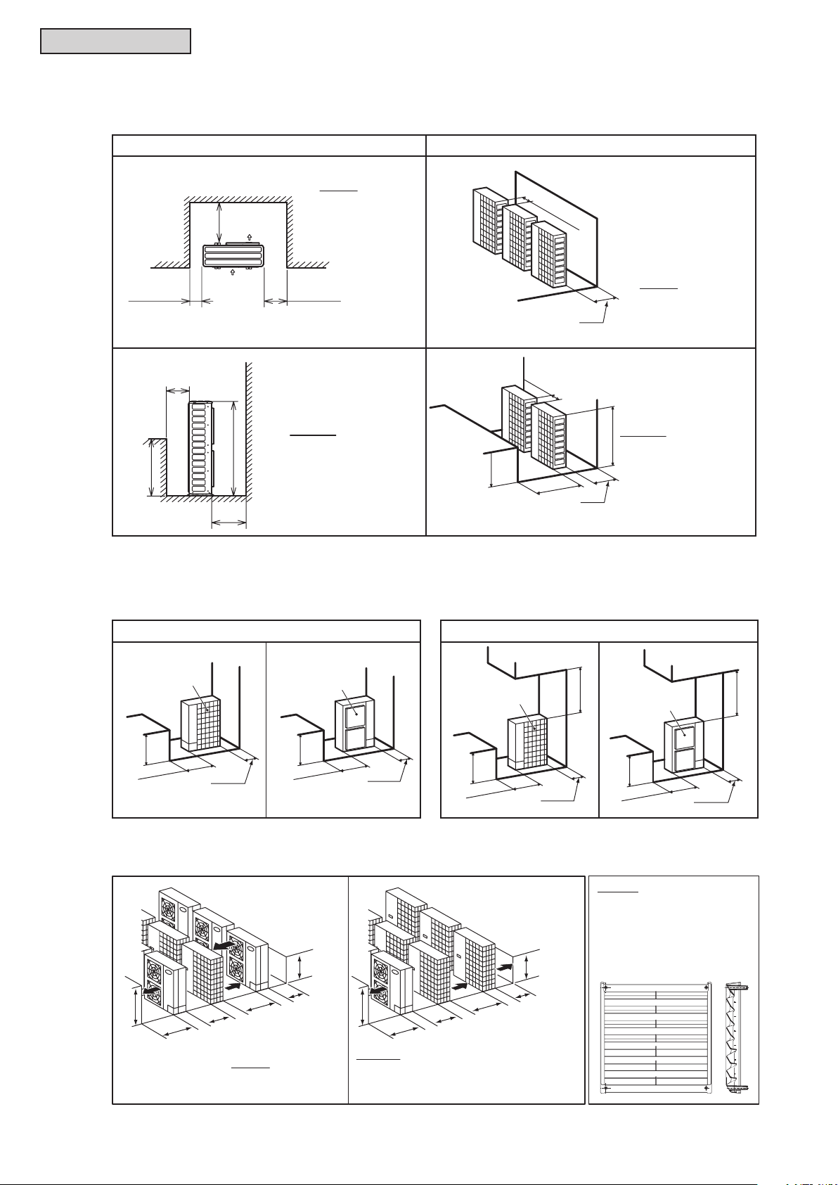
2.7 Service Space
When an outdoor unit is installed, allow sufcient clearance as follows:
•If there is insufcient clearance for air inlets and outlets, it may result in a performance drop-off and
mechanical issues due to insufcient air intake.
•Additionally, adequate clearance is required for service maintenance access.
(1) Obstacles on Inlet Side
(a) Upper Side is Open.
Single Installation Multiple Installation
* Around sides
are open.
Min. 8 (200)
Front Side
* Around sides
are closed.
Min. 2
(50)
Fit positions " " with unit front side.
NOTES:
A
● Install Airflow Guide
(optional)
● Open both
right and left sides.
H
L
B
(b) Obstacles on Upper Side
Min. 12 (300)
Front
Side
Min. 4
(100)
Min. 12 (300)
Front Side
Min. 4
(100)
NOTE:
Open both right and left sides.
Min. 4
(100)
L
A
B
Front Side
NOTES:
● Install Airflow Guide
(optional)
● Open both
right and left sides.
Max. 12 (300)
Max. 12 (300)
A
L
B
Single Installation Multiple Installation
Min. B
Min. 40
(1000)
H
Min. 40
(1000)
H
NOTES:
● Install Airflow Guide
(optional)
● Open both
right and left sides.
Min. 4 (100)
Min. 4 (100)
L
Max. 12 (300)
B
Max. 12 (300)
A
B
(1000)
Min. 40
NOTE:
Open both
H
right and left sides.
(1000)
Min. 40
NOTES:
● Install Airflow Guide
(optional)
H
● Open both
right and left sides.
● No more than 2 units
for multiple installation
TC-16001-rev.5
2-7
Page 26
OUTDOOR UNITS
inch (mm)
inch(mm)
inch (mm)
inch (mm)
(2) Obstacles on Outlet Side
(a) Upper Side is Open.
Single Installation Multiple Installation
Front
A
Side
Min. 2 (50)Min. 4 (100)
B
NOTES:
H
L
● Install Airflow Guide
(optional)
● Open both
right and left sides.
A
(3) Obstacles on Right and Left Side
NOTE:
Open eather
right or left side.
Min. 4 (100)
NOTE:
Open both
A
Min. 6 (150)
L
B
A
right and left sides.
NOTES:
H
● Install Airflow Guide
(optional)
● Open both
right and left sides.
● No more than 2 units
for multiple installation
(a) Upper Side is Open. (b) Obstacles on Upper Side
L
Min. 20
(500)
Rear Side
Single Installation
L
Min. 2
(50)
Min. 20
(500)
Front Side
Min. 4
(100)
L
Min. 20
(500)
Rear Side
Single Installation
Min. 2
(50)
(4) Multi-Row and Multiple Installations
L
A
(4000)
(3000)
L
B
L
Min. 24
A
Min. 158
(600)
NOTES:
● Open both right and left sides.
● Install each outdoor unit not to inlet
the outlet air from the other outdoor units.
L
A
Min. 119
Min. 24
(600)
NOTE:
Open both
right and left sides.
(1000)
Min. 40
Front Side
L
Min. 20
(500)
Min. 4
NOTE:
Ensure that the outlet
ow is not short-circuited
to the air inlet side when
using the Airow Guide
(optional).
(100)
(1000)
Min. 40
2-8
TC-16001-rev.5
Page 27

OUTDOOR UNITS
NOTE
inch (mm)
• If L is larger than H, mount the units on a base so that H
is greater or equal to L.
Be sure to seal up every surface of the base. If the base
allows the airow to go, it may cause a short-circuit.
• The Airow Guide (optional) is required when there are interferences in both the front and rear side of the
outdoor unit.
• The installation of multi-row and multiple outdoor units should be up to three outdoor units on a roof. Use
the Airow Guide (optional) in order to prevent short-circuiting if more than three outdoor units are installed.
L A B
0 < L < 1/2H
1/2H < L < H
24 (600)
or more
56 (1400)
or more
12 (300)
or more
14 (350)
or more
TC-16001-rev.5
2-9
Page 28

OUTDOOR UNITS
2.8 Center of Gravity
Model
(H,Y,C)VAHP036B21S
(H,Y,C)VAHP048B21S
(H,Y,C)VAHP060B21S
Model
(H,Y,C)VAHP036B21S 44
(H,Y,C)VAHP048B21S 54
(H,Y,C)VAHP060B21S 74
Net Weight
[lbs (kg)]
249
(113)
249
(113)
249
(113)
Frequency
of Vibration
[Hz]
Center of Gravity
[inch (mm)]
a b c
23-5/8
(600)
23-5/8
(600)
23-5/8
(600)
Amplitude Value [×10
1 2 3 4 1 2 3 4
0.04
(1)
0.04
(1)
0.04
(1)
7-1/16
7-1/16
7-1/16
0.04
(1)
0.04
(1)
0.04
(1)
(180)
(180)
(180)
24-7/16
(620)
24-7/16
(620)
24-7/16
(620)
-3
inch (μm)] Acceleration of Vibration [dB]
0.08
(2)
0.08
(2)
0.08
(2)
0.04
(1)
0.04
(1)
0.04
(1)
72 72 78 72
75 75 81 75
81 81 87 81
< Vibration Characteristics Measurement Conditions >
Above values are measured under the following conditions:
1. Outdoor unit is placed on a concrete oor 5 in (120mm) thick (concrete oor is directly cast on ground).
2. Outdoor unit is operated under our standard operating conditions.
2-10
TC-16001-rev.5
Page 29

OUTDOOR UNITS
2.9 Electrical Data
Outdoor Unit INV Comp.
Model
(H,Y,C)VAHP036B21S 60 208/230 228/253 188/207 31 40 40 24 30
(H,Y,C)VAHP048B21S 60 208/230 228/253 188/207 31 40 40 24 30
(H,Y,C)VAHP060B21S 60 208/230 228/253 188/207 31 40 40 24 30
Model
(H,Y,C)VAHP036B21S 0.058+0.058 0.5+0.5 8 8 18 3/4 (19.05)
(H,Y,C)VAHP048B21S 0.058+0.058 0.5+0.5 8 8 18 3/4 (19.05)
(H,Y,C)VAHP060B21S 0.058+0.058 0.5+0.5 8 8 18 3/4 (19.05)
MCA: Minimum Circuit Ampacity (A)
MOP: Maximum Overcurrent Protective Device (A)
RLA: Rated Load Ampacity (A)
LRA: Locked Rotor Ampacity (A)
FLA: Full Load Ampacity (A)
Hz Voltage Max. Min. MCA MOP Max. Fuse RLA LRA
[Hz] [V] [V] [V] [A] [A] [A] [A] [A]
Fan Motor Wiring Size Conduit Tube
Output FLA
[kW] [A] [AWG] [AWG] [AWG] [in. (mm)]
Power Supply
Wiring
Ground Wiring
Communication
Cable
for Power
Supply Wiring
TC-16001-rev.5
2-11
Page 30

OUTDOOR UNITS
2.10 Sound Data
Model: (H,Y,C)VAHP036B21S
Octave Band Central Frequency [Hz]
63 125 250 500 1k 2k 4k 8k
Cooling 32.4 33.5 40.8 47.0 46.1 41.5 36.6 23.1 51
Cooling (Night Shift) 29.9 27.4 34.6 41.8 33.4 31.2 32.7 22.8 44
Heating 53.7 52.9 49.9 50.6 47.0 42.5 37.0 31.9 52
Overall
[dB(A)]
Model: (H,Y,C)VAHP048B21S
Octave Band Central Frequency [Hz]
63 125 250 500 1k 2k 4k 8k
Cooling 32.1 33.1 40.9 47.3 47.6 43.6 38.9 26.9 52
Cooling (Night Shift) 29.9 29.3 36.3 44.1 34.6 32.9 34.6 24.8 46
Heating 32.1 36.9 42.9 48.8 49.3 45.8 44.0 29.9 54
Overall
[dB(A)]
Model: (H,Y,C)VAHP060B21S
Octave Band Central Frequency [Hz]
63 125 250 500 1k 2k 4k 8k
Cooling 33.1 34.1 42.0 48.3 48.6 44.6 39.9 27.9 53
Cooling (Night Shift) 29.9 29.3 36.3 44.1 34.6 32.9 34.6 24.8 46
Heating 30.0 37.9 45.3 51.8 49.8 47.9 46.7 33.1 56
Overall
[dB(A)]
NOTE:
The operation sound is measured in an anechoic chamber. However, the actual operation sound may appear louder because
of ambient noise or echoing. Be sure to check ambient conditions before installation.
The sound of the air inlet side may be 3dB higher than that of the air outlet side.
2-12
TC-16001-rev.5
Page 31

2.11 Control System
2.11.1 Refrigerant Cycle
Model: (H,Y,C)VAHP036B21S to (H,Y,C)VAHP060B21S
OUTDOOR UNITS
TC-16001-rev.5
Access Port
2-13
Page 32

OUTDOOR UNITS
2.11.2 Control System
Cycle Control
No. Item Details
Comp. Frequency Control
I.U. Electronic Exp. Valve Control
Cooling
1
Operation
Heating
2
Operation
Defrost
3
Operation
4 Comp. Preheating Control Crankcase Heater Control
O.U. Electronic Exp. Valve Control EVO: 480pls (Fully Opened)
Outdoor Fan Control
Reversing Valve Control Reversing Valve: OFF
Control of Solenoid Valve for
High/Low Pressure Bypass (SVA)
High/Low Pressure Control SVA: ON (during Operation Stop)
Comp. Frequency Control
I.U. Electronic Exp. Valve Control
O.U. Electronic Exp. Valve Control
Outdoor Fan Control
Reversing Valve Control Reversing Valve: ON
Control of Solenoid Valve for
High/Low Pressure Bypass (SVA)
High/Low Pressure Control SVA: ON (during operation stop)
Comp. Frequency Control Fixed Compressor Frequency
I.U. Electronic Exp. Valve Control
O.U. Electronic Exp. Valve Control EVO: 480pls (Fully Opened)
Outdoor Fan Control To stop the outdoor fan.
Reversing Valve Control Reversing Valve: OFF
Control of Solenoid Valve for
High/Low Pressure Bypass (SVA)
To determine the compressor frequency depending on (a),
(b) and (c).
● Quasi PI Control:
To determine the I.U. electronic expansion valve opening
so as to keep (d) at an optimum value.
● To change the I.U. electronic expansion valve opening
when the number of operating indoor units is changed.
To control the fan steps so that High Pressure is within a
stable temperature range.
At Start-up and when High Pressure Increase Protection
activated: ON
● PI Control:
To determine the compressor frequency so as to keep
High Pressure.
● To determine the compressor frequency from (a) and
(c) when heating operation is started or the number of
operating indoor units is changed.
● To determine the I.U. electronic expansion valve opening
so that the indoor liquid pipe temperature (trl) is at an
optimum level.
● To change the I.U. electronic expansion valve opening
when the number of operating indoor units is changed.
● Quasi PI Control:
To determine the O.U. electronic expansion valve
opening so as to keep the temperature at the top of the
compressor at an optimum level.
● When Operating Indoor Unit Number Changed:
To determine the O.U. electronic expansion valve
opening from the compressor frequency ratio before/after
the change and Quasi PI Control.
The fan steps are dependent on Ta in the beginning. After
that to control the fan steps so that Pd is within a stable
pressure range.
At Start-up and when High Pressure Increase Protection
activated: ON
To determine the I.U. electronic expansion valve opening
depending on the temperature at the top of the compressor
(Td).
at Start-up: ON
(a): Difference between Indoor Inlet Air Temperature and Setting Temperature
(b): Amount of Temperature Difference Change
(c): Capacity Ratio between Operating Indoor Unit and Outdoor Unit
(d): Temperature Difference between Indoor Gas Pipe and Indoor Liquid Pipe
(= Indoor Gas Pipe Temperature - Indoor Liquid Pipe Temperature)
2-14
TC-16001-rev.5
Page 33

only for Decorative Panel
I.U. : Indoor Unit
2.11.3 Standard Operation Sequence
Cooling Operation
n
Power to
O.U.: ON
Power to
I.U.: ON
Set
Operation Mode
to “COOL”
Power to
O.U. PCB: ON
Power to
I.U. PCB: ON
Power to YH2
in I.U.: OFF
FS
ON
(Lower than
Activation Level)
Temp. at Top
of Compressor
o
F (30oC)
< 86
or
< Outdoor Temperature +45
o
> 86
F (30oC)
and
> Outdoor Temperature +45
Auto-Louver
0 Reset
OFF
(Higher than
Activation Level)
only for indoor unit
with auto-louver
Power to YH2 in
I.U.: ON
o
F (+25oC)
o
F (+25oC)
OUTDOOR UNITS
O.U. : Outdoor Unit
: Actuator (refer to Ta ble 2.1)
Power to CH : ON
Power to CH : OFF
Start of Communication between
O.U. and I.U.
Start of Communication between
I.U. and Wired Controller
MD Operation: ON
for unit with drain pump
“COOL” Indication
Press
Fan Speed
Switch
Press
Temp. Setting
Switch
Press
RUN/STOP
Switch
Cooling
Operation
HIGH
(HIGH 2)
Fan Speed
Switch
LOW
Power to YH2 for 20 sec.
I.U. Air
Inlet
Temp.
< Set Temp.
MED
> Set Temp.
< 23
Outdoor
Temp.
o
F (-5oC)
Switch: To increase Set Te mp.
Switch: To Decrease Set Te mp.
o
> 23
F
(-5oC)
Power to
Y52C :
ON
Power to
CMC :
ON
Elapsed Time:
1sec.
No
“HIGH (HIGH 2)”
“LOW” Indication
Run Indicator: ON
MIF Operation at
Set Fan Speed
Yes
Power to
YH2 : ON
for unit with drain pump
Indication
“MEDIUM”
Indication
Indication
of Set Temp.
MC Operation: ON
MOF Operation: ON
MD Operation: ON
Press
AUTO-LOUVER
Switch
to 1
TC-16001-rev.5
Start of
Auto-Louver
< Alternately >
Stop of
Auto-Louver
or Indoor Unit
with Auto-Louver
2-15
Page 34

OUTDOOR UNITS
I.U. : Indoor Unit
able 2.1)
Cooling Operation
n
1
Press
RUN/STOP
Switch
STOP
Temp. at Top
of Compressor
MOF Operation: OFF
No
Elapsed Time:
1 min. 20 sec.
< 77oF (25oC)
or
< Outdoor Temperature +36
o
> 86
and
> Outdoor Temperature +45
Power to Y52C : OFF
Yes
O.U. : Outdoor Unit
: Actuator (refer to T
Inverter: OFF
MC Operation: OFF
o
F (+20oC)
F (30oC)
o
F (+25oC)
RUN Indicator: OFF,
COOL, Set Fan Speed & Set Temp. Indications: Continuously ON
Power to CH : ON
Power to CH : OFF
Power to CMC : OFF
MD Operation: OFFPower to YH2 : OFF
for unit with drain pump
MIF Operation: OFF
Power to
I.U.: OFF
Power to
O.U.: OFF
Power to I.U. PCB: OFF
Power to O.U. PCB: OFF
LCD Indication: OFF
Power to CH : OFF
2-16
TC-16001-rev.5
Page 35

Dry Operation
only for Decorative Panel
I.U. : Indoor Unit
n
Power to
O.U.: ON
Power to
I.U.: ON
Set
Operation Mode
to “DRY”
Power to
O.U. PCB: ON
Power to
I.U. PCB: ON
Power to YH2
in I.U.: OFF
Temp. at Top
of Compressor
FS
ON
(Lower than
Activation Level)
Auto-Louver
0 Reset
OFF
(Higher than
Activation Level)
< 86oF (30oC)
or
< Outdoor Temperature +45
o
> 86
F (30oC)
and
> Outdoor Temperature +45
only for indoor unit
with auto-louver
Power to YH2
in I.U.: ON
o
F (+25oC)
o
F (+25oC)
OUTDOOR UNITS
O.U. : Outdoor Unit
: Actuator (refer to Table 2.1)
Power to CH : ON
Power to CH : OFF
Start of Communication between
I.U. and O.U.
Start of Communication between
I.U. and Wired Controller
MD Operation: ON
for unit with drain pump
“DRY” Indication
Press
TEMP. Setting
Switch
Press
RUN/STOP
Switch
Dry Operation
Power to YH2 : ON
I.U. Air
Inlet
Temp.
< Set Temp.
> Set Temp.
< 23
Outdoor
Temp.
o
F (-5oC)
Switch: To increase Set Te mp.
Switch: To decrease Set Te mp.
MIF Operation at Low Fan Speed
> 23oF
(-5oC)
Power to
Y52C :
ON
Indication of Set Temp.
RUN Indicator: ON
Elapsed Time:
1sec.
No
Power to MC : OFF
Power to MIF : OFF
MIF Operation at Low Fan Speed
Yes
Elapsed Time:
6 min.
Yes
Power to MC :ON
MOF Operation
: ON
No
Elapsed Time:
6 min.
Yes
No
Press
AUTO-LOUVER
Switch
To 2
TC-16001-rev.5
Start of
Auto-Louver
< Alternately >
Stop of
Auto-Louver
or Indoor Unit
with Auto-Louver
2-17
Page 36

OUTDOOR UNITS
I.U. : Indoor Unit
able 2.1)
Dry Operation
n
2
O.U. : Outdoor Unit
: Actuator (refer to T
Inverter: OFF
Press
RUN/STOP
Switch
STOP
Power to
I.U.: OFF
of Compressor
No
Elapsed Time:
3min. 20sec.
< 77oF (25oC)
or
Temp. at Top
Yes
Power to I.U. PCB: OFF
< Outdoor Temperature +36
> 86
and
> Outdoor Temperature +45
Power to Y52C : OFF
MC Operation: OFF
o
F (+20oC)
o
F (30oC)
o
F (+25oC)
RUN Indicator: OFF,
DRY, Set Fan Speed & Set Temp. Indications: Continuously ON
Power to CH : ON
Power to CH : OFF
Power to CMC : OFFMOF Operation: OFF
MD Operation: OFFPower to YH2 : OFF
for unit with drain pump
MIF Operation: OFF
LCD Indication: OFF
Power to
O.U.: OFF
Power to O.U. PCB: OFF
Power to CH : OFF
2-18
TC-16001-rev.5
Page 37

Heating Operation
(*) Refer to Service Manual for the timing diagram of the reversing valve.
I.U. : Indoor Unit
ble 2.1)
n
Power to
O.U.: ON
Power to
O.U. PCB: ON
Temp. at Top
of Compressor
< 86oF (30oC)
or
< Outdoor Temperature +45
o
> 86
F (30oC)
and
> Outdoor Temperature +45
o
F (+25oC)
o
F (+25oC)
OUTDOOR UNITS
O.U. : Outdoor Unit
: Actuator (refer to Ta
Power to CH : ON
Power to CH : OFF
Power to
I.U.: ON
Set
Operation
Mode to
"HEAT"
Press
Fan Speed
Switch
Press
Temp. Setting
Switch
Press
RUN/STOP
Switch
Power to
I.U. PCB: ON
HIGH
(HIGH 2)
Fan Speed
Switch
LOW
Power to YH2 for 20 sec.
MED
Auto-Louver
0 Reset
Switch: To increase Set Te mp.
Switch: To decrease Set Te mp.
only for indoor unit
with auto-louver
Start of Communication between
O.U. and I.U.
Start of Communication between
I.U. and Remote Control Switch
“HEAT” Indication
“HIGH (HIGH 2)”
Indication
“MEDIUM”
Indication
“LOW” Indication
Indication
of Set Temp.
MD Operation: ON
for unit with drain pump
RUN Indicator Lights.
Heating
Operation
To 3
I.U. Air
Inlet
Temp.
> Set Temp.
MIF Operation
at Slo Fan Speed
< Set Temp.
Pd < 261 psi
(1.8MPa)
After 30 sec.
Yes
No
Power to
Y52C : ON
MIF Operation
at Slo Fan Speed
(with Thermo-OFF:
Low Fan Speed)
MIF Operation at
Low Fan Speed
Power to
CMC : ON
Power to
RVR : ON
< 77
(25
(*)
o
F
o
C)
> 77
< 86oF (30oC)
Elapsed Time:
Elapsed Time
>3min.
Yes
I.U. Air
Outlet
Temp.
o
F (25oC) and
No
1 sec.
No
> 86
(30oC)
Yes
MC Operation: ON
MOF Operation: ON
MIF Operation
o
F
at Set Fan Speed
Downward Angle of
Auto-Louver: Available
only for indoor unit
with auto-louver
TC-16001-rev.5
2-19
Page 38

OUTDOOR UNITS
I.U. : Indoor Unit
able 2.1)
Heating Operation
n
3
Press
RUN/STOP
Switch
STOP
MIF Operation: OFF
I.U. Air
Outlet
Temp.
Heat
Rejection
Operation
MIF Operation
at Slo Fan Speed
of Compressor
o
> 122
Temp. at Top
o
< 122
F (50oC)
< 77oF (25oC)
or
< Outdoor Temperature +36
o
> 86
F (30oC)
and
> Outdoor Temperature +45
Power to Y52C
F (50oC)
I.U Air
Outlet
Temp.
RUN Indicator: OFF,
HEAT, Set Airflow Volume & Set Te mp. Indications: Continuously ON
< 104
: OFF
> 104oF (40oC)
o
F (40oC)
o
F (+20oC)
o
F (+25oC)
O.U. : Outdoor Unit
: Actuator (refer to T
MC Operation: OFF
Power to CH : ON
Power to CH : OFF
Power to CMC : OFF
MIF Operation: OFF
Elapsed Time
< 2 min.
Operation
at Slo Fan
Speed
Elapsed Time
> 2 min.
Inverter: OFF
Power to
I.U.: OFF
Power to
O.U.: OFF
Power to I.U. PCB: OFF
Power to O.U. PCB: OFF
LCD Indication: OFF
Reset of Timer for Defrost Operation
Power to CH : OFF
2-20
TC-16001-rev.5
Page 39

Defrost Operation
ble 2.1)
(*) Refer to Service Manual for the timing diagram of the reversing valve.
n
OUTDOOR UNITS
Heating
Operation
Defrosting
Start Condition
is approved.
Yes
Power to
RVR : OFF
Defrost
Operation
Defrosting
Stop Condition
is approved.
Yes
I.U. : Indoor Unit
: Actuator (refer to Ta
No
(*)
“DEFROST” Indication
MIF Operation: OFF
MOF Operation: OFF
No
Power to
RVR : ON
Heating
Operation
Pd < 261 psi
(1.8MPa)
(*)
Yes
No Yes
< 77
o
C)
MIF Operation
at Slo Fan Speed
MIF Operation at
Low Fan Speed
(25
Elapsed Time
o
F
o
F (25oC) and
> 77
< 86oF (30oC)
>3min.
I.U. Air
Outlet
Temp.
“DEFROST” Indication: OFF
MOF Operation: ON
No
> 86oF
(30oC)
MIF Operation at Set Fan Speed
TC-16001-rev.5
2-21
Page 40

OUTDOOR UNITS
Table 2.1
CH
FS
YH2
MD
MIF
Y52C
CMC
MC
MOF
RVR
Crankcase Heater in O.U.
Float Switch in I.U.
Relay for Drain Pump Motor in I.U.
Drain Pump Motor in I.U.
Indoor Fan Motor in I.U.
Relay for Magnet Switch in O.U.
Magnet Switch in O.U.
Compressor Motor in O.U.
Outdoor Fan Motor in O.U.
Reversing Valve in O.U.
< Defrost Operation >
The following defrost operations, “Standard Defrost”, “Forced Defrost” and “Manual Defrost” are available.
(1) Standard Defrost
This operation starts according to the outdoor temperature, the outdoor evaporating temperature and
the operating time.
(2) Forced Defrost
This operation starts when the indoor unit repeats Thermo-ON/OFF* operation and therefore cannot
start the “Standard Defrost.”
(3) Manual Defrost
This operation starts when the push switch “PSW1” on the outdoor unit PCB is pressed for more than
3 seconds during maintenance, etc. (This function cannot be used when the pressure and the outdoor
evaporating temperature is high or at the beginning of the operation.)
NOTE:
Do not repeatedly use “Manual Defrost” frequently.
* Thermo-ON: The outdoor unit and some indoor units are running.
Thermo-OFF: The outdoor unit and some indoor units stay on, but don’t run.
2-22
TC-16001-rev.5
Page 41

< Condition for Starting Defrost Operation >
Outdoor Evaporating
(1) Standard Defrost
(a) Temperature Condition
Defrost Operation
59
(15)
41
(5)
Stop Area
Temperature
Conditions
under
Defrost
Operation
28
(-2)
Temperature (Te) [°F (°C)]
14
(-10)
-6
(-21)
5
(-15)
23
(-5)
Outdoor Temperature [°F (°C)]
Defrost Operation
Start Area
42
(6)
(b) Condition of Operating Time for Defrost Operation Start
The defrost operation starts when the temperature condition shown in “(a) Temperature Condition”
is met after a heating operation of 40 to 120 minutes. The heating operation time is determined by
estimating the amount of frost on the heat exchanger.
50
(10)
OUTDOOR UNITS
(2) Forced Defrost
The “Forced Defrost” starts when all the following conditions are met.
(a) The reversing valve is “ON” for more than 120 minutes.
o
(b) The outdoor temperature is 50
F (10oC) or lower.
(c) The accumulated heating operation time is more than 60 minutes.
(The accumulated time is reset when the operation is stopped or the defrost operation is performed.)
(d) The compressor is operated continuously for more than 90 seconds.
o
(e) The outdoor evaporating temperature is lower than 41
F (5oC) right before the operation starts.
(f) The pressure switch for control is “OFF”.
< Condition for Completing Defrost Operation >
The defrost operation stops when any of the following conditions is met.
(1) The outdoor evaporating temperature reaches 77
o
F (25oC) within 2 minutes after the defrost operation
starts.
(2) The outdoor evaporating temperature reaches 59
o
F (15oC) (the outdoor temperature < 50oF (10oC))
and high pressure reaches 218psi (1.5MPa) after a lapse of 2 minutes or more from the defrost
operation start.
(3) The outdoor evaporating temperature reaches 41
o
F (5oC) (the outdoor temperature > 50oF (10oC))
after a lapse of 2 minutes or more from the defrost operation start.
(4) The temperature at the top of the compressor reaches 270
o
F (132oC).
(5) The pressure switch for control is “ON”.
(6) The high pressure reaches 479psi (3.3MPa) within 20 seconds after the defrost operation starts.
(7) The high pressure reaches 450psi (3.1MPa) after a lapse of 2 minutes or more from the defrost
operation start.
(8) More than 9 minutes have passed from the defrost operation start.
NOTE:
The defrost operation does not start immediately even if the above conditions are met, because these
conditions may be met temporarily depending on the refrigerant system variability.
The defrost operations start when these conditions are met continuously for a certain period of time.
TC-16001-rev.5
2-23
Page 42

OUTDOOR UNITS
Protection Control
* Whenever protection control sequences are activated, the corresponding code is displayed on the
7-segment LED array of the main control board.
* Protection control code is displayed while a function is working, and goes out when released.
< Indicated Contents >
Indication Protection Control Contents
P1 Pressure Ratio Protection Control
P2 High Pressure Increase Protection Control
P3 Inverter Current Protection Control
P4 Inverter Fin Temperature Increase Protection Control
P5 Discharge Temperature Increase Protection Control
P6 Low Pressure Decrease Protection Control
P9 High Pressure Decrease Protection Control
PA Demand Current Control
Pd Low Pressure Increase Protection Control
(1) P1: Pressure Ratio Protection Control
(a) Pressure Ratio Increase Protection Control
Pressure Ratio Increase Protection Control is performed in order to protect the compressor from an
increase of pressure ratio.
< Details of Control >
Normal Operation
> 7.0
e
Prohibition of Frequency Increase
(Except Frequency Decrease Only)
> 7.5
e
Frequency Forced Decrease
(0.25Hz/sec.)
< 7.0
e
< 7.5
e
(b) Low Compression Ratio Protection Function
This function is activated to protect the compressor during occurrences of low compression ratio.
< Details of Control >
Normal Operation
< 1.8
e
> 1.8
e
NOTE:
The pressure ratio is calculated as follows.
= (Pd [psi]+15) / (Ps [psi]+15)
e
= (Pd [MPa]+0.1) / (Ps [MPa]+0.1)
e
Pd: Detected Value of High Pressure Sensor [psi]
Ps: Detected Value of Low Pressure Sensor [psi]
2-24
Prohibition of Frequency Decrease
(Except Frequency Increase Only)
< 1.6
e
Frequency Forced Increase
(0.25Hz/sec.)
< 1.5 for 1 min.
e
Abnormal Stoppage
(Stoppage Cause d1-11)
> 1.6
e
TC-16001-rev.5
Page 43

OUTDOOR UNITS
(2) P2: High Pressure Increase Protection Control
High Pressure Protection Control is performed in order to prevent activation of a protection device
caused by a high pressure increase during an abnormality and to protect the compressor from an
excessive increase of discharge pressure.
< Details of Control >
Normal Operation
Pd > 508psi (3.50MPa) Pd < 479psi (3.30MPa)
Prohibition of Frequency Increase
(Except Frequency Decrease Only)
Pd > 515psi (3.55MPa) Pd < 508psi (3.50MPa)
Frequency Forced Decrease
(1.5Hz/sec.)
Pd > 551psi (3.80MPa) for 2 sec.
Abnormal Stoppage
(Stoppage Cause d1-13)
Pd: Detected Value of High Pressure Sensor [psi (MPa)]
(3) P3: Inverter Current Protection Control
Inverter Current Protection Control is performed in order to prevent an inverter trip caused by an
increase of inverter secondary current value.
< Details of Control >
Normal Operation
Iinv > I1 (A)
Iinv: Detected Value of Inverter Secondary Current Sensor [A]
Iinv < I2 (A)
Prohibition of Frequency Increase
(Except Frequency Decrease Only)
Iinv > I3 (A)
Frequency Forced Decrease
(2.0Hz/sec.)
Iinv > I5 (A)
for 30 sec.
Abnormal Stoppage
(Stoppage Cause d1-17)
Iinv < I4 (A)
< 1Ph 208/230V >
Model I1 I2 I3 I4 I5
(H,Y,C)VAHP036~060B21S 20.0 19.0 21.5 20.5 22.5
TC-16001-rev.5
2-25
Page 44

OUTDOOR UNITS
(4) P4: Inverter Fin Temperature Increase Protection Control
Inverter Fin Temperature Increase Protection Control is performed in order to prevent an inverter trip
caused by a temperature increase of the inverter n.
< Details of Control >
Tn > 168°F (76°C)
Prohibition of Frequency Increase
(Except Frequency Decrease Only)
Tn > 176°F (80°C)
Frequency Forced Decrease
(0.125Hz/sec.)
Normal Operation
Tn < 166°F
(74°C)
Tn < 174°F
(79°C)
Tn:
Detected Value of Inverter Fin Thermistor [°F (°C)]
Tn > 186°F (86°C)
Frequency Forced Decrease
(0.5Hz/sec.)
Tn > 194°F (90°C)
Abnormal Stoppage
(Stoppage Cause d1-17)
Tn < 186°F
(86°C)
(5) P5: Discharge Temperature Increase Protection Control
Discharge Temperature Increase Protection Control is performed in order to protect the compressor
motor coil from an increase of discharge temperature during an abnormality.
< Details of Control >
Td:
Normal Operation
Td > 203°F (95°C) Td < 194°F (90°C)
Prohibition of Frequency Increase
(Except Frequency Decrease Only)
Td > 206°F (97°C)
Frequency Forced Decrease
(0.25Hz/sec.)
Td > 257°F (125°C)
for 5 sec. or
Td > 239°F (115°C)
for 10 min.
Abnormal Stoppage
(Stoppage Cause d1-15)
Td < 203°F (95°C)
Detected Value of Discharge Gas Thermistor [°F (°C)]
(6) P6: Low Pressure Decrease Protection Control
Low Pressure Decrease Protection Control is performed in order to protect the compressor from a
transitional decrease of suction pressure.
< Details of Control >
Normal Operation
Ps < 15psi (0.10MPa)
Frequency Forced Decrease
(0.25Hz/sec.)
Ps > 22psi (0.15MPa)
Prohibition of Frequency Increase
(Except Frequency Decrease Only)
Ps > 29psi (0.20MPa)
2-26
Ps < 15psi
(0.10MPa)
Abnormal Stoppage
(Stoppage Cause d1-15)
Ps: Detected Value of Low Pressure Sensor [psi (MPa)]
Ps < 13psi (0.09MPa) for 12 min.
TC-16001-rev.5
Page 45

OUTDOOR UNITS
(7) P9: High Pressure Decrease Protection Control
When decreasing high pressure, the compressor operation frequency is controlled by this protection
control for the following purposes.
• To prevent insufcient refrigerant supply to indoor units installed at different height locations.
• To keep the refrigerant oil supply in the compressor.
< Details of Control >
Normal Operation
Pd < 174psi (1.2MPa)
Prohibition of Frequency Decrease
(Except Frequency Increase Only)
Pd < 145psi (1.0MPa)
Frequency Forced Increase
(0.125Hz/sec.)
Pd < 145psi (1.0MPa) for 1hr.
Abnormal Stoppage
(Stoppage Cause d1-26)
Pd > 218psi (1.5MPa)
Pd > 174psi (1.2MPa)
Pd: Detected Value of High Pressure Sensor [psi (MPa)]
(8) PA: Demand Current Control
The compressor operation frequency is controlled to set at the setting value of the outdoor unit inverter
primary current (40% to 100% of rated current of cooling operation). This function is detailed in the
“External Input and Output Setting”. Refer to the Service Manual for details.
< Operating Conditions >
The demand current control can be performed under the following conditions.
(a) The demand signal is input from the centralized operation controller.
(b) The demand signal is input at the external input terminals of the outdoor unit from external
equipment such as a building management system or a utility with a smart meter.
(c) The demand function settings are set from the outdoor unit PCB.
(d) The wave function is set from the outdoor unit PCB.
(e) The demand signal is input from the indoor unit (wired controller).
If the operation current exceeds each setting function value, the compressor operation frequency is
controlled.
< Cancellation Condition >
The input signal is stopped at each condition (a) to (e).
NOTE:
This function is not available when the compressor starts or during a defrost operation.
(9) Pd: Low Pressure Increase Protection Control
The compressor operation frequency is controlled to protect the compressor from suction pressure
transitional increasing.
< Details of Control >
Normal Operation
Ps ≥ 189psi (1.3MPa)
Frequency Forced Increase
(0.125Hz/sec.)
Ps ≤ 187psi (1.29MPa)
Prohibition of Frequency Decrease
(Except Frequency Increase Only)
Ps ≤ 180psi (1.24MPa)
Ps ≥ 189psi
(1.3MPa)
Abnormal Stoppage
(Stoppage Cause d1-12)
Ps: Detected Value of Low Pressure Sensor [psi (MPa)]
Ps < 203psi (1.4MPa) for 1 min.
TC-16001-rev.5
2-27
Page 46

OUTDOOR UNITS
(10) Priority of Protection Control
If two or more protection controls meet a condition, the protection controls perform according to the
following.
Rank Order. Indication Protection Control Performed
1 P1 Pressure Ratio Protection Control
2 P2 High Pressure Increase Protection Control
3 P3 Inverter Current Protection Control
4 P4 Inverter Fin Temperature Increase Protection Control
5 P5 Discharge Temperature Increase Protection Control
6 P6 Low Pressure Decrease Protection Control
7 PA Demand Current Control
8 Pd Low Pressure Increase Protection Control
9 P9 High Pressure Decrease Protection Control
Higher Rank Order
of Protection
Control Function
2
Lower Rank Order of Protection Control Function
Forced
Decrease
1
Forced Decrease
Forced Increase
Prohibited Increase
Prohibited Decrease
1 1 1 1
1 1 1 1
2 1
2 2 2 2
Forced
Increase
Prohibition
of Increase
*1
2
Prohibition
of Decrease
1
*1: Discharge Temperature Increase Protection Control (P5) is higher than the following protection controls.
a) Low Pressure Decrease Protection Control (P6)
b) Demand Current Control (PA)
(11) Degeneration Control
Degeneration Control is performed to change the protection control range.
This control sequence will suppress re-occurring alarms in response to repeated equipment restarts
during protection control conditions listed below.
< Related Protection Control >
(1) Pressure Ratio Decrease Protection Control (P1)
(2) High Pressure Increase Protection Control (P2)
(3) Inverter Current Protection Control (P3)
(4) Inverter Fin Temperature Increase Protection Control (P4)
(5) Discharge Temperature Increase Protection Control (P5)
< Example of Discharge Temperature Increase Protection Control >
Normal Operation
Normal: Td > 203°F (95°C)
Degeneration: Td > 194°F (90°C)
Prohibition of Frequency Increase
(Except Frequency Decrease Only)
Normal: Td > 206°F (97°C)
Degeneration: Td > 198°F (92°C)
Frequency Forced Decrease
(0.25Hz/sec.)
Abnormal Stoppage
(Stoppage Cause d1-15)
Normal: Td < 194°F (90°C)
Degeneration: Td < 185°F (85°C)
Normal: Td < 203°F (95°C)
Degeneration: Td < 194°F (90°C)
Td > 257°F (125°C) for 5 sec. or
Td > 239°F (115°C) for 10 min.
2-28
TC-16001-rev.5
Page 47

OUTDOOR UNITS
(
)
2.11.4 Safety and Control Device Setting
Compressor Protection
•
The compressor is protected by the following devices and their combinations.
(1) High Pressure Switch: This switch cuts out the operation of the compressor when the discharge
pressure exceeds the setting.
(2) Crankcase Heater: The band type heater is energized while the compressor is stopped in order to
protect against oil foaming during cold starting.
Model
High Pressure Increase Protection Automatic Reset, Non-Adjustable
High Pressure Increase Protection Control
Pressure Switch (for each compressor)
Cut-Out psi -7 -7 -7
Cut-In psi 464 ±21 464 ±21 464 ±21
Inverter Compressor Automatic Reset, Non-Adjustable
Over Current
Inverter Current Protection Control A
Breaker A
Over Heat Automatic Reset, Non-Adjustable
Discharge Temperature
Increase Protection Control
Fan Motor Automatic Reset, Non-Adjustable
Over Current Protection Control A
Fuse A
(MPa)
(MPa) -0.05) -0.05) -0.05)
(MPa) (3.20 ±0.15) (3.20 ±0.15) (3.20 ±0.15)
(H,Y,C)VAHP036B21S (H,Y,C)VAHP048B21S (H,Y,C)VAHP060B21S
psi
o
o
515
(3.55)
601
-21 -21 -21
(4.15
-0.15) -0.15) -0.15)
30.0
F
C
55
515
(3.55)
601
(4.15
21.521.5 21.5
30.0
515
(3.55)
601
(4.15
30.0
206206206
(97)(97)(97)
1.721.721.72
5
TC-16001-rev.5
2-29
Page 48

OUTDOOR UNITS
2-30
TC-16001-rev.5
Page 49

2.11.5 Electrical Wiring Diagram
OUTDOOR UNITS
MODEL: (H,Y,C)VAHP036B21S, (H,Y,C)VAHP048B21S and (H,Y,C)VAHP060B21S
TC-16001-rev.5
2-31
Page 50

OUTDOOR UNITS
2-32
TC-16001-rev.5
Page 51

OUTDOOR UNITS
Indoor Air Inlet Temperature oF DB/WB (oC DB/WB)
Outdoor Air Temperature
Indoor Air Inlet Temperature oF DB (oC DB)
Outdoor Air Temperature
2.12 Operation Range
This unit has been designed for cooling operations under low ambient temperatures down to
23°F (-5°C) DB
This wide operation range enables cooling even in winter in buildings with high internal heat gains resulting
from lighting, people and machines, particularly in areas such as shops, lecture rooms, and data processing
areas. Heating operations under low ambient temperature down to -4°F (-20°C) WB
accomplished.
Temperature
Cooling
Operation
Heating
Operation
DB: Dry Bulb, WB: Wet Bulb
*1) When the outdoor air temperature is 100
ratio is 100% or more, the outdoor unit will be Thermo-OFF to protect the compressor from failure.
*2) When the outdoor air temperature is 109
maximum connectable indoor unit capacity ratio is 100%.
*3) When operating the outdoor unit under the low cooling load conditions and in the low outdoor air
temperature, (approx. 50
exchanger of the indoor unit from being frosted.
*4) When operating the outdoor unit under low heating load conditions and the outdoor temperature is
59
*5) Operation in the outdoor temperature of 5~-4
as start-up in early morning.
Long time operation in this condition may shorten the life of the compressor.
*3)
.
*5)
can also be
Maximum Minimum
Indoor 89
Outdoor 118
Indoor 80
Outdoor 59
o
F DB (15oC DB) or more, the outdoor unit will be Thermo-OFF* to protect the compressor from failure.
o
F DB/73oF WB (32oC DB/23oC WB) 69oF DB/59oF WB (21oC DB/15oC WB)
o
F DB (48oC DB)
o
F DB (27oC DB) 59oF DB ( 15oC DB)
o
F WB (15oC WB)
o
F DB (38oC DB) or more and the outdoor unit operation capacity
o
F (43oC) or more during the outdoor unit cooling operation, the
o
F DB (10oC DB) or less), the indoor unit will be Thermo-OFF* to prevent the heat
*1), *2)
*4)
o
F WB (-15~-20oC WB) is assumed to limited conditions such
23oF DB (-5oC DB)
-4oF WB (-20oC WB)
*3)
*5)
* Thermo-ON: The outdoor unit and some indoor units are running.
Thermo-OFF: The outdoor unit and some indoor units stay on, but don’t run.
o
o
C DB)
F DB (
118(48)
2)
(
50(10)
23(-5)
3)
(
Cooling Operation
Continuous Operation
Working Range (1)
70/59
(21/15)
90/74
(32/23)
o
o
C WB)
F WB (
59(15)
5(-15)
-4(-20)
Heating Operation
Continuous Operation
Working Range (
Operation
Working Range (
-9.5
(15)
4)
5)
80
(27)
TC-16001-rev.5
2-33
Page 52

OUTDOOR UNITS
2.13 Combination of Indoor Unit and Outdoor Unit
Table 2.2 Indoor Unit Model List
Capacity (MBH)
Ducted
Non-
Ducted
Indoor Unit Type
Ducted (High Static)
Ducted (Medium Static)
Ducted (Slim) (H,Y,C)IDS_B21S
Ducted (EconoFresh) (H,Y,C)IDM_B21E
Air Handler with DX-Kit (H,Y,C)MAHP_(B,C,D)21S
Ceiling-Mounted 4-Way Cassette (H,Y,C)IC4_B21S
Ceiling-Mounted 4-Way Cassette Mini (H,Y,C)ICM_B21S
Ceiling-Mounted 2-Way Cassette (H,Y,C)IC2_B21S
Ceiling-Mounted 1-Way Cassette (H,Y,C)IC1_B21S
Wall-Mounted TIWM_B21S
Ceiling Suspended (H,Y,C)ICS_B21S
Floor Exposed (H,Y,C)IFE_B21S
Floor Concealed (H,Y,C)IFC_B21S
(H,Y)IDH_B21S
(H,Y,C)IDH_B22S
(H,Y,C)IDM_B21S
(H,Y,C)IDM_B22S
6 8 12 15 18 24 27 30 36 48 54 60
: Available
The number of indoor units that can be connected to an outdoor unit is as dened in Table 2.3:
•
Comply with the following conditions when installing the unit.
Table 2.3 System Combination
Outdoor Unit Capacity
(MBH)
36
48 8 130% 60%
60 8 105% 60%
Minimum Capacity at
Individual Operation
(MBH)
6
Maximum Number
of Connectable I.U.
6 130% 60%
Connectable Indoor Unit
Capacity Ratio
Maximum
*1)
Minimum
*1) When the outdoor air temperature is 109oF (43oC) or warmer during the outdoor unit cooling operation, the
maximum connectable indoor unit capacity ratio is 100%.
NOTES:
1. The connectable indoor unit capacity ratio can be calculated as follows:
Connectable Indoor Unit Capacity Ratio = Total Indoor Unit Capacity / Total Outdoor Unit Capacity
2. For the system under which all the indoor units operate simultaneously, the total indoor unit capacity
should be less than the outdoor unit capacity. Otherwise, a decrease in operating performance and an
increase in the operating limit can result in an overload.
3. For the system under which all the indoor units do not operate simultaneously, the total indoor unit
capacity is available up to 130% against the outdoor unit capacity except for 60 MBH.
4. A maximum number of connectable indoor units differs depending on the model, capacity, environment
and installation location of connected indoor units. Refer to “Engineering Manual” for the selection.
o
5. When operating the outdoor unit in cold areas with temperatures of 14
F (-10oC), or under the high
heating load conditions, the total indoor unit capacity should be less than 100% of the outdoor unit
capacity.
6. The airow volume for indoor units of 6 and 8 MBH is set higher than that for indoor units of 12 MBH
or more. Make sure to select appropriate indoor units for installation where cold drafts may occur during
heating operation.
7. Regarding the limitation of connected to Ducted (EconoFresh) type, refer to the “Engineering Manual” for
Ducted (EconoFresh).
2-34
TC-16001-rev.5
Page 53

2.14 Piping Work
Outdoor Unit
First Branch
: Gas Pipe, Liquid Pipe
Indoor Unit
AB
Outdoor Unit
2.14.1 Piping Work Conditions
Comply with the following limitations when installing the unit.
[ Example ]
Indoor Unit Side
OUTDOOR UNITS
L3
Indoor
Unit
Indoor
Unit
Indoor
Unit
L3L3L3
Indoor
Unit
Indoor
Unit
Item Mark Allowable Piping Length
Total Piping Length -
Maximum Piping Length
Maximum Piping Length between
Multi-kit of 1st Branch and Each Indoor Unit
Maximum Piping Length between
Each Multi-kit and Each Indoor Unit
Height Difference between
Outdoor Unit and Indoor Units
Height Difference between Indoor Units H2
Number of Main Branch
Actual Length
Equivalent Length
L1
L2
L3
Outdoor Unit is Higher
Outdoor Unit is Lower
H1
Including Header Branch - 1 or less
Not Including Header Branch - 2 or less
H1
H2
L1L2
Terminal
< 984 ft (300m)
< 492 ft (150m)
< 623 ft (190m)
< 131 ft (40m)
< 131 ft (40m)
< 164 ft (50m)
< 131 ft (40m)
< 49 ft (15m)
Item Mark Details
Total Piping Length a+b+c The total amount of all piping actual length.
Maximum Piping
Length
a+c
The actual piping length between the stop
valve of the outdoor unit and the terminal
indoor unit.
The actual length of pipe takes no account
Piping Length -
for equivalent lengths for pressure drops of
elbows.
Equivalent Piping
Length
TC-16001-rev.5
2-35
The combination of the straight pipe length
-
plus the equivalent length of elbows and other
pressure drop calculations.
[ Example ]
First Branch
Multi-Kit
a
c
b
Indoor
Unit
Indoor
Unit
Page 54

OUTDOOR UNITS
Header Branch
Incorrect
NOTICE
Comply with the following conditions when installing the unit.
1. Allowable total piping length may not exceed 984 ft (300m) because of the limitation of maximum additional
refrigerant amount as described in the following table. Make sure that the additional refrigerant volume does not
exceed the maximum additional refrigerant amount as shown below.
Outdoor Unit Capacity (MBH) 36 - 60
Max. Additional Refrigerant Charge: lbs (kg) 18.5 (8.4)
2. If the piping length (L3) between each multi-kit and indoor unit is considerably longer than other indoor unit,
refrigerant may not ow well, lessening performance compared to other models.
3. When installing DOAS or Ducted (EconoFresh) in the system, the height difference between indoor units must
be within 49 ft (15m).
4. When completing on-site piping, install bent piping or horizontal loop piping to absorb any expansion or
contraction due to changing temperatures.
5. It is possible to make the rst or the second main pipe branch.
(In case of including header branch, it is possible to make the rst main pipe branch.)
•
The word “Main Pipe Branch” indicates the pipe with both branches connected to another branch pipe.
Correct Correct
Max. 131 ft (40m)
1st Main Branch
2nd Main Branch
Indoor Unit
1st Main Branch
Header Branch
Line Branch
1st Main Branch
2nd Main Branch
6. A line branch and 2nd header branch cannot be connected to the 1st header branch.
Correct
Indoor Unit Indoor Unit
Header Branch
Main Pipe
Main Pipe
Main Pipe
Indoor Unit
Header Branch
3rd Main Branch
Header Branch
Main Pipe
Main Pipe
Incorrect
Incorrect
IncorrectIncorrect
Incorrect
2-36
TC-16001-rev.5
Page 55

2.14.2 Piping Size and Multi-Kit Selection
: Gas Pipe, Liquid Pipe
Outdoor Unit
1
A
2
2
Indoor
Unit
Indoor
Unit
2
OUTDOOR UNITS
C
333
Indoor
Unit
B
Indoor
Unit
B
33
Indoor
Unit
3
Terminal
Indoor Unit
Multi-Kit (Optional Parts)
< Line Branch > < Header Branch >
A
First Branch
Outdoor Unit Capacity
(MBH)
Model
36 - 60 MW-NP282A3 *
B
Line Branch after First Branch
Total
Indoor Unit Capacity
Model
(MBH)
< 86 MW-NP282A3 *
* A2 type is to be used in place of A3 type:
The piping kits for A2 model numbers MW-NP282A2
is to be used in place of the piping kits for the A3
model numbers MW-NP282A3 as noted.
C
Header Branch
Total
Indoor Unit Capacity
(MBH)
36 - 60 4 MH-NP224A
36 - 72 8 MH-NP288A
No. of Header
Branches
Model
TC-16001-rev.5
2-37
Page 56

OUTDOOR UNITS
Outdoor Unit
(B)
Not required to size up the liquid pipe.
Refer to the gure on the previous page.
Piping Size < inch (mm) >
[Main Pipe Diameter]
1
(Outdoor Unit to First Branch)
Outdoor Unit
Capacity
(MBH)
36 - 60 5/8 (15.88) 3/8 (9.52) 3/4 (19.05) 3/8 (9.52)
*1): It is required to prepare the reducer (eld-supplied).
[Diameter of Pipe after First Branch]
2
Gas Liquid
5/8 (15.88) 3/8 (9.52)
< 328 ft (100m)
Gas Liquid Gas Liquid
Equivalent Piping Length
> 328 ft (100m) *1)
[Diameter of Pipe between Multi-Kit and Indoor Unit]
3
Indoor Unit Capacity
(MBH)
Gas Liquid
6 - 15 1/2 (12.7) 1/4 (6.35) *1)
18 - 48 5/8 (15.88) 3/8 (9.52)
*1): When liquid piping length is longer than 49 ft (15m), use 3/8 inch (9.52mm) diameter piping
with the reducer (accessory pipe for Multi-Kit).
When satises all the following piping conditions, the diameter of the piping remains.
● Installation with one header branch.
● The pipe length between the nearest indoor unit and the farthest indoor unit from the outdoor unit is within 49 ft (15m).
49 ft (15m) or less
1/4 inch (φ6.35mm)
φ
1/4 inch (φ6.35mm)
φ
1/4 inch (φ6.35mm)
φ
Header Branch
Indoor
Unit
(A)
Indoor
Unit
Indoor
Unit
2-38
TC-16001-rev.5
Page 57

Front Side
Piping W
(Knockout-Hole)
2.14.3 Piping Connection Method
Perform the piping connection for the outdoor unit.
Pipes can be connected from 4 directions.
l
Rear Side
Piping Cover
Rear Side
Piping Work
(Knockout-Hole)
Front Side
Piping Cover
ork
Bottom Side
Piping Work
(Piping Cover)
Right Side
Piping Work
(Knockout-Hole)
Stop Valve
Piping
Connection
Piping Cover
OUTDOOR UNITS
Attention for Removing Service Cover
Procedures of Removing Cover
(1) Remove the screws according to
the figure.
NOTE:
Remove the screws and hold the
service cover with your hands. If not,
the service cover may fall down.
(2) Slowly push the cover downward.
Service CoverScrews (5 places)
Clasp (3 places)
Figure 2.1 Piping Direction
TC-16001-rev.5
2-39
Page 58

OUTDOOR UNITS
Front Side Piping Cover
Guide Line (Slits)
Knockout-Hol
(for Conduit
Liquid
Piping
Bottom Base
Gas Piping
Rear Cover
C
D
Knockout-Hol
(for Conduit
NOTICE
(1) The refrigerant piping can be installed in four directions
(front, right, bottom or rear side) as shown in Figure 2.1.
Make a knockout-hole in the front side pipe cover or bottom
base to pass the pipe through the hole. After removing the
pipe cover from the unit, punch out the holes following the
guide line with a screwdriver and a hammer.
Then, deburr the holes and attach insulation (Field-supplied)
for protection of cables and pipes.
(a) Front and Right Side Piping Work
Select the correct knockout size depending on
the size of liquid and gas piping, power wiring, or
communication wiring.
The liquid or gas piping can be connected from “A”
part.
NOTES:
•
Protect cables and pipes from the edges of the
cover with insulations, etc. (Field-supplied).
•
“B” part is for communication cable.
But conduit hole is recommended. (refer to
Section 2.15.2 “Electrical Wiring Method”)
Right Side Piping Hole
Front Side Piping Hole
e
)
B
A
A
(b) Bottom Side Piping Work
After removing bottom of the knockout-hole, perform
piping.
NOTE:
Prevent the cables from coming into direct contact with
the piping work.
(c) Rear Side Piping Work
After removing the rear side piping cover, punch out “C”
hole along the guide line.
NOTES:
•
Protect cables and pipes from the edges of the cover
with insulations, etc. (Field-supplied).
•
“D” part is for communication cable.
But conduit hole is recommended.
(refer to Section 2.15.2 “Electrical Wiring Method”)
For the right side and rear side piping work, secure enough space for the piping.
Knockout-Hole
e
)
(2) Be sure to attach the piping cover to prevent rain water from entering the unit. Completely seal the
(3) Use a pipe bender or an elbow (Field-supplied) for bending work while connecting pipes.
2-40
penetration parts of the pipes with eld-supplied insulation in order to prevent rain water from entering
the conduit.
To make it easier to attach the piping cover, cut the lower side guide line of the piping cover.
TC-16001-rev.5
Page 59

OUTDOOR UNITS
Outdoor Unit Power Source
2.15 Electrical Wiring
2.15.1 Electrical Wiring Connection
● ThisequipmentcanbeinstalledwithaGroundFaultCircuitInterrupter(GFCI),whichisa
recognizedmeasureforaddedprotectiontoaproperlygroundedunit.Installappropriatesized
breakers/fuses/overcurrentprotectionswitchesandwiringinaccordancetolocal,stateandNEC
codesandrequirements.Theequipmentinstallerisresponsibleforunderstandingandabidingby
applicablecodesandrequirements.FailuretouseaGFCIcouldresultinelectricshockorre.
● Performtheelectricalworkaccordingtotheregulationsofeachregionandthisinstallationand
maintenancemanual.Aseparate,dedicatedelectricalcircuitmustbeused.Iftheelectricalwiring
workisperformedincorrectlyorthereisacapacityshortageofthepowercircuit,itwillcausean
electricshockorare.
● Checkthatthegroundwireissecurelyconnected.Iftheunitisnotcorrectlygrounded,itmaylead
toanelectricalshock.
Donotconnectthegroundwiringtogaspiping,waterpiping,lightingconductor,ortelephone
groundwirings.
(1) Power Supply Wiring
Supply the power sources to each outdoor unit and indoor unit group respectively.
Using this method is a basic principle of power supply wiring.
GFCI (Ground Fault Circuit Interrupter)
1
AC 1~ 208/230V 60Hz
1
GFCI
2
S
3
Outdoor
Unit
4
A
S (Main Switch and Fuse)
2
Power Supply Wiring (O.U.)
3
Ground Wiring (O.U.)
4
Communication Cable (O.U. ~ I.U.)
5
Power Supply Wiring (I.U.)
6
Ground Wiring (I.U.)
7
Indoor Unit Side
5
Pull Box Pull Box
S
GFCI
Indoor
Unit
Indoor
Unit
77
666
TC-16001-rev.5
Indoor Unit
Power Source
AC 1~ 208/230V 60Hz
5 5
2-41
Page 60

OUTDOOR UNITS
(2) Electrical Characteristics
Table 2.4 Electrical Characteristics and Recommended Wiring Size
Outdoor Unit INV Comp.
Model
(H,Y,C)VAHP036B21S 60 208/230 253 188 31 40 40 24 30
(H,Y,C)VAHP048B21S 60 208/230 253 188 31 40 40 24 30
(H,Y,C)VAHP060B21S 60 208/230 253 188 31 40 40 24 30
Model
(H,Y,C)VAHP036B21S 0.058+0.058 0.5+0.5 8 8 18 3/4 (19.05)
(H,Y,C)VAHP048B21S 0.058+0.058 0.5+0.5 8 8 18 3/4 (19.05)
(H,Y,C)VAHP060B21S 0.058+0.058 0.5+0.5 8 8 18 3/4 (19.05)
MCA: Minimum Circuit Ampacity (A)
MOP: Maximum Overcurrent Protective Device (A)
RLA: Rated Load Ampacity (A)
LRA: Locked Rotor Ampacity (A)
FLA: Full Load Ampacity (A)
Hz Voltage Max. Min. MCA MOP Max. Fuse RLA LRA
[Hz] [V] [V] [V] [A] [A] [A] [A] [A]
Fan Motor Wiring Size Conduit Tube
Output FLA
[kW] [A] [AWG] [AWG] [AWG] [in. (mm)]
Power Supply
Wiring
Ground Wiring
Communication
Cable
for Power
Supply Wiring
NOTES:
1. Select wire size based on the value of MCA.
2. MOP is used to select the fuse, circuit breaker, or a Ground Fault Circuit Interrupter (GFCI).
2
3. Communication cabling shall be a minimum of AWG18 (0.82mm
), 2-Conductor, Stranded Copper. Shielded
cable must be considered for applications and routing in areas of high EMI and other sources of potentially
excessive electrical noise to reduce the potential for communication errors. When shielded cabling is applied,
proper bonding and termination of the cable shield is required as per Johnson Controls guidelines. Plenum and
riser ratings for communication cables must be considered per application and local code requirements.
Installamulti-polemainswitchwithaspaceof1/8inch(3.5mm)ormorebetweeneachphase.
NOTES:
1. When the power supply wiring is longer, select the minimum wiring size which the voltage drop is within 2%.
2. Power voltage ranges are the following.
Supply Voltage: Rated Voltage within +10%
Starting Voltage: Rated Voltage within -15%
Operating Voltage: Rated Voltage within +10%
3. Do not connect the ground wiring to gas piping, water piping, or a lightening conductor.
Gas Piping: An explosion and ignition may occur if there is escaping gas.
Water Piping: There is no effective electrical ground provided when hard vinyl piping is used.
Lightning Conductor: The electrical potential of the earth increases when a lightening conductor is used.
2-42
TC-16001-rev.5
Page 61

OUTDOOR UNITS
with PVC Tube (Accessory)
2.15.2 Electrical Wiring Method
Connect the electrical wiring according to the following gure:
(1) Connect the power supply wirings to L1 and L2 for the power source on the terminal block TB1 and
ground wiring to the terminal in the electrical control box.
(2) Connect the communication cables between the outdoor unit and indoor units to the terminals
1 and 2 on the terminal block TB1. When shielded cabling is applied (M4), proper bonding and
termination of the cable shield is required as per Johnson Controls guidelines. Plenum and riser
ratings for communication cables must be considered per application and local code requirements.
Communication cable shall be a minimum of AWG18 (0.82mm
(3) Insert the communication cables into the PVC tube “VW-1 600V” (accessory) to separate from the
power supply wirings and the communication cables in the outdoor unit.
Then, tighten both ends of the PVC tubing with the cable bands (accessory) in order to secure the
PVC tubing to the communication cables.
(4) Tighten screws for the terminal block according to the following table.
< Required Tightening Torque >
Size Tightening Torque
M4 0.7 to 1.0 ft∙lbs (1.0 to 1.3 N∙m)
M5 1.5 to 1.8 ft∙lbs (2.0 to 2.4 N∙m)
M6 3.0 to 3.7 ft∙lbs (4.0 to 5.0 N∙m)
M8 6.6 to 8.1 ft∙lbs (9.0 to 11.0 N∙m)
M10 13.3 to 17.0 ft∙lbs (18.0 to 23.0 N∙m)
2
), 2-Conductor, Stranded Copper.
Tape or
Sleeve
Insert the power supply wiring,
the ground wiring and
the communication cable into here.
Attach
insulation
sleeve
Ground
Wiring
Terminal
Ground
Wiring
12
N
L1
L2 12
Power
Communication
Supply
Cables
Wirings
Wiring Method with Clamp
1. Insert the wirings into
the cord clamp and
clamp them as shown
in the figure.
2. Perform wiring so
that wires do not touch
the compressor, refrigerant
pipes or edge of the covers.
Terminal
Block (TB1)
Power Supply Wiring
and Ground Wiring
TC-16001-rev.5
For Power Supply Wiring or
Communication Cable
1-1/8 (Conduit Hole)
Communication Cable
2-43
Page 62

OUTDOOR UNITS
Front Side Connection
Plate
Screw
(Accessory)
(Accessory)
Right Side Connection
Besuretonotethefollowingpointswhenwiringsundertheunitusingconduittubing.
NOTES:
1. When installing the power supply wiring, use the eld-supplied conduit tube and the plate (accessory)
as shown below. The conduit tube can be connected in two direction (front and right side).
Open either side of the knockout-hole for conduit tube.
2. When installing the communication cables, run them through the rubber grommet (accessory).
(Require to make a hole in the rubber grommet)
3. Draw each individual cable through its corresponding hole.
4. Maintain at least 5 inch (127mm) between the power supply wiring and communication cables.
5. Attach the pipe cover to prevent small animals or insects from entering the unit.
6. Prevent cables from touching or rubbing up against refrigerant piping, plate edges, and electrical
components inside the unit.
7. Completely seal the end of conduit tube with sealing materials to prevent the rain from entering the
conduit tube.
8. Create a drainage hole at the lowest part of the conduit tube.
(Accessory)
Pipe Cover
Conduit Tube
(φ3/4 inch (19.05mm))
Rubber Grommet
(Accessory)
Plate
(Accessory)
Conduit Tube
(φ3/4 inch (19.05mm))
Pipe Cover
Rubber Grommet
(Accessory)
Tightlysecurethepowersupplywiringusingacableclampinsidetheunit.
Screw
2-44
TC-16001-rev.5
Page 63

Communication Cabling
Outdoor Unit
No. 0 System Indoor Units No.1 System Indoor Units
)
•
Refrigerant Group 1 Refrigerant Group 2
OUTDOOR UNITS
Outdoor Unit
TB
Communication Cable
for H-LINK System
BA21 L1
2NBA21 L1L2NBA21 L1L2N
L
TB
TB
1
2
Unit No. 0 Unit No.1 Unit No. 2
1L2
1
12L
Communication Cable
for H-LINK System
TB
TB
1
2
TB
TB
1
2
TB
2
Indoor UnitIndoor UnitIndoor Unit
Outdoor Unit
TB
1
1L2
12L
BA21 L1
2NBA21 L1L2NBA21 L1L2N
L
TB
1
Unit No. 0 Unit No.1 Unit No. 2
TB
TB
1
2
TB
2
Indoor UnitIndoor UnitIndoor Unit
TB
1
NOTES:
1. If an alarm is indicated on the LCD of outdoor unit, follow the "7-segment" display at the outdoor unit for verication
purposes.
2. Perform a function setting at the outdoor unit.
3. Maximum number of refrigerant groups with one central controller is 64 (for H-LINK II).
Maximum number of indoor units to be connected is 160 (for H-LINK II).
Main Switch
1
208/230V 60Hz
1
208/230V 60Hz
GFCI
GFCI
TB1
12
L1 L2
Ground
S
Distribution Box or Pull Box Distribution Box or Pull Box
S
Main Switch
L1 L2NL1 L2
TB1
No. 1
Indoor Unit
GFCI
GFCI
TB1
No. 0
Indoor Unit
TB2
12AB
Communication
Cable for
Wired Controller
Wired
Controller
TB : Te rminal Block
PCB : Printed Circuit Board
: Power Supply Wiring
: Communication Cable
DC5V (Non-Pole Communication H-LINK System
: Field-Supplied
: Optional Accessory
N
TB2
12AB
Communication
Cable for
Wired Controller
Wired
Controller
TC-16001-rev.5
Figure 2.2 Instruction for Electrical Wiring Connection
2-45
Page 64

OUTDOOR UNITS
()
()
()
()
NOTICE
2.16 Additional Refrigerant Charge Calculation
Although this unit has been charged with refrigerant, additional refrigerant charge is required depending on
total piping length for the system.
Determine additional quantity of refrigerant required according to the following procedures, and charge it into
the system. Record the additional refrigerant quantity to facilitate future maintenance and servicing.
1
(1) Calculating Method of Additional Refrigerant Charge (
Table 2.5 Additional Refrigerant Charge Calculation
lbs)
Liquid Piping
Diameter
Additional
Refrigerant
1
Charge
Calculation
Refrigerant Charge Amount of O.U. Before Shipment
2
Total Refrigerant Charge Amount
3
[in. (mm)]
φ3/8 (9.52)
φ1/4 (6.35)
Additional Refrigerant Charge
Refrigerant Amount
For 1ft. Pipe
[lbs./ft. (kg/m)]
0.034 x (0.05 x)
0.014 x (0.02 x)
NOTE:
1
Ensure that the total additional charge
does not exceed the maximum additional refrigerant charge
quantity as shown in the table below.
< Max. Additional Refrigerant Charge Quantity Allowed >
Outdoor Unit Capacity (MBH) 36 - 60
Max. Additional Ref. Charge Quantity: lbs (kg) 18.5 (8.4)
Total Piping Length
[ft. (m)]
()
()
()
Model
036 - 060
1 23
= +
Additional Charge
[lbs. (kg)]
Precharge
[lbs. (kg)]
7.9 (3.6)
Total Charge
[lbs. (kg)]
< Initial Ref. Charge Amount of O.U. (Before Shipment) (2 lbs) >
Outdoor Unit Capacity (MBH) 36 - 60
W0 Outdoor Unit Ref. Charge: lbs (kg) 7.9 (3.6)
NOTE:
W0 is the outdoor unit refrigerant charge prior to shipment.
If there is a combination of base units, calculate the total refrigerant charge prior to shipment of those
combined outdoor units.
(2) Record of Total Charge
Total refrigerant charge of this system is calculated in the following formula.
3
Total Ref. Charge = 1 lbs + 2 lbs = lbs ( kg )
NOTES:
● When refrigerant is recovered or charged due to repairs, operating, or adjusting the unit, record the
refrigerant quantity again.
● Record the refrigerant charge amount on the nameplate attached to the reverse surface of the
service cover as well.
Emissions of the uorocarbons without any reason are prohibited
1.
For disposal and maintenance of this product, recovery of uorocarbons is required.
2.
.
2-46
TC-16001-rev.5
Page 65

OUTDOOR UNITS
● Special Attention Regarding Refrigerant Gas Leakage
Make sure that the entire VRF system meets ASHRAE Standard 15, or any local codes, regarding Safety.
The ASHRAE Standard 15-2013 provides safeguards for life, limb, health, property, and prescribes safety
requirements.
The standard is recognized as the main guide for personal safety involving refrigeration systems. It strives
to ensure a safe application of refrigerant systems by limiting the maximum charge as follows so that
a complete discharge due to a leak into a small, occupied, and enclosed room can never exceed the
allowable limit for the room.
TC-16001-rev.5
2-47
Page 66

Page 67

3. Optional Parts
3.1 Line-Up
Item No. Optional Parts Name Optional Parts Model Name
3.2 Drain Adaptor DBS-26
3.3 Airow Guide AG-335A
3.4 Wind Guard WSP-160A
3.5 Wind Prevention Tool THS-335A
for Front Side Air Outlet ASG-SP11FCS2
3.6 Snow Protection Hood
3.7 Protection Net PN-SP10C1
3.8
3.9 Header Branch MH-NP224A, MH-NP288A
* A2 type is to be used in place of A3 type:
The piping kits for A2 model numbers MW-NP282A2 is to be used in place of the piping kits for the A3
model numbers MW-NP282A3 as noted.
Multi-Kit
for Rear Side Air Inlet ASG-SP11BAS2
for Left Side Air Inlet ASG-SP11LAS3
Toppling Prevention Tool ASG-SW20A
Line Branch MW-NP282A3 *
OPTIONAL PARTS
TC-16001-rev.5
3-1
Page 68

OPTIONAL PARTS
(φ25)
inch (mm)
1-3/16
Drain Hole of Base
Rubber Cap
Extruded Portion
3.2 Drain Adaptor: DBS-26
When the base of the outdoor unit is temporarily utilized as a drain receiver and the drain water in it is
discharged, this Drain Adaptor is utilized to connect the drain piping.
< Connecting Procedure >
Connecting Drain Adaptor
(1) Insert the rubber cap into the Drain Adaptor up to the
extruded portions four Portions around the Boss).
(2) Insert the boss into the unit base, and turn
approximately 40
o
counterclockwise.
(3) Size of the Drain Adaptor is VP25.
(Inner Diameter: 1 inch (25mm))
(4) A drain pipe should be eld-supplied.
NOTES:
1. Do not use this Drain Adaptor in a cold area, because
the drain water may freeze.
2. This Drain Adaptor is not sufcient to collect all the
drain water.
If collecting drain water is completely required, provide
a drain pan that is bigger than the unit base, and
install it under the unit with drainage.
(30)
φ1-1/4
(φ32)
13/16
φ
(φ20)
φ1
(43)
1-11/16
Drain Pipe
Drain Adaptor
3-2
TC-16001-rev.5
Page 69

OPTIONAL PARTS
inch (mm)
24-7/16 (620)
< >: Installation Dimension
Min. 8 (200)
Airflow Guide
Two Airflow Guides should be taken in the same air outlet direction.
< Installation for Two Airflow Guides >
3.3 Airow Guide: AG-335A
This optional Airow Guide allows outlet airow in four directions (up, down, left right) if there are obstacles
in front of the outdoor unit.
24-7/16 (620)
<22-1/16 (560)>
A
Airflow Guide
<22-1/16 (560)>
A
A - A
4-3/4 (121)
o
30
3-3/16 (81)
< Installation >
(1) To attach the Airow Guide, remove the four securing screws at the corner of the resin air outlet grille.
Then, attach the Airow Guide using four screws (accessory).
N·m
(Tightening Torque: 1.8 - 2.2 ft·lbs (2.4 - 3.1
))
(2) When the Airow Guide is attached, do not remove the air outlet grille.
(If it is removed, there is a danger of it touching the fan rotating parts.)
Outdoor Unit
4-3/4 (121)
NOTE:
Air Outlet Grille
Airflow
Airflow Guide
Airflow
Airflow Guide
Screw (4 x M5)
(Accessory)
Screw (4 x M5)
(Accessory)
< Service Space >
NOTES:
1. For the left and right air outlets, maintain enough
service space for outlet air.
2. For the air outlet downward, install a foundation in
Aisle
Outdoor Unit
order to secure enough service space downward.
3. If multiple outdoor units are installed serially, the
upward air outlet should be utilized.
TC-16001-rev.5
3-3
Page 70

OPTIONAL PARTS
Specications
Model
Item
Applicable Outdoor Unit Model 036 to 060
Quantity (per outdoor unit) 2
Airow Direction Upward (Downward), Left and Right
Material PP
Color Natural Gray
Weight lbs (kg) 4.2 (1.9)
Accessory
Installation Restriction
Securing Screw (M5 (SUS) x L=13/16 inch (20mm) x 4),
Installation Manual
It can not be utilized with the Wind Guard and
the Snow Protection Hood.
NOTES:
1. This optional Airow Guide lets the outlet airow upward (downward) or left and right if there are obstacles
in front of the outdoor unit.
2. Do not put any obstacles at the airow direction.
If there are obstacles, a short-circuit will occur or the airow volume will decrease. Secure the appropriate
service space according to the installation and maintenance manual of the outdoor unit.
3. For the left and right air outlets, do not install outdoor units next to each other. One outdoor unit will suck
the airow from the Airow Guide.
4. The operation noise is slightly increased by attaching an Airow Guide.
5. The Snow Protection Hood should be utilized in a snow covered area.
6. In the case of icing at the air outlet in a cold area, melt ice using lukewarm water (approx. 104
The Airow Guide may be damaged when trying to crack ice with hard blows (such as with a hammer).
AG-335A
o
F (40oC)).
3-4
TC-16001-rev.5
Page 71

3.4 Wind Guard: WSP-160A
< Wind Guard (Upper) >
< Securing Stay
< Wind Guard (Lower)
inch (mm)
< >: Installation Dimension
This Wind Guard is to protect the outdoor unit from strong winds.
OPTIONAL PARTS
24-13/16 (630)
<22-3/16 (564)>
>
<22-3/16 (564)>
18-7/8 (480)
>
2 x φ1/4 (φ7)
4 x φ1/4 (φ7)
(Both Side)
10-13/16
(275)
8-7/8
(225)
28-5/8 (727)
27-11/16 (703)
6-15/16
(176)
(18)
11/16
(45)
1-3/4
24-3/4 (628)
18-7/8 (480)
<22-3/16 (564)>
4 x φ1/4 (φ7)
25-5/8 (651)
26-13/16 (681)
9-3/16
(233)
8-7/8
(225)
6-15/16
(176)
4 x φ1/8 (φ3.8)
(Both Side)
23-15/16 (608)
TC-16001-rev.5
3-5
Page 72

OPTIONAL PARTS
inch (mm)
Airflow
Min. 8 (200)
Wind Guard
< Installation >
(1) To attach the Wind Guard, secure the securing stay in the middle of air outlet grille. Attach the lower
Wind Guard to the outdoor unit and the securing stay by securing screws. Then attach the upper Wind
Guard to the upper cover and the lower Wind Guard using the securing screws.
(2) When the Airow Guide is attached, do not remove the air outlet grille.
(If it is removed, there is a danger of touching the fan rotating parts.)
< Service Space >
10-13/16
(275)
Wind Guard (Upper)
Securing Stay
Screw (4 x M5)
(Accessory)
Wind Guard (Lower)
Outdoor Unit
Screw (4 x M5)
(Accessory)
Screw (4 x M5)
(Accessory)
Airflow
Airflow
NOTES:
1. Secure the appropriate service space at both left
and right side of outdoor unit.
2. Do not put any obstacles at the airow direction.
Airflow
Outdoor Unit
Airflow
Airflow
Specications
Model
Item
WSP-160A
Applicable Outdoor Unit Model 036 to 060
Quantity (per outdoor unit) 1
Material Galvanized Steel Sheet + Baked with Synthetic Resin Paint
Color Natural Gray (1.0Y 8.5 / 0.5)
Weight lbs (kg) 24.3 (11.0)
Accessory
Installation Restriction
2 Wind Guards, 1 Securing Stay, Securing Screw (M5 (SUS)
x L=1/2 inch (12mm) x 12), Installation Manual
It can not be utilized with the Airow Guide and
the Snow Protection Hood.
NOTES:
1. This optional Wind Guard is to protect the air outlet from strong winds.
2. Do not put any obstacles at the airow direction.
If there are obstacles, a short-circuit will occur or the airow volume will decrease.
Secure the appropriate service space according to the "Installation Manual" for the outdoor unit.
3. Do not install another outdoor unit next to the air outlet direction. Another outdoor unit will suck the airow
from the Wind Guard.
4. The operation noise is slightly increased by attaching a Wind Guard.
5. The Snow Protection Hood should be utilized in a snow covered area.
o
6. In the case of icing at the air outlet in a cold area, melt ice using lukewarm water (approx. 104
F (40oC)).
The Wind Guard may be damaged when trying to crack ice with hard blows (such as with a hammer).
3-6
TC-16001-rev.5
Page 73

OPTIONAL PARTS
3.5 Wind Prevention Tool: THS-335A
The Wind Prevention Tool should be utilized to prevent the outdoor unit from overturning because of an
earthquake, typhoon, etc.
No. Accessory Qty.
Securing Plate A
1
(Front Side)
Securing Plate B
2
(Rear Side)
(with Nut)
3
Securing Plate C 4
4
Fastening Fitting 4
2
2
5
Adjustment Pin 1
6
Wire (SUS)
1/16 inch (2mm) x 66 ft (20m)
f
7
Screw (SUS, M6)
8
Screw (SUS, M5)
(with Spring Washer and Flat Washer)
L=1-9/16 inch (40mm)
L=13/16 inch (20mm)
1
4
2
TC-16001-rev.5
3-7
Page 74

OPTIONAL PARTS
Installation Part with Outdoor Unit
* The estimated dimensions of installation with a wire angle of 60o.
< Installation Position >
Upper Side View
Securing Plate A
(Front Side)
Left Side View
Wire
Securing Plate B
(Rear Side)
Wire
Securing Plate B
(Rear Side)
Wire
Wire through Holes
Securing Plate A
(Front Side)
Screw (M6 x 2)
Installation Part with Outdoor Unit
54-5/16 (1380)
60°±10°
31-1/2 (800) 31-1/2 (800)
Specications
Model
Item
THS-335A
Applicable Outdoor Unit Model 036 to 060
Quantity (per outdoor unit) 1
Material Stainless (SUS304)
Weight lbs (kg) 4.4 (2.0)
1. It is not possible to use the wind protection tool along with Airow Guide.
2. If the Snow Protection Hood is installed, Toppling Prevention Tool must be
Installation Restriction
used instead of Wind Prevention Tool.
3. Adjust the wire xing position to prevent interference in case of use in
combination with Wind Guard or Protection Net.
3-8
TC-16001-rev.5
Page 75

OPTIONAL PARTS
< Air Outlet Hood >
A
9/16 (φ15)
3.6 Snow Protection Hood
This Snow Protection Hood prevents snow from entering the outdoor unit and prevents strong winds from
blowing against the heat exchanger.
(1) Full Type: ASG-SP11FCS2, ASG-SP11BAS2, ASG-SP11LAS2
inch (mm)
8 x φ1/4 (φ7)
2
2
<18-1/8 (460)>
<13-3/8 (340)>
<12-5/8 (320)>
23-1/4 (590)
10-7/8
11-5/16
(277)
(287)
9
30-7/8 (785)
5
<30-1/16 (763)>
2
4 x φ5/16 (φ8)
(Hole for Securing
Screw to Prevent
1
Overturning)
5
4
52-3/4 (1340)
5
<25-9/16 (650)> <26 (660)>
1
< Rear Air Inlet Hood >
2 x φ5/16 (φ8)
(Hole for Securing
Screw to Prevent
Overturning)
1
<12-5/8 (320)>
<18-7/8 (480)>
<12-5/8 (320)>
4
15-3/4
(400)
3
11-13/16
(300)
7
6
8
3
51-3/16 (1300)
˂ ˃: Installation Dimension
No. Part Name Qty.
1
Right Plate 2
2
Left Plate 2
3
Front Plate for Upper (Upper) 1
4
Front Plate for Lower (Upper) 1
5
Front Plate (Lower) 2
6
Installing Stay 1
7
Securing Plate for Upper 1
8
Securing Plate for Lower 1
9
Assembling Screw (Accessory) 33
< Left Air Inlet Hood >
4 x φ1/4 (φ7) x 12
(Long Hole)
1
12-5/8
(320)
A
5
2
A
(510)
20-1/16
(290)
11-7/16
9-13/16
(250)
3
4
51-3/16 (1300)
TC-16001-rev.5
Enlarged View of
(Securing Hole)
1/4 (7)
1/2
(12)
φ
R
No. Part Name Qty.
1
Right Plate 1
2
Left Plate 1
3
Front Plate (Upper) 1
4
Front Plate (Lower) 1
Assembling Screw
5
(Accessory)
14
<12-5/8 (320)>
No. Part Name Qty.
1
Right Plate 1
2
Left Plate 1
3
Front Plate (Upper) 1
4
Front Plate (Lower) 1
Assembling Screw
5
(Accessory)
12
3-9
Page 76

OPTIONAL PARTS
inch (mm)
Securing screws (accessory) should be utilized to secure others.
< Installation >
11-13/16
14-9/16
Rear Air Inlet
Securing Screw
(Accessory)
NOTE:
When securing parts (marked ), the securing screws for upper cover and front cover for air outlet hood should be utilized.
Hood
Toppling Prevention Tool
(other optional parts)
54-5/16 (1380)
46-3/4 (1187)
Securing Screw
(Accessory)
(300)
10-13/16
(274)
(370)
15-3/4
(400)
9-1/4
(235)
Foundation
(Field-Supplied)
Left Air Inlet
Hood
Air Outlet Hood
47-1/4 (1200)
Air Outlet Grille
Securing Screw
9-13/16
(250)
37-3/8 (950)
Securing Screw
Outdoor Unit
Specications
Part Name Air Outlet Hood Rear Air Inlet Hood Left Air Inlet Hood
Model
Item
Applicable Outdoor Unit Model 036 to 060
Quantity (per outdoor unit) 1
Material
Weight lbs (kg) 28.7 (13.0) 28.7 (13.0) 17.6 (8.0)
Conguration Assembly on site
Accessory Hood
Securing Screw
[Spare]
Assembling Screw
[Spare]
Installation Restriction
Cautions
ASG-SP11FCS2 ASG-SP11BAS2 ASG-SP11LAS2
Stainless
(SUS304)
1 (for Upper)
1 (for Lower)
M5 (SUS) x
L=1/2 inch (12mm) x
4 [2]
M5 (SUS) x
L=9/16 inch (14mm) x
35 [2]
Stainless
(SUS304)
1 1
M5 (SUS) x
L=1/2 inch (12mm) x
7 [2]
M5 (SUS) x
L=9/16 inch (14mm) x
16 [2]
Stainless
(SUS304)
M5 (SUS) x
L=1/2 inch (12mm) x
10 [2]
M5 (SUS) x
L=9/16 inch (14mm) x
14 [2]
Installation Manual
1. It can not be used with the Wind Guard and the Airow Guide.
2. The installation height of outdoor unit should be considered with snow
accumulation. Heighten the foundation or install the frame (higher than snow
accumulation). Install the outdoor unit on it and secure using anchor bolts.
The service space should be secured with consideration of snow accumulation
and snow removal.
3. When multiple outdoor units are installed serially and horizontally, secure a
distance of more than 4 in (100mm) between the outdoor units. Do not put
any obstacles in the airow direction. If there are obstacles, a short-circuit will
occur or the airow volume will decrease.
1. Paint touch-up or caulk at screw parts for corrosion prevention (eld-supplied).
2. If the outdoor unit is installed in an area where snow blows up from the
ground, install a partition (eld-supplied).
3. The outdoor unit does not have strength to maintain the Snow Protection
Hood from strong winds or earthquake. Attach the stay or Toppling Prevention
Tool to protect the Snow Protection Hood from falling.
NOTES:
1. This Snow Protection Hood is to prevent snow from entering the outdoor unit.
2. It is assembled onsite. (Securely tighten the screws to assemble. If not, the screws may become loose
and cause a vibration.)
3. The operation noise is slightly increased by attaching a Snow Protection Hood.
3-10
TC-16001-rev.5
Page 77

OPTIONAL PARTS
* The estimated dimensions of installation with a wire angle of 60o.
inch (mm)
Hole for M8
Hole for M6
(2) Toppling Prevention Tool (for Snow Protection Hood attached): ASG-SW20A
The Toppling Prevention Toll should be utilized to prevent the outdoor unit from overturning.
(It is not possible to use the toppling prevention tool along with the Wind Prevention Tool.).
No. Accessory Qty.
1
Eyebolt (SUS, M6)
(with Square Washer, Spring Washer and Nut)
Securing Plate
2
(SUS)
3
Wire (SUS)
f1/16 inch (2mm) x 66 ft (20m)
4
Fastening Fitting 8
4 sets for each
4
1
< Installation Position >
Snow Protection Hood
(for Rear Side)
Toppling Prevention Tool
Snow Protection Hood
(for Front Side)
Toppling Prevention Tool
46-3/4
(1187)
(60o) (60o)
37-13/16
(960)
36-13/16
(935)
47-1/4
(1200)
TC-16001-rev.5
3-11
Page 78

OPTIONAL PARTS
<26 (661)>
1-15/16 (50)
< for Left Side >< for Front Side >< for Rear Side >
(Upper)
< >: Pitch of Securing Screw
Securing Screw
< Front Side >< Left Side >< Rear Side >
3.7 Protection Net: PN-SP10C1
The Protection Net should be utilized to protect the outdoor unit air outlet grille and heat exchanger from
external damages such as being hit by a ball.
25-1/2 (648)
<22-3/16 (564)>
1-15/16 (50)
(Lower)
25-1/2 (648)
3-3/4
9-5/8
9-5/8
(244)
(244)
1-15/16
(50)
<22-3/16 (564)>
25-1/2 (648)
(96)
< Installation Position >
Outdoor Unit
Protection Net
(for Rear Side)
Securing Screw
(accessory)
25 (635)
1-15/16 (50)
24-13/16 (630) 1-5/8 (41)
5-11/16
(145)
5-11/16
(145)
<12-5/8
(320)>
<9-7/16
(240)>
<9-7/16
(240)>
1-7/8 (48)
<12-5/8
(320)>
Securing Screw
(accessory)
Securing Screw
(accessory)
<30-1/16 (763)>
Protection Net
(for Left Side)
<11-13/16 (300)>
29-3/8 (746)
1-15/16 (50) 1-15/16 (50)
(14-9/16 (370))
2-1/8
(54)
2-1/8 (54)
48-7/16 (1230)
5-11/16
(145)
Securing Screw
(accessory)
Protection Net
(for Upper Front Side)
<7-1/2 (190)>
2-1/8
(54)
<12-5/8
<11-7/16
<12-5/8
(320)>
(290)>
(320)>
11-1/8 (283)
(46)
1-13/16
(accessory)
(37-3/8 (950))
inch (mm)
2-1/8 (54)
48-7/16 (1230)
Protection Net
(for Lower Front Side)
Outdoor Unit Outdoor Unit
Securing Screw
(accessory)
Specications
Item
Model
Applicable Outdoor Unit Model 036 to 060
Quantity (per outdoor unit) 1
Material Low Carbon Steel Wire Rods (SWRM)
Color Beige
Weight lbs (kg) 23.1 (10.5)
Accessory
Protection Net
Securing Screw M5 x L=5/8 inch (16mm) x 24
It is not possible to use the Protection Net with Wind Guard and Snow Protection
Installation Restriction
Hood. Remove the existing Protection Net attached to the outdoor unit.
(The combination with Airow Guide is acceptable.)
1. The Protection Net is not to prevent human hand intrusion.
2. Be sure to install in correct direction.
3. Remove the existing screws on the outdoor unit, then tighten with the supplied
Cautions
screws (accessories).
(Do not tighten with the existing screws. The length will not tighter securely.)
4. When installing for the rear side and left side Protection Net, maintain the extra
service space for installation and removal.
PN-SP10C1
for Front Side (Upper): 1
for Front Side (Lower): 1
for Rear Side: 1
for Left Side: 1
3-12
TC-16001-rev.5
Page 79

OPTIONAL PARTS
(To Indoor Unit)
(To Main Piping)
(To Outdoor Unit)
(To Main Piping)
ID 3/8
OD 1/4
(To Indoor Unit)
(To Main Piping)
(To Main Piping)
ID 3/8
OD 1/4
3.8 Multi-Kit (Line Branch): MW-NP282A2 and MW-NP282A3
< Piping Connection Size >
The ends of the Multi-Kits are nished as shown in the following gures. Cut the end of the pipe to meet
with the pipe size.
(1) MW-NP282A2
Model
MW-NP282A2
(2) MW-NP282A3
Model
MW-NP282A3
ID 7/8
ID 3/4
ID 5/8
(To Outdoor Unit)
ID 7/8
ID 3/4
ID 5/8
(To Outdoor Unit)
Branch Pipe for
Gas Line
ID 1/2
ID 5/8
ID 3/4
ID 7/8
Branch Pipe for
Gas Line
ID 5/8
ID 3/4
ID 7/8
ID 1/2
ID 3/4
ID 5/8
ID 1/2
ID 3/4
ID 5/8
ID 1/2
Branch Pipe for
Liquid Line
ID 3/8
ID 3/8
ID 1/4
(To Indoor Unit)
Branch Pipe for
Liquid Line
ID 3/8
ID 3/8
ID 1/4
(To Indoor Unit)
(To Outdoor Unit)
Reducer for
Liquid Line
ID 1/4
ID 3/8
Qty.: 2
Reducer for
Liquid Line
ID 1/4
ID 3/8
Qty.: 2
NOTE:
Refer to the “Installation Manual for Multi-Kit” for more details.
TC-16001-rev.5
3-13
Unit: inch, ID: Inner Diameter, OD: Outer Diameter
Page 80

OPTIONAL PARTS
Unit: inch, ID: Inner Diameter, OD: Outer Diameter
3.9 Multi-Kit (Header Branch): MH-NP224A and MH-NP288A
< Piping Connection Size >
The ends of the Multi-Kits are nished as shown in the following gures. Cut the end of the pipe to meet
with the pipe size.
Models Gas Line Liquid Line Expander Closing Pipe
φ3/4
(For Gas Line)
MH-NP224A
MH-NP288A
ID 5/8
ID 3/4
ID 5/8
ID 3/4
ID 7/8
φ5/8
ID 5/8
ID 1/2
φ5/8
ID 5/8
ID 1/2
φ3/4
φ7/8
ID 3/8
ID 3/8
ID 3/8
ID 1/4
ID 3/8
φ3/8
(For Closing)
φ3/8
ID 1/4
φ3/4
φ3/8
φ3/8
(For Liquid Line)
ID 3/8
OD 1/4
Qty.: 4
(For Gas Line)
ID 3/4
OD 5/8
Qty.: 2
(For Liquid Line)
ID 3/8
OD 1/2
Qty.: 2
(For Liquid Line)
OD 1/4
Qty.: 2
(For Gas Line)
OD 1/2
Qty.: 6
(For Liquid Line)
NOTE:
Refer to the “Installation Manual for Multi-Kit” for more details.
3-14
φ3/8
(For Closing)
OD 1/4
Qty.: 8
OD 1/4
Qty.: 6
TC-16001-rev.5
Page 81

4. Selection Data
4.1 Selection Guide
(1) Key for Terms Used for Indoor Units
Nomenclature Description
H = Hitachi Brand
Y = York Brand
C = Coleman Brand
T = Tag in the Bag
Indoor Unit I
Indoor Unit Type
C4 = 4-Way Cassette Type
C4M = 4-Way Cassette Mini Type
C2 = 2-Way Cassette Type
C1 = 1-Way Cassette Type
DH = Ducted High Static Type
DM = Ducted Medium Static Type
DS = Ducted Slim Type
DE = Ducted EconoFresh Type
WM = Wall Mount Type
CS = Ceiling Suspended Type
FE = Floor Exposed Type
FC = Floor Concealed Type
Capacity (MBH) 012
Refrigerant Type
B = R410A
Power Supply
2 = 208/230Volts - 1Phase - 60Hz
1 = 1st Generation 1
S = Standard Type S
SELECTION DATA
H I C4 012 B 2 1 S
H
C4
B
2
NOTE:
Select the indoor units and outdoor unit so the total indoor capacity is near the outdoor capacity.
(2) Nominal Capacity of Indoor Units
Capacity 006 008 012 015 018 024 030 036 048
Nominal
Cooling Capacity
Nominal
Heating Capacity
Btu/h 6,000 8,000 12,000 15,000 18,000 24,000 30,000 36,000 48,000
(kW) (1.8) (2.3) (3.5) (4.4) (5.3) (7.0) (8.8) (10.5) (14.1)
Btu/h 6,700 9,000 13,500 17,000 20,000 27,000 34,000 40,000 54,000
(kW) (2.0) (2.6) (4.0) (5.0) (5.9) (7.9) (10.0) (11.7) (15.8)
TC-16001-rev.5
4-1
Page 82

SELECTION DATA
(3) Key for Terms Used for Outdoor Unit
Nomenclature Description
H = Hitachi Brand
Y = York Brand
C = Coleman Brand
VRF V
A = Air Source A
HP = Heat Pump HP
036=36MBH
048=48MBH
060=60MBH
B = R410A B
2 = 208/230Volts - 1Phase - 60Hz 2
1 = 1st Generation 1
S = Standard (Factory Options) S
H V A HP 036 B 2 1 S
H
036
(4) Nominal Capacity of Outdoor Unit
Model (H,Y,C)VAHP036B21S (H,Y,C)VAHP048B21S (H,Y,C)VAHP060B21S
Nominal
Cooling Capacity
Nominal
Heating Capacity
Nominal Capacity of Outdoor Unit is under the condition that the total indoor unit capacity is same as outdoor unit
capacity.
Btu/h 36,000 48,000 60,000
(kW) (10.6) (14.1) (17.6)
Btu/h 40,000 54,000 64,000
(kW) (11.7) (15.8) (18.8)
4-2
TC-16001-rev.5
Page 83

(5) Given Condition (Example)
● Estimated Load
Item Room (1) Room (2) Room (3)
Estimated
Cooling Load
Estimated
Heating Load
Btu/h 11,000 11,000 13,000
(kW) (3.5) (3.5) (4.4)
Btu/h 11,400 11,400 13,700
(kW) (3.3) (3.3) (4.2)
● Temperature Condition
Cooling Heating
Outdoor Coil Air Inlet Outdoor Coil Air Inlet
Dry Bulb: 100
Indoor Coil Air Inlet Wet Bulb: 35
Dry Bulb: 75
Wet Bulb: 63
o
F (38oC) Dry Bulb: 37oF (2.8oC)
o
F (24oC) Indoor Coil Air Inlet
o
F (17oC) Dry Bulb: 68oF (20oC)
● Altitude Condition: 1000 ft (305m)
o
F (1.7oC)
SELECTION DATA
Equivalent Piping Length between Indoor Units and Outdoor Unit: 200 ft (61m)
Piping Lift: 25 ft (8m)
Power Supply: 60Hz
(6) Selecting Matching Indoor Units and Nominal Capacity
Select Ducted Medium Type Indoor Units (Example)
Item Room (1) Room (2) Room (3) Total
Selected Model HIDM015B21S HIDM015B21S HIDM018B21S (1) ~ (3)
Nominal
Cooling Capacity
Nominal
Heating Capacity
Item Outdoor Unit
Selected Model HVAHP240B31S
Nominal
Cooling Capacity
Nominal
Heating Capacity
Btu/h 15,000 15,000 18,000 48,000
(kW) (4.4) (4.4) (5.3) (14.1)
Btu/h 17,000 17,000 20,000 54,000
(kW) (5.0) (5.0) (5.9) (15.8)
Connected Indoor Unit Capacity Ratio = 100%
Btu/h 48,000
(kW) (14.1)
Btu/h 54,000
(kW) (15.8)
TC-16001-rev.5
4-3
Page 84

SELECTION DATA
(7) Actual Capacity
In the example, the total indoor unit capacity is 48MBH (= 15MBH x 2 + 18MBH),
and outdoor unit capacity is 48MBH.
Therefore, the connected indoor unit capacity ratio is 100%.
a) Actual Capacity of Outdoor Unit
Maximum Actual Capacity of Outdoor Unit
=
× 2 Correction Factor According to Piping Length and Lift
× 3 Correction Factor According to Defrosting Operation (only heating)
× 4 Correction Factor According to Altitude
Maximum Actual Capacity of Outdoor Unit
Cooling = 48,000Btu/h × 1.0 × 0.97 = 35,890Btu/h
Heating = 54,000Btu/h × 0.9 × 0.87 × 0.97 = 37,216Btu/h
1
Outdoor Unit Capacity According to Temperature Condition and Connected IDU Capacity Ratio
Cooling 37 MBH 1.00 - 0.97
Heating 49 MBH 0.90 0.87 0.97
Note Section 4.2 Section 4.3 Section 4.4 Section 4.5
1 2 3 4
b) Actual Capacity of Each Indoor Unit
Actual Capacity of Each Indoor Unit
= Actual Capacity of Outdoor Unit × Each Indoor Unit Capacity ÷ Summation of Indoor Units Capacity
< Result >
Item Room (1) Room (2) Room (3) Total
Selected Model HIDM015B21S HIDM015B21S HIDM018B21S (1) ~ (3)
Btu/h 11,216 11,216 13,459 35,890
(kW) (3.3) (3.3) (3.9) (10.5)
Btu/h 11,630 11,630 13,956 37,216
(kW) (3.4) (3.4) (4.1) (10.9)
Btu/h 11,000 11,000 13,000 35,000
(kW) (3.2) (3.2) (3.8) (10.3)
Btu/h 11,400 11,400 13,700 36,500
(kW) (3.3) (3.3) (4.0) (10.7)
Actual
Capacity
Design
Load
Actual Maximum
Cooling Capacity
Actual Maximum
Heating Capacity
Estimated
Cooling Load
Estimated
Heating Load
4-4
TC-16001-rev.5
Page 85

4.2 Outdoor Unit Capacity According to Temperature Condition and
Connected IDU Capacity Ratio
(1) Cooling Capacity
(H,Y,C)VAHP036B21S
Conne-
Outdoor
ction
ratio
%
130
120
110
100 60
59 61
air temp
TC IP TC IP TC IP TC IP TC IP TC IP TC IP TC IP TC IP TC IP TC IP TC IP TC IP TC IP TC IP TC IP
o
MBH kW MBH kW MBH kW MBH kW MBH kW MBH kW MBH kW MBH kW
FDB
26.7 2.84 30.4 2.83 34.1 2.82 37.9 2.81 41.6 2.80 42.9 2.85 44.1 2.90 45.4 2.94
23
26.7 2.74 30.4 2.75 34.1 2.77 37.9 2.79 41.6 2.80 42.9 2.85 44.1 2.90 45.4 2.94
32
26.7 2.62 30.4 2.67 34.1 2.71 37.9 2.76 41.6 2.80 42.9 2.85 44.1 2.90 45.4 2.94
42
26.7 2.53 30.4 2.60 34.1 2.67 37.9 2.74 41.6 2.80 42.9 2.85 44.1 2.90 45.4 2.95
50
26.7 2.50 30.4 2.58 34.1 2.65 37.9 2.73 41.6 2.80 42.9 2.85 44.1 2.90 45.4 2.96
54
26.7 2.47 30.4 2.55 34.1 2.63 37.9 2.72 41.6 2.80 42.9 2.86 44.1 2.91 45.4 2.96
58
26.7 2.43 30.4 2.53 34.1 2.62 37.9 2.71 41.6 2.80 42.9 2.86 44.1 2.91 45.4 2.97
62
26.7 2.40 30.4 2.50 34.1 2.60 37.9 2.70 41.6 2.80 42.9 2.86 44.1 2.92 45.4 2.97
66
26.7 2.36 30.4 2.47 34.1 2.58 37.9 2.69 41.6 2.80 42.9 2.86 44.1 2.92 45.4 2.98
70
26.7 2.35 30.4 2.47 34.1 2.60 37.8 2.73 41.5 2.86 42.8 2.92 44.1 2.98 45.4 3.04
74
26.7 2.33 30.4 2.48 34.1 2.62 37.8 2.77 41.5 2.92 42.8 2.98 44.1 3.03 45.4 3.09
78
26.7 2.31 30.3 2.48 34.0 2.64 37.7 2.81 41.4 2.97 42.7 3.03 44.0 3.09 45.4 3.15
82
26.7 2.30 30.3 2.48 34.0 2.66 37.6 2.85 41.3 3.03 42.6 3.09 44.0 3.15 45.4 3.20
86
26.7 2.28 30.3 2.48 33.9 2.68 37.6 2.89 41.2 3.09 42.6 3.15 44.0 3.20 45.4 3.26
90
26.7 2.23 30.3 2.46 33.9 2.68 37.5 2.91 41.0 3.12 42.5 3.18 43.9 3.24 45.4 3.29
95
26.7 2.18 30.3 2.43 33.9 2.68 37.5 2.93 41.0 3.16 42.5 3.21 43.9 3.27 45.4 3.33
100
25.5 2.11 29.5 2.40 33.4 2.68 37.4 2.96 41.0 3.20 42.5 3.25 43.9 3.31 45.4 3.36
106
23.4 1.83 26.5 2.02 29.7 2.21 32.8 2.39 36.0 2.58 37.3 2.63 38.5 2.67 39.8 2.72
110
21.6 2.19 24.1 2.27 26.6 2.35 29.1 2.43 31.5 2.50 32.5 2.46 33.5 2.44 34.6 2.48
114
19.9 2.33 21.7 2.31 23.5 2.29 25.3 2.27 27.1 2.25 27.8 2.16 28.6 2.08 29.3 2.12
118
25.6 2.64 29.2 2.63 32.8 2.62 36.4 2.61 40.0 2.60 41.2 2.64 42.4 2.69 43.6 2.73
23
25.6 2.54 29.2 2.55 32.8 2.57 36.4 2.58 40.0 2.60 41.2 2.64 42.4 2.69 43.6 2.73
32
25.6 2.43 29.2 2.47 32.8 2.51 36.4 2.56 40.0 2.60 41.2 2.64 42.4 2.69 43.6 2.73
42
25.6 2.35 29.2 2.41 32.8 2.47 36.4 2.54 40.0 2.60 41.2 2.65 42.4 2.69 43.6 2.74
50
25.6 2.32 29.2 2.39 32.8 2.46 36.4 2.53 40.0 2.60 41.2 2.65 42.4 2.69 43.6 2.74
54
25.6 2.29 29.2 2.37 32.8 2.44 36.4 2.52 40.0 2.60 41.2 2.65 42.4 2.70 43.6 2.75
58
25.6 2.26 29.2 2.34 32.8 2.43 36.4 2.51 40.0 2.60 41.2 2.65 42.4 2.70 43.6 2.75
62
25.6 2.22 29.2 2.32 32.8 2.41 36.4 2.51 40.0 2.60 41.2 2.65 42.4 2.70 43.6 2.76
66
25.6 2.19 29.2 2.29 32.8 2.40 36.4 2.50 40.0 2.60 41.2 2.65 42.4 2.71 43.6 2.76
70
25.6 2.18 29.2 2.30 32.8 2.41 36.3 2.53 39.9 2.65 41.1 2.71 42.4 2.76 43.6 2.81
74
25.6 2.16 29.2 2.30 32.7 2.43 36.3 2.57 39.8 2.71 41.1 2.76 42.3 2.81 43.6 2.87
78
25.6 2.14 29.2 2.30 32.7 2.45 36.2 2.61 39.8 2.76 41.0 2.81 42.3 2.87 43.6 2.92
82
25.6 2.13 29.1 2.30 32.6 2.47 36.2 2.64 39.7 2.81 41.0 2.87 42.3 2.92 43.6 2.97
86
25.6 2.11 29.1 2.30 32.6 2.49 36.1 2.68 39.6 2.87 40.9 2.92 42.2 2.97 43.6 3.02
90
25.6 2.11 29.1 2.31 32.5 2.50 36.0 2.70 39.4 2.90 40.8 2.95 42.2 3.00 43.6 3.05
95
25.6 2.10 29.1 2.31 32.5 2.52 36.0 2.72 39.4 2.93 40.8 2.98 42.2 3.03 43.6 3.08
100
25.5 2.09 29.1 2.32 32.5 2.54 36.0 2.75 39.4 2.97 40.8 3.02 42.2 3.07 43.6 3.12
106
23.4 1.82 26.5 2.01 29.7 2.19 32.8 2.38 36.0 2.56 37.3 2.61 38.5 2.65 39.8 2.70
110
23.3 2.45 24.1 2.25 26.6 2.33 29.1 2.40 31.5 2.48 32.5 2.44 33.5 2.42 34.6 2.46
114
21.8 2.68 21.7 2.29 23.5 2.27 25.3 2.25 27.1 2.23 27.8 2.14 28.6 2.06 29.3 2.10
118
24.5 2.44 28.0 2.43 31.4 2.42 34.8 2.41 38.3 2.40 39.4 2.44 40.6 2.48 41.7 2.52
23
24.5 2.35 28.0 2.36 31.4 2.38 34.8 2.39 38.3 2.40 39.4 2.44 40.6 2.48 41.7 2.52
32
24.5 2.25 28.0 2.29 31.4 2.33 34.8 2.36 38.3 2.40 39.4 2.44 40.6 2.48 41.7 2.52
42
24.5 2.17 28.0 2.23 31.4 2.29 34.8 2.35 38.3 2.40 39.4 2.45 40.6 2.49 41.7 2.53
50
24.5 2.14 28.0 2.21 31.4 2.27 34.8 2.34 38.3 2.40 39.4 2.45 40.6 2.49 41.7 2.53
54
24.5 2.12 28.0 2.19 31.4 2.26 34.8 2.33 38.3 2.40 39.4 2.45 40.6 2.49 41.7 2.54
58
24.5 2.09 28.0 2.17 31.4 2.25 34.8 2.32 38.3 2.40 39.4 2.45 40.6 2.50 41.7 2.54
62
24.5 2.06 28.0 2.14 31.4 2.23 34.8 2.32 38.3 2.40 39.4 2.45 40.6 2.50 41.7 2.55
66
24.5 2.03 28.0 2.12 31.4 2.22 34.8 2.31 38.3 2.40 39.4 2.45 40.6 2.50 41.7 2.55
70
24.5 2.01 28.0 2.12 31.4 2.23 34.8 2.34 38.2 2.45 39.4 2.50 40.5 2.55 41.7 2.60
74
24.5 2.00 27.9 2.12 31.3 2.25 34.7 2.38 38.1 2.50 39.3 2.55 40.5 2.60 41.7 2.65
78
24.5 1.98 27.9 2.13 31.3 2.27 34.7 2.41 38.1 2.55 39.3 2.60 40.5 2.65 41.7 2.70
82
24.5 1.97 27.9 2.13 31.3 2.28 34.6 2.44 38.0 2.60 39.2 2.65 40.5 2.70 41.7 2.75
86
24.5 1.95 27.9 2.13 31.2 2.30 34.6 2.48 37.9 2.65 39.2 2.70 40.4 2.75 41.7 2.80
90
24.5 1.95 27.8 2.13 31.1 2.32 34.5 2.50 37.8 2.68 39.1 2.73 40.4 2.78 41.7 2.82
95
24.5 1.95 27.8 2.14 31.1 2.33 34.5 2.52 37.8 2.71 39.1 2.76 40.4 2.80 41.7 2.85
100
24.5 1.95 27.8 2.15 31.1 2.35 34.5 2.54 37.8 2.74 39.1 2.79 40.4 2.84 41.7 2.89
106
23.4 1.81 26.5 1.99 29.7 2.18 32.8 2.36 36.0 2.55 37.3 2.59 38.5 2.63 39.8 2.68
110
21.6 2.16 24.1 2.23 26.6 2.31 29.1 2.38 31.5 2.46 32.5 2.42 33.5 2.39 34.6 2.44
114
19.9 2.30 21.7 2.28 23.5 2.26 25.3 2.24 27.1 2.22 27.8 2.13 28.6 2.05 29.3 2.09
118
23.4 2.25 26.7 2.24 29.9 2.23 33.2 2.22 36.5 2.22 37.6 2.25 38.7 2.29 39.8 2.33
23
23.4 2.16 26.7 2.18 29.9 2.19 33.2 2.20 36.5 2.22 37.6 2.25 38.7 2.29 39.8 2.33
32
23.4 2.07 26.7 2.11 29.9 2.14 33.2 2.18 36.5 2.22 37.6 2.25 38.7 2.29 39.8 2.33
42
23.4 2.00 26.7 2.06 29.9 2.11 33.2 2.16 36.5 2.22 37.6 2.25 38.7 2.29 39.8 2.33
50
23.4 1.98 26.7 2.04 29.9 2.10 33.2 2.16 36.5 2.22 37.6 2.26 38.7 2.30 39.8 2.34
54
23.4 1.95 26.7 2.02 29.9 2.08 33.2 2.15 36.5 2.22 37.6 2.26 38.7 2.30 39.8 2.34
58
23.4 1.92 26.7 2.00 29.9 2.07 33.2 2.14 36.5 2.22 37.6 2.26 38.7 2.30 39.8 2.34
62
23.4 1.90 26.7 1.98 29.9 2.06 33.2 2.14 36.5 2.22 37.6 2.26 38.7 2.30 39.8 2.35
66
23.4 1.87 26.7 1.95 29.9 2.04 33.2 2.13 36.5 2.22 37.6 2.26 38.7 2.31 39.8 2.35
70
23.4 1.85 26.7 1.96 29.9 2.06 33.2 2.16 36.4 2.26 37.5 2.31 38.7 2.35 39.8 2.40
74
23.4 1.84 26.6 1.96 29.9 2.07 33.1 2.19 36.4 2.31 37.5 2.35 38.6 2.40 39.8 2.44
78
23.4 1.83 26.6 1.96 29.8 2.09 33.1 2.22 36.3 2.35 37.4 2.40 38.6 2.44 39.8 2.49
82
23.4 1.81 26.6 1.96 29.8 2.11 33.0 2.25 36.2 2.40 37.4 2.44 38.6 2.49 39.8 2.53
86
23.4 1.80 26.6 1.96 29.8 2.12 33.0 2.28 36.1 2.44 37.4 2.49 38.6 2.53 39.8 2.58
90
23.4 1.79 26.5 1.98 29.7 2.16 32.8 2.35 36.0 2.53 37.3 2.57 38.5 2.62 39.8 2.66
95
23.4 1.79 26.5 1.98 29.7 2.16 32.8 2.35 36.0 2.53 37.3 2.57 38.5 2.62 39.8 2.66
100
23.4 1.79 26.5 1.98 29.7 2.16 32.8 2.35 36.0 2.53 37.3 2.57 38.5 2.62 39.8 2.66
106
23.4 1.79 26.5 1.98 29.7 2.16 32.8 2.35 36.0 2.53 37.3 2.57 38.5 2.62 39.8 2.66
110
21.3 2.09 23.6 2.15 26.0 2.21 28.3 2.27 30.7 2.33 31.6 2.30 32.5 2.27 33.5 2.31
114
19.9 2.28 21.7 2.26 23.5 2.24 25.3 2.22 27.1 2.20 27.8 2.11 28.6 2.04 29.3 2.08
118
Indoor air temp. oFWB
63 65 67 65
69
71
Conne-
Outdoor
ction
73 59 61 63
ratio
air temp
o
%
MBH kW MBH kW MBH kW MBH kW MBH kW MBH kW MBH kW MBH kW
FDB
21.1 1.96 24.0 1.95 27.0 1.95 29.9 1.94 32.9 1.93 33.8 1.96 34.8 2.00 35.8 2.03
23
21.1 1.89 24.0 1.90 27.0 1.91 29.9 1.92 32.9 1.93 33.8 1.96 34.8 2.00 35.8 2.03
32
21.1 1.81 24.0 1.84 27.0 1.87 29.9 1.90 32.9 1.93 33.8 1.96 34.8 2.00 35.8 2.03
42
21.1 1.74 24.0 1.79 27.0 1.84 29.9 1.88 32.9 1.93 33.8 1.96 34.8 2.00 35.8 2.03
50
21.1 1.72 24.0 1.77 27.0 1.83 29.9 1.88 32.9 1.93 33.8 1.97 34.8 2.00 35.8 2.04
54
21.1 1.70 24.0 1.76 27.0 1.82 29.9 1.87 32.9 1.93 33.8 1.97 34.8 2.00 35.8 2.04
58
21.1 1.68 24.0 1.74 27.0 1.80 29.9 1.87 32.9 1.93 33.8 1.97 34.8 2.01 35.8 2.04
62
21.1 1.65 24.0 1.72 27.0 1.79 29.9 1.86 32.9 1.93 33.8 1.97 34.8 2.01 35.8 2.05
66
21.1 1.63 24.0 1.70 27.0 1.78 29.9 1.86 32.9 1.93 33.8 1.97 34.8 2.01 35.8 2.05
70
21.1 1.62 24.0 1.70 26.9 1.79 29.9 1.88 32.8 1.97 33.8 2.01 34.8 2.05 35.8 2.09
74
90
80
70
21.1 1.60 24.0 1.71 26.9 1.81 29.8 1.91 32.7 2.01 33.7 2.05 34.8 2.09 35.8 2.13
78
21.1 1.59 24.0 1.71 26.9 1.82 29.8 1.94 32.7 2.05 33.7 2.09 34.8 2.13 35.8 2.17
82
21.1 1.58 23.9 1.71 26.8 1.84 29.7 1.96 32.6 2.09 33.7 2.13 34.7 2.17 35.8 2.21
86
21.1 1.57 23.9 1.71 26.8 1.85 29.7 1.99 32.5 2.13 33.6 2.17 34.7 2.21 35.8 2.25
90
21.1 1.56 23.9 1.72 26.7 1.88 29.6 2.04 32.4 2.20 33.5 2.24 34.7 2.28 35.8 2.32
95
21.1 1.56 23.9 1.72 26.7 1.88 29.6 2.04 32.4 2.20 33.5 2.24 34.7 2.28 35.8 2.32
100
21.1 1.56 23.9 1.72 26.7 1.88 29.6 2.04 32.4 2.20 33.5 2.24 34.7 2.28 35.8 2.32
106
21.1 1.56 23.9 1.72 26.7 1.88 29.6 2.04 32.4 2.20 33.5 2.24 34.7 2.28 35.8 2.32
110
21.1 2.05 23.6 2.13 26.0 2.19 28.3 2.26 30.7 2.32 31.6 2.28 32.5 2.25 33.5 2.29
114
19.9 2.27 21.7 2.25 23.5 2.23 25.3 2.21 27.1 2.19 27.8 2.10 28.6 2.02 29.3 2.06
118
18.7 1.69 21.3 1.69 24.0 1.68 26.6 1.67 29.2 1.67 30.1 1.70 30.9 1.72 31.8 1.75
23
18.7 1.63 21.3 1.64 24.0 1.65 26.6 1.66 29.2 1.67 30.1 1.70 30.9 1.72 31.8 1.75
32
18.7 1.56 21.3 1.59 24.0 1.61 26.6 1.64 29.2 1.67 30.1 1.70 30.9 1.72 31.8 1.75
42
18.7 1.51 21.3 1.55 24.0 1.59 26.6 1.63 29.2 1.67 30.1 1.70 30.9 1.73 31.8 1.76
50
18.7 1.49 21.3 1.53 24.0 1.58 26.6 1.62 29.2 1.67 30.1 1.70 30.9 1.73 31.8 1.76
54
18.7 1.47 21.3 1.52 24.0 1.57 26.6 1.62 29.2 1.67 30.1 1.70 30.9 1.73 31.8 1.76
58
18.7 1.45 21.3 1.50 24.0 1.56 26.6 1.61 29.2 1.67 30.1 1.70 30.9 1.73 31.8 1.77
62
18.7 1.43 21.3 1.49 24.0 1.55 26.6 1.61 29.2 1.67 30.1 1.70 30.9 1.74 31.8 1.77
66
18.7 1.41 21.3 1.47 24.0 1.54 26.6 1.60 29.2 1.67 30.1 1.70 30.9 1.74 31.8 1.77
70
18.7 1.40 21.3 1.47 23.9 1.55 26.5 1.63 29.1 1.70 30.0 1.74 30.9 1.77 31.8 1.81
74
18.7 1.39 21.3 1.47 23.9 1.56 26.5 1.65 29.1 1.74 30.0 1.77 30.9 1.81 31.8 1.84
78
18.7 1.38 21.3 1.47 23.9 1.57 26.5 1.67 29.0 1.77 30.0 1.80 30.9 1.84 31.8 1.87
82
18.7 1.37 21.3 1.48 23.8 1.59 26.4 1.69 29.0 1.80 29.9 1.84 30.9 1.87 31.8 1.91
86
18.7 1.36 21.3 1.48 23.8 1.60 26.4 1.72 28.9 1.84 29.9 1.87 30.9 1.91 31.8 1.94
90
18.7 1.35 21.2 1.49 23.8 1.63 26.3 1.77 28.8 1.90 29.8 1.94 30.8 1.97 31.8 2.00
95
18.7 1.35 21.2 1.49 23.8 1.63 26.3 1.77 28.8 1.90 29.8 1.94 30.8 1.97 31.8 2.00
100
18.7 1.35 21.2 1.49 23.8 1.63 26.3 1.77 28.8 1.90 29.8 1.94 30.8 1.97 31.8 2.00
106
18.7 1.35 21.2 1.49 23.8 1.63 26.3 1.77 28.8 1.90 29.8 1.94 30.8 1.97 31.8 2.00
110
18.7 1.76 21.2 1.86 23.6 1.94 26.0 2.03 28.5 2.11 29.6 2.09 30.7 2.09 31.8 2.14
114
18.7 2.10 21.1 2.16 23.5 2.21 25.3 2.19 27.1 2.17 27.8 2.08 28.6 2.01 29.3 2.05
118
16.4 1.45 18.7 1.44 21.0 1.44 23.3 1.43 25.6 1.43 26.3 1.45 27.1 1.47 27.8 1.50
23
16.4 1.39 18.7 1.40 21.0 1.41 23.3 1.42 25.6 1.43 26.3 1.45 27.1 1.47 27.8 1.50
32
16.4 1.33 18.7 1.36 21.0 1.38 23.3 1.40 25.6 1.43 26.3 1.45 27.1 1.47 27.8 1.50
42
16.4 1.29 18.7 1.32 21.0 1.36 23.3 1.39 25.6 1.43 26.3 1.45 27.1 1.48 27.8 1.50
50
16.4 1.27 18.7 1.31 21.0 1.35 23.3 1.39 25.6 1.43 26.3 1.45 27.1 1.48 27.8 1.50
54
16.4 1.26 18.7 1.30 21.0 1.34 23.3 1.38 25.6 1.43 26.3 1.45 27.1 1.48 27.8 1.51
58
16.4 1.24 18.7 1.28 21.0 1.33 23.3 1.38 25.6 1.43 26.3 1.45 27.1 1.48 27.8 1.51
62
16.4 1.22 18.7 1.27 21.0 1.32 23.3 1.37 25.6 1.43 26.3 1.46 27.1 1.48 27.8 1.51
66
16.4 1.20 18.7 1.26 21.0 1.31 23.3 1.37 25.6 1.43 26.3 1.46 27.1 1.49 27.8 1.52
70
16.4 1.19 18.7 1.26 20.9 1.32 23.2 1.39 25.5 1.46 26.3 1.49 27.1 1.51 27.8 1.54
74
16.4 1.19 18.6 1.26 20.9 1.33 23.2 1.41 25.5 1.48 26.2 1.51 27.0 1.54 27.8 1.57
78
16.4 1.18 18.6 1.26 20.9 1.35 23.1 1.43 25.4 1.51 26.2 1.54 27.0 1.57 27.8 1.60
82
16.4 1.17 18.6 1.26 20.9 1.36 23.1 1.45 25.3 1.54 26.2 1.57 27.0 1.60 27.8 1.63
86
16.4 1.16 18.6 1.26 20.8 1.37 23.1 1.47 25.3 1.57 26.1 1.60 27.0 1.63 27.8 1.66
90
16.4 1.16 18.6 1.27 20.8 1.39 23.0 1.51 25.2 1.63 26.1 1.66 27.0 1.68 27.8 1.71
95
16.4 1.16 18.6 1.27 20.8 1.39 23.0 1.51 25.2 1.63 26.1 1.66 27.0 1.68 27.8 1.71
100
16.4 1.16 18.6 1.27 20.8 1.39 23.0 1.51 25.2 1.63 26.1 1.66 27.0 1.68 27.8 1.71
106
16.4 1.16 18.6 1.27 20.8 1.39 23.0 1.51 25.2 1.63 26.1 1.66 27.0 1.68 27.8 1.71
110
16.4 1.51 18.5 1.58 20.6 1.66 22.8 1.73 24.9 1.80 25.9 1.79 26.9 1.78 27.8 1.82
114
16.4 1.79 18.5 1.84 20.6 1.89 22.7 1.92 24.9 1.95 25.9 1.90 26.8 1.86 27.8 1.91
118
14.0 1.22 16.0 1.22 18.0 1.21 19.9 1.21 21.9 1.21 22.6 1.23 23.2 1.25 23.9 1.27
23
14.0 1.18 16.0 1.18 18.0 1.19 19.9 1.20 21.9 1.21 22.6 1.23 23.2 1.25 23.9 1.27
32
14.0 1.13 16.0 1.15 18.0 1.17 19.9 1.19 21.9 1.21 22.6 1.23 23.2 1.25 23.9 1.27
42
14.0 1.09 16.0 1.12 18.0 1.15 19.9 1.18 21.9 1.21 22.6 1.23 23.2 1.25 23.9 1.27
50
14.0 1.08 16.0 1.11 18.0 1.14 19.9 1.17 21.9 1.21 22.6 1.23 23.2 1.25 23.9 1.27
54
14.0 1.06 16.0 1.10 18.0 1.13 19.9 1.17 21.9 1.21 22.6 1.23 23.2 1.25 23.9 1.27
58
14.0 1.05 16.0 1.09 18.0 1.13 19.9 1.17 21.9 1.21 22.6 1.23 23.2 1.25 23.9 1.28
62
14.0 1.03 16.0 1.07 18.0 1.12 19.9 1.16 21.9 1.21 22.6 1.23 23.2 1.25 23.9 1.28
66
14.0 1.02 16.0 1.06 18.0 1.11 19.9 1.16 21.9 1.21 22.6 1.23 23.2 1.26 23.9 1.28
70
14.0 1.01 16.0 1.06 17.9 1.12 19.9 1.17 21.9 1.23 22.5 1.26 23.2 1.28 23.9 1.31
74
14.0 1.00 16.0 1.07 17.9 1.13 19.9 1.19 21.8 1.25 22.5 1.28 23.2 1.30 23.9 1.33
78
14.0 0.99 16.0 1.07 17.9 1.14 19.8 1.21 21.8 1.28 22.5 1.30 23.2 1.33 23.9 1.35
82
14.0 0.99 16.0 1.07 17.9 1.15 19.8 1.22 21.7 1.30 22.4 1.33 23.2 1.35 23.9 1.38
86
14.0 0.98 15.9 1.07 17.9 1.15 19.8 1.24 21.7 1.33 22.4 1.35 23.1 1.38 23.9 1.40
90
14.0 0.98 15.9 1.08 17.8 1.18 19.7 1.28 21.6 1.38 22.4 1.40 23.1 1.42 23.9 1.45
95
14.0 0.98 15.9 1.08 17.8 1.18 19.7 1.28 21.6 1.38 22.4 1.40 23.1 1.42 23.9 1.45
100
14.0 0.98 15.9 1.08 17.8 1.18 19.7 1.28 21.6 1.38 22.4 1.40 23.1 1.42 23.9 1.45
106
14.0 0.98 15.9 1.08 17.8 1.18 19.7 1.28 21.6 1.38 22.4 1.40 23.1 1.42 23.9 1.45
110
14.0 1.27 15.9 1.33 17.7 1.40 19.5 1.45 21.4 1.51 22.2 1.50 23.0 1.50 23.9 1.53
114
14.0 1.50 15.9 1.55 17.7 1.59 19.5 1.61 21.3 1.64 22.2 1.59 23.0 1.56 23.9 1.60
118
Indoor air temp. oFWB
67 69 71 73
SELECTION DATA
TC: Total Capacity
IP: Input Power
NOTES:
1. The table shows the normal value of a cooling operation.
In some cases, the value may change due to the compressor protection control.
2. The value on the table shows when the system is operated under the following conditions.
The total piping length: 24.6ft (7.5m), The height difference: 0ft (0m)
TC-16001-rev.5
4-5
Page 86

SELECTION DATA
(H,Y,C)VAHP048B21S
Conne-
Outdoor
ction
air temp
ratio
%
130
120
110
100 60
TC IP TC IP TC IP TC IP TC IP TC IP TC IP TC IP TC IP TC IP TC IP TC IP TC IP TC IP TC IP TC IP
o
MBH kW MBH kW MBH kW MBH kW MBH kW MBH kW MBH kW MBH kW
FDB
34.3 3.11 43.2 4.04 47.0 4.20 50.9 4.35 54.7 4.50 56.8 4.50 58.8 4.50 60.8 4.50
23
34.3 3.12 43.2 4.04 47.0 4.21 50.9 4.38 54.7 4.54 56.8 4.59 58.8 4.64 60.8 4.64
32
34.3 3.13 43.2 4.04 47.0 4.22 50.9 4.41 54.7 4.59 56.8 4.69 58.8 4.79 60.8 4.79
42
34.3 3.14 43.2 4.06 47.0 4.25 50.9 4.43 54.7 4.62 56.8 4.76 58.8 4.90 60.8 4.90
50
34.3 3.15 43.2 4.07 47.0 4.26 50.9 4.45 54.7 4.63 56.8 4.79 58.8 4.94 60.8 4.95
54
34.3 3.16 43.2 4.08 47.0 4.27 50.9 4.46 54.7 4.65 56.8 4.81 58.8 4.98 60.8 4.99
58
34.3 3.17 43.2 4.09 47.0 4.28 50.9 4.47 54.7 4.66 56.8 4.84 58.8 5.02 60.8 5.03
62
34.3 3.18 43.2 4.10 47.0 4.29 50.9 4.48 54.7 4.67 56.8 4.87 58.8 5.07 60.8 5.08
66
34.3 3.19 43.2 4.12 47.0 4.31 50.9 4.50 54.7 4.69 56.8 4.90 58.7 5.09 60.5 5.09
70
34.3 3.20 43.2 4.13 47.0 4.32 50.9 4.51 54.7 4.70 56.8 4.93 58.2 5.09 60.1 5.09
74
34.3 3.20 43.2 4.14 47.0 4.33 50.9 4.52 54.7 4.72 56.8 4.96 57.8 5.09 59.6 5.09
78
34.3 3.21 43.2 4.16 47.0 4.35 50.9 4.54 54.7 4.73 56.8 4.99 57.3 5.09 59.1 5.09
82
34.3 3.22 43.2 4.17 47.0 4.36 50.9 4.55 54.7 4.74 56.8 5.02 56.9 5.09 58.7 5.09
86
34.3 3.23 43.2 4.18 47.0 4.37 50.9 4.57 54.7 4.76 56.8 5.05 56.5 5.09 58.2 5.09
90
34.3 3.24 43.2 4.19 47.0 4.38 50.9 4.57 54.7 4.73 56.8 5.07 56.3 5.09 58.0 5.09
95
34.3 3.24 43.2 4.19 47.0 4.38 50.9 4.58 54.7 4.71 56.8 5.08 56.1 5.09 57.8 5.09
100
34.3 3.24 43.2 4.20 47.0 4.39 50.9 4.58 54.0 4.67 56.8 5.09 55.9 5.09 57.6 5.09
106
30.0 2.62 37.8 3.39 41.2 3.54 44.6 3.70 48.0 3.86 49.8 4.11 51.6 4.37 53.3 4.38
110
25.9 2.80 31.6 3.28 35.1 3.43 38.6 3.58 42.1 3.73 43.5 3.86 44.9 3.98 46.3 4.01
114
21.8 2.68 25.4 2.85 29.0 3.02 32.5 3.19 36.1 3.36 37.2 3.38 38.2 3.40 39.3 3.42
118
32.9 2.88 41.5 3.75 45.2 3.89 48.9 4.03 52.6 4.18 54.5 4.18 56.5 4.18 58.4 4.18
23
32.9 2.89 41.5 3.75 45.2 3.90 48.9 4.06 52.6 4.22 54.5 4.26 56.5 4.30 58.4 4.30
32
32.9 2.90 41.5 3.75 45.2 3.92 48.9 4.09 52.6 4.26 54.5 4.35 56.5 4.44 58.4 4.44
42
32.9 2.91 41.5 3.76 45.2 3.94 48.9 4.11 52.6 4.29 54.5 4.41 56.5 4.54 58.4 4.55
50
32.9 2.92 41.5 3.77 45.2 3.95 48.9 4.12 52.6 4.30 54.5 4.44 56.5 4.58 58.4 4.59
54
32.9 2.93 41.5 3.78 45.2 3.96 48.9 4.13 52.6 4.31 54.5 4.46 56.5 4.62 58.4 4.63
58
32.9 2.94 41.5 3.80 45.2 3.97 48.9 4.15 52.6 4.32 54.5 4.49 56.5 4.66 58.4 4.67
62
32.9 2.95 41.5 3.81 45.2 3.98 48.9 4.16 52.6 4.33 54.5 4.52 56.5 4.70 58.4 4.71
66
32.9 2.95 41.5 3.82 45.2 3.99 48.9 4.17 52.6 4.35 54.5 4.54 56.5 4.74 58.4 4.75
70
32.9 2.96 41.5 3.83 45.2 4.01 48.9 4.18 52.6 4.36 54.5 4.57 56.5 4.78 58.4 4.79
74
32.9 2.97 41.5 3.84 45.2 4.02 48.9 4.20 52.6 4.37 54.5 4.60 56.5 4.83 58.4 4.84
78
32.9 2.98 41.5 3.85 45.2 4.03 48.9 4.21 52.6 4.39 54.5 4.63 56.5 4.87 58.4 4.89
82
32.9 2.99 41.5 3.87 45.2 4.04 48.9 4.22 52.6 4.40 54.5 4.66 56.5 4.92 58.4 4.93
86
32.9 3.00 41.5 3.88 45.2 4.06 48.9 4.24 52.6 4.41 54.5 4.69 56.5 4.96 58.4 4.98
90
32.9 3.00 41.5 3.88 45.2 4.06 48.9 4.24 52.6 4.42 54.5 4.70 56.5 4.98 58.4 5.00
95
32.9 3.01 41.5 3.89 45.2 4.07 48.9 4.25 52.6 4.43 54.5 4.71 56.5 5.00 58.4 5.01
100
32.9 3.01 41.5 3.89 45.2 4.07 48.9 4.25 52.6 4.43 54.5 4.73 56.5 5.02 58.4 5.04
106
30.0 2.60 37.8 3.36 41.2 3.52 44.6 3.67 48.0 3.83 49.8 4.08 51.6 4.34 53.3 4.35
110
25.9 2.78 31.6 3.25 35.1 3.40 38.6 3.55 42.1 3.71 43.5 3.83 44.9 3.95 46.3 3.97
114
21.8 2.66 25.4 2.83 29.0 3.00 32.5 3.17 36.1 3.34 37.2 3.36 38.2 3.38 39.3 3.40
118
31.5 2.67 39.7 3.47 43.2 3.60 46.8 3.73 50.3 3.86 52.2 3.86 54.1 3.86 55.9 3.86
23
31.5 2.67 39.7 3.47 43.2 3.61 46.8 3.75 50.3 3.90 52.2 3.94 54.1 3.98 55.9 3.98
32
31.5 2.68 39.7 3.47 43.2 3.62 46.8 3.78 50.3 3.94 52.2 4.02 54.1 4.10 55.9 4.11
42
31.5 2.69 39.7 3.48 43.2 3.64 46.8 3.80 50.3 3.96 52.2 4.08 54.1 4.20 55.9 4.20
50
31.5 2.70 39.7 3.49 43.2 3.65 46.8 3.81 50.3 3.97 52.2 4.10 54.1 4.23 55.9 4.24
54
31.5 2.71 39.7 3.50 43.2 3.66 46.8 3.82 50.3 3.99 52.2 4.13 54.1 4.27 55.9 4.28
58
31.5 2.72 39.7 3.51 43.2 3.67 46.8 3.83 50.3 4.00 52.2 4.15 54.1 4.31 55.9 4.31
62
31.5 2.72 39.7 3.52 43.2 3.68 46.8 3.85 50.3 4.01 52.2 4.18 54.1 4.34 55.9 4.35
66
31.5 2.73 39.7 3.53 43.2 3.69 46.8 3.86 50.3 4.02 52.2 4.20 54.1 4.38 55.9 4.39
70
31.5 2.74 39.7 3.54 43.2 3.70 46.8 3.87 50.3 4.03 52.2 4.23 54.1 4.42 55.9 4.43
74
31.5 2.75 39.7 3.55 43.2 3.72 46.8 3.88 50.3 4.04 52.2 4.25 54.1 4.46 55.9 4.48
78
31.5 2.76 39.7 3.56 43.2 3.73 46.8 3.89 50.3 4.06 52.2 4.28 54.1 4.51 55.9 4.52
82
31.5 2.76 39.7 3.57 43.2 3.74 46.8 3.90 50.3 4.07 52.2 4.31 54.1 4.55 55.9 4.56
86
31.5 2.77 39.7 3.59 43.2 3.75 46.8 3.92 50.3 4.08 52.2 4.33 54.1 4.59 55.9 4.60
90
31.5 2.78 39.7 3.59 43.2 3.76 46.8 3.92 50.3 4.09 52.2 4.35 54.1 4.60 55.9 4.62
95
31.5 2.78 39.7 3.59 43.2 3.76 46.8 3.93 50.3 4.09 52.2 4.36 54.1 4.62 55.9 4.64
100
31.5 2.78 39.7 3.60 43.2 3.77 46.8 3.93 50.3 4.10 52.2 4.37 54.1 4.64 55.9 4.66
106
30.0 2.58 37.8 3.34 41.2 3.49 44.6 3.65 48.0 3.80 49.8 4.06 51.6 4.31 53.3 4.32
110
25.9 2.75 31.6 3.22 35.1 3.37 38.6 3.52 42.1 3.68 43.5 3.79 44.9 3.92 46.3 3.94
114
21.8 2.64 25.4 2.81 29.0 2.98 32.5 3.14 36.1 3.31 37.2 3.33 38.2 3.35 39.3 3.37
118
30.0 2.46 37.8 3.19 41.2 3.32 44.6 3.44 48.0 3.56 49.8 3.56 51.6 3.56 53.3 3.56
23
30.0 2.46 37.8 3.19 41.2 3.33 44.6 3.46 48.0 3.59 49.8 3.63 51.6 3.67 53.3 3.67
32
30.0 2.47 37.8 3.19 41.2 3.34 44.6 3.48 48.0 3.63 49.8 3.71 51.6 3.78 53.3 3.79
42
30.0 2.48 37.8 3.21 41.2 3.36 44.6 3.50 48.0 3.65 49.8 3.76 51.6 3.87 53.3 3.88
50
30.0 2.49 37.8 3.22 41.2 3.36 44.6 3.51 48.0 3.66 49.8 3.78 51.6 3.90 53.3 3.91
54
30.0 2.50 37.8 3.22 41.2 3.37 44.6 3.52 48.0 3.67 49.8 3.80 51.6 3.93 53.3 3.94
58
30.0 2.50 37.8 3.23 41.2 3.38 44.6 3.53 48.0 3.68 49.8 3.83 51.6 3.97 53.3 3.98
62
30.0 2.51 37.8 3.24 41.2 3.39 44.6 3.54 48.0 3.69 49.8 3.85 51.6 4.00 53.3 4.01
66
30.0 2.52 37.8 3.25 41.2 3.40 44.6 3.55 48.0 3.70 49.8 3.87 51.6 4.04 53.3 4.05
70
30.0 2.53 37.8 3.26 41.2 3.41 44.6 3.57 48.0 3.72 49.8 3.90 51.6 4.08 53.3 4.09
74
30.0 2.53 37.8 3.27 41.2 3.43 44.6 3.58 48.0 3.73 49.8 3.92 51.6 4.11 53.3 4.12
78
30.0 2.54 37.8 3.28 41.2 3.44 44.6 3.59 48.0 3.74 49.8 3.95 51.6 4.15 53.3 4.16
82
30.0 2.55 37.8 3.29 41.2 3.45 44.6 3.60 48.0 3.75 49.8 3.97 51.6 4.19 53.3 4.20
86
30.0 2.56 37.8 3.30 41.2 3.46 44.6 3.61 48.0 3.76 49.8 4.00 51.6 4.23 53.3 4.24
90
30.0 2.56 37.8 3.32 41.2 3.47 44.6 3.62 48.0 3.78 49.8 4.03 51.6 4.28 53.3 4.29
95
30.0 2.56 37.8 3.32 41.2 3.47 44.6 3.62 48.0 3.78 49.8 4.03 51.6 4.28 53.3 4.29
100
30.0 2.56 37.8 3.32 41.2 3.47 44.6 3.62 48.0 3.78 49.8 4.03 51.6 4.28 53.3 4.29
106
30.0 2.56 37.8 3.32 41.2 3.47 44.6 3.62 48.0 3.78 49.8 4.03 51.6 4.28 53.3 4.29
110
25.1 2.60 30.4 3.00 33.9 3.16 37.4 3.32 42.0 3.65 42.2 3.60 43.6 3.71 44.9 3.73
114
21.8 2.62 25.4 2.79 29.0 2.96 32.5 3.12 36.1 3.29 37.2 3.31 38.2 3.33 39.3 3.35
118
Indoor air temp. oFWB
69 71 73
Conne-
ction
ratio
%
90
80
70
Outdoor
59 61 63 67 69 7159
air temp
o
MBH kW MBH kW MBH kW MBH kW MBH kW MBH kW MBH kW MBH kW
FDB
27.0 2.14 34.1 2.78 37.1 2.89 40.2 3.00 43.2 3.10 44.8 3.10 46.4 3.10 48.0 3.10
23
27.0 2.15 34.1 2.78 37.1 2.90 40.2 3.02 43.2 3.13 44.8 3.16 46.4 3.20 48.0 3.20
32
27.0 2.15 34.1 2.78 37.1 2.91 40.2 3.04 43.2 3.16 44.8 3.23 46.4 3.30 48.0 3.30
42
27.0 2.16 34.1 2.79 37.1 2.92 40.2 3.05 43.2 3.18 44.8 3.28 46.4 3.37 48.0 3.38
50
27.0 2.17 34.1 2.80 37.1 2.93 40.2 3.06 43.2 3.19 44.8 3.30 46.4 3.40 48.0 3.41
54
27.0 2.18 34.1 2.81 37.1 2.94 40.2 3.07 43.2 3.20 44.8 3.32 46.4 3.43 48.0 3.44
58
27.0 2.18 34.1 2.82 37.1 2.95 40.2 3.08 43.2 3.21 44.8 3.34 46.4 3.46 48.0 3.47
62
27.0 2.19 34.1 2.83 37.1 2.96 40.2 3.09 43.2 3.22 44.8 3.35 46.4 3.49 48.0 3.50
66
27.0 2.19 34.1 2.84 37.1 2.97 40.2 3.10 43.2 3.23 44.8 3.37 46.4 3.52 48.0 3.53
70
27.0 2.20 34.1 2.85 37.1 2.98 40.2 3.11 43.2 3.24 44.8 3.40 46.4 3.55 48.0 3.56
74
27.0 2.21 34.1 2.85 37.1 2.99 40.2 3.12 43.2 3.25 44.8 3.42 46.4 3.59 48.0 3.60
78
27.0 2.21 34.1 2.86 37.1 2.99 40.2 3.13 43.2 3.26 44.8 3.44 46.4 3.62 48.0 3.63
82
27.0 2.22 34.1 2.87 37.1 3.00 40.2 3.14 43.2 3.27 44.8 3.46 46.4 3.65 48.0 3.66
86
27.0 2.23 34.1 2.88 37.1 3.01 40.2 3.15 43.2 3.28 44.8 3.48 46.4 3.69 48.0 3.70
90
27.0 2.24 34.1 2.89 37.1 3.03 40.2 3.16 43.2 3.29 44.8 3.51 46.4 3.73 48.0 3.74
95
27.0 2.24 34.1 2.89 37.1 3.03 40.2 3.16 43.2 3.29 44.8 3.51 46.4 3.73 48.0 3.74
100
27.0 2.24 34.1 2.89 37.1 3.03 40.2 3.16 43.2 3.29 44.8 3.51 46.4 3.73 48.0 3.74
106
27.0 2.24 34.1 2.89 37.1 3.03 40.2 3.16 43.2 3.29 44.8 3.51 46.4 3.73 48.0 3.74
110
25.1 2.58 30.4 2.98 33.9 3.14 37.4 3.30 42.0 3.63 42.2 3.57 43.6 3.68 44.9 3.70
114
21.8 2.60 25.4 2.77 29.0 2.93 32.5 3.10 36.1 3.27 37.2 3.29 38.2 3.31 39.3 3.33
118
24.0 1.85 30.3 2.41 33.0 2.50 35.7 2.59 38.4 2.68 39.8 2.68 41.3 2.68 42.6 2.68
23
24.0 1.86 30.3 2.41 33.0 2.51 35.7 2.60 38.4 2.70 39.8 2.73 41.3 2.76 42.6 2.76
32
24.0 1.86 30.3 2.41 33.0 2.51 35.7 2.62 38.4 2.73 39.8 2.79 41.3 2.85 42.6 2.85
42
24.0 1.87 30.3 2.41 33.0 2.53 35.7 2.64 38.4 2.75 39.8 2.83 41.3 2.91 42.6 2.92
50
24.0 1.87 30.3 2.42 33.0 2.53 35.7 2.65 38.4 2.76 39.8 2.85 41.3 2.94 42.6 2.94
54
24.0 1.88 30.3 2.43 33.0 2.54 35.7 2.65 38.4 2.77 39.8 2.86 41.3 2.96 42.6 2.97
58
24.0 1.89 30.3 2.44 33.0 2.55 35.7 2.66 38.4 2.77 39.8 2.88 41.3 2.99 42.6 2.99
62
24.0 1.89 30.3 2.44 33.0 2.56 35.7 2.67 38.4 2.78 39.8 2.90 41.3 3.01 42.6 3.02
66
24.0 1.90 30.3 2.45 33.0 2.56 35.7 2.68 38.4 2.79 39.8 2.91 41.3 3.04 42.6 3.05
70
24.0 1.90 30.3 2.46 33.0 2.57 35.7 2.68 38.4 2.80 39.8 2.93 41.3 3.07 42.6 3.08
74
24.0 1.91 30.3 2.47 33.0 2.58 35.7 2.69 38.4 2.81 39.8 2.95 41.3 3.10 42.6 3.11
78
24.0 1.91 30.3 2.47 33.0 2.59 35.7 2.70 38.4 2.81 39.8 2.97 41.3 3.13 42.6 3.13
82
24.0 1.92 30.3 2.48 33.0 2.59 35.7 2.71 38.4 2.82 39.8 2.99 41.3 3.16 42.6 3.16
86
24.0 1.92 30.3 2.49 33.0 2.60 35.7 2.72 38.4 2.83 39.8 3.01 41.3 3.18 42.6 3.19
90
24.0 1.93 30.3 2.50 33.0 2.61 35.7 2.73 38.4 2.84 39.8 3.03 41.3 3.22 42.6 3.23
95
24.0 1.93 30.3 2.50 33.0 2.61 35.7 2.73 38.4 2.84 39.8 3.03 41.3 3.22 42.6 3.23
100
24.0 1.93 30.3 2.50 33.0 2.61 35.7 2.73 38.4 2.84 39.8 3.03 41.3 3.22 42.6 3.23
106
24.0 1.93 30.3 2.50 33.0 2.61 35.7 2.73 38.4 2.84 39.8 3.03 41.3 3.22 42.6 3.23
110
24.0 2.43 30.3 2.95 33.0 3.02 35.7 3.10 38.4 3.23 39.8 3.31 41.3 3.43 42.6 3.46
114
21.8 2.59 25.4 2.75 29.0 2.91 32.5 3.08 36.1 3.24 37.2 3.26 38.2 3.28 39.3 3.30
118
21.0 1.58 26.5 2.06 28.9 2.14 31.2 2.21 33.6 2.29 34.9 2.29 36.1 2.29 37.3 2.29
23
21.0 1.59 26.5 2.06 28.9 2.14 31.2 2.23 33.6 2.31 34.9 2.34 36.1 2.36 37.3 2.36
32
21.0 1.59 26.5 2.06 28.9 2.15 31.2 2.24 33.6 2.34 34.9 2.39 36.1 2.44 37.3 2.44
42
21.0 1.60 26.5 2.06 28.9 2.16 31.2 2.26 33.6 2.35 34.9 2.42 36.1 2.49 37.3 2.49
50
21.0 1.60 26.5 2.07 28.9 2.17 31.2 2.26 33.6 2.36 34.9 2.44 36.1 2.51 37.3 2.52
54
21.0 1.61 26.5 2.08 28.9 2.17 31.2 2.27 33.6 2.36 34.9 2.45 36.1 2.53 37.3 2.54
58
21.0 1.61 26.5 2.08 28.9 2.18 31.2 2.27 33.6 2.37 34.9 2.46 36.1 2.55 37.3 2.56
62
21.0 1.62 26.5 2.09 28.9 2.18 31.2 2.28 33.6 2.38 34.9 2.48 36.1 2.58 37.3 2.58
66
21.0 1.62 26.5 2.09 28.9 2.19 31.2 2.29 33.6 2.38 34.9 2.49 36.1 2.60 37.3 2.61
70
21.0 1.63 26.5 2.10 28.9 2.20 31.2 2.30 33.6 2.39 34.9 2.51 36.1 2.62 37.3 2.63
74
21.0 1.63 26.5 2.11 28.9 2.20 31.2 2.30 33.6 2.40 34.9 2.52 36.1 2.65 37.3 2.66
78
21.0 1.64 26.5 2.11 28.9 2.21 31.2 2.31 33.6 2.41 34.9 2.54 36.1 2.67 37.3 2.68
82
21.0 1.64 26.5 2.12 28.9 2.22 31.2 2.32 33.6 2.41 34.9 2.56 36.1 2.70 37.3 2.71
86
21.0 1.64 26.5 2.13 28.9 2.23 31.2 2.32 33.6 2.42 34.9 2.57 36.1 2.72 37.3 2.73
90
21.0 1.65 26.5 2.14 28.9 2.23 31.2 2.33 33.6 2.43 34.9 2.59 36.1 2.75 37.3 2.76
95
21.0 1.65 26.5 2.14 28.9 2.23 31.2 2.33 33.6 2.43 34.9 2.59 36.1 2.75 37.3 2.76
100
21.0 1.65 26.5 2.14 28.9 2.23 31.2 2.33 33.6 2.43 34.9 2.59 36.1 2.75 37.3 2.76
106
21.0 1.65 26.5 2.14 28.9 2.23 31.2 2.33 33.6 2.43 34.9 2.59 36.1 2.75 37.3 2.76
110
21.0 2.07 26.5 2.51 28.9 2.57 31.2 2.64 33.6 2.76 34.9 2.82 36.1 2.92 37.3 2.94
114
21.0 2.46 25.4 2.73 28.9 2.88 31.2 2.92 33.6 2.96 34.9 3.01 36.1 3.05 37.3 3.09
118
18.0 1.34 22.7 1.74 24.7 1.80 26.8 1.87 28.8 1.94 29.9 1.94 30.9 1.94 32.0 1.94
23
18.0 1.34 22.7 1.74 24.7 1.81 26.8 1.88 28.8 1.95 29.9 1.97 30.9 1.99 32.0 2.00
32
18.0 1.35 22.7 1.74 24.7 1.82 26.8 1.90 28.8 1.97 29.9 2.02 30.9 2.06 32.0 2.06
42
18.0 1.35 22.7 1.74 24.7 1.83 26.8 1.91 28.8 1.99 29.9 2.05 30.9 2.11 32.0 2.11
50
18.0 1.35 22.7 1.75 24.7 1.83 26.8 1.91 28.8 1.99 29.9 2.06 30.9 2.12 32.0 2.13
54
18.0 1.36 22.7 1.75 24.7 1.84 26.8 1.92 28.8 2.00 29.9 2.07 30.9 2.14 32.0 2.15
58
18.0 1.36 22.7 1.76 24.7 1.84 26.8 1.92 28.8 2.00 29.9 2.08 30.9 2.16 32.0 2.16
62
18.0 1.37 22.7 1.77 24.7 1.85 26.8 1.93 28.8 2.01 29.9 2.09 30.9 2.18 32.0 2.18
66
18.0 1.37 22.7 1.77 24.7 1.85 26.8 1.93 28.8 2.02 29.9 2.11 30.9 2.20 32.0 2.20
70
18.0 1.37 22.7 1.78 24.7 1.86 26.8 1.94 28.8 2.02 29.9 2.12 30.9 2.22 32.0 2.22
74
18.0 1.38 22.7 1.78 24.7 1.86 26.8 1.95 28.8 2.03 29.9 2.13 30.9 2.24 32.0 2.24
78
18.0 1.38 22.7 1.79 24.7 1.87 26.8 1.95 28.8 2.03 29.9 2.15 30.9 2.26 32.0 2.27
82
18.0 1.39 22.7 1.79 24.7 1.88 26.8 1.96 28.8 2.04 29.9 2.16 30.9 2.28 32.0 2.29
86
18.0 1.39 22.7 1.80 24.7 1.88 26.8 1.96 28.8 2.05 29.9 2.17 30.9 2.30 32.0 2.31
90
18.0 1.40 22.7 1.81 24.7 1.89 26.8 1.97 28.8 2.06 29.9 2.19 30.9 2.33 32.0 2.34
95
18.0 1.40 22.7 1.81 24.7 1.89 26.8 1.97 28.8 2.06 29.9 2.19 30.9 2.33 32.0 2.34
100
18.0 1.40 22.7 1.81 24.7 1.89 26.8 1.97 28.8 2.06 29.9 2.19 30.9 2.33 32.0 2.34
106
18.0 1.40 22.7 1.81 24.7 1.89 26.8 1.97 28.8 2.06 29.9 2.19 30.9 2.33 32.0 2.34
110
18.0 1.74 22.7 2.11 24.7 2.16 26.8 2.22 28.8 2.32 29.9 2.37 30.9 2.46 32.0 2.48
114
18.0 2.06 22.7 2.40 24.7 2.41 26.8 2.44 28.8 2.48 29.9 2.52 30.9 2.56 32.0 2.59
118
Indoor air temp. oFWB
65
7361 63 65 67
TC: Total Capacity
IP: Input Power
NOTES:
1. The table shows the normal value of a cooling operation.
In some cases, the value may change due to the compressor protection control.
2. The value on the table shows when the system is operated under the following conditions.
The total piping length: 24.6ft (7.5m), The height difference: 0ft (0m)
4-6
TC-16001-rev.5
Page 87

(H,Y,C)VAHP060B21S
Conne-
Outdoor
ction
ratio
%
105
100
90
80
59 59 61 63 65
air temp
TC IP TC IP TC IP TC IP TC IP TC IP TC IP TC IP TC IP TC IP TC IP TC IP TC IP TC IP TC IP TC IP
o
MBH kW MBH kW MBH kW MBH kW MBH kW MBH kW MBH kW MBH kW
FDB
36.6 2.79 42.1 3.52 48.6 4.09 55.0 4.67 60.0 5.09 60.6 5.09 61.1 5.09 61.5 5.09
23
36.6 2.79 42.1 3.52 48.6 4.09 55.0 4.67 60.0 5.09 60.6 5.09 61.1 5.09 61.4 5.09
32
36.6 2.79 42.1 3.52 48.6 4.09 55.0 4.67 60.0 5.09 60.5 5.09 61.1 5.09 61.4 5.09
42
36.6 2.79 42.1 3.52 48.6 4.10 55.0 4.67 59.9 5.09 60.5 5.09 61.1 5.09 61.4 5.09
50
36.6 2.79 42.1 3.52 48.6 4.10 55.0 4.68 59.9 5.09 60.5 5.09 61.1 5.09 61.3 5.09
54
36.6 2.79 42.1 3.52 48.6 4.10 55.0 4.68 59.9 5.09 60.5 5.09 61.1 5.09 61.3 5.09
58
36.6 2.79 42.1 3.52 48.6 4.10 55.0 4.68 59.9 5.09 60.5 5.09 61.1 5.09 61.3 5.09
62
36.6 2.79 42.1 3.52 48.6 4.10 55.0 4.68 59.9 5.09 60.5 5.09 61.1 5.09 61.3 5.09
66
36.6 2.79 42.1 3.52 48.6 4.10 55.0 4.68 59.9 5.09 60.5 5.09 61.1 5.09 61.2 5.09
70
36.6 2.79 42.1 3.52 48.6 4.10 55.0 4.68 59.9 5.09 60.5 5.09 61.1 5.09 61.2 5.09
74
36.6 2.79 42.1 3.52 48.6 4.10 55.0 4.68 59.9 5.09 60.5 5.09 61.1 5.09 61.2 5.09
78
36.6 2.79 42.1 3.52 48.6 4.10 55.0 4.68 59.9 5.09 60.5 5.09 61.1 5.09 61.2 5.09
82
36.6 2.79 42.1 3.52 48.6 4.10 55.0 4.68 59.9 5.09 60.5 5.09 61.1 5.09 61.2 5.09
86
36.6 2.79 42.1 3.52 48.6 4.10 55.0 4.68 59.9 5.09 60.5 5.09 61.1 5.09 61.2 5.09
90
36.6 2.79 42.1 3.52 48.6 4.10 55.0 4.68 59.9 5.09 60.6 5.09 61.3 5.09 61.5 5.09
95
36.6 2.79 42.1 3.52 48.6 4.10 55.0 4.68 57.6 5.09 58.5 5.09 59.3 5.09 59.8 5.09
100
36.6 2.79 42.1 3.52 48.6 4.10 55.0 4.68 54.7 5.09 55.6 5.09 56.6 5.09 57.5 5.09
106
35.7 2.68 41.1 3.39 47.4 3.95 53.7 4.51 53.6 5.07 54.3 5.03 55.1 5.00 55.8 4.97
110
31.1 2.89 34.8 3.27 38.9 3.59 43.0 3.90 43.4 4.22 47.3 4.44 50.0 4.63 52.5 4.78
114
26.8 2.85 29.3 2.99 31.7 3.12 34.1 3.26 36.5 3.40 40.7 3.77 45.0 4.14 49.2 4.50
118
35.7 2.67 41.1 3.38 47.4 3.93 53.7 4.48 60.0 5.03 60.6 5.04 61.3 5.05 61.3 5.02
23
35.7 2.67 41.1 3.38 47.4 3.93 53.7 4.48 60.0 5.03 60.6 5.04 61.3 5.05 61.3 5.02
32
35.7 2.67 41.1 3.38 47.4 3.93 53.7 4.48 60.0 5.04 60.6 5.04 61.3 5.05 61.3 5.03
42
35.7 2.67 41.1 3.38 47.4 3.93 53.7 4.49 60.0 5.04 60.6 5.04 61.3 5.05 61.3 5.03
50
35.7 2.67 41.1 3.38 47.4 3.93 53.7 4.49 60.0 5.04 60.6 5.05 61.3 5.05 61.3 5.03
54
35.7 2.67 41.1 3.38 47.4 3.93 53.7 4.49 60.0 5.04 60.6 5.05 61.3 5.05 61.3 5.04
58
35.7 2.67 41.1 3.38 47.4 3.93 53.7 4.49 60.0 5.04 60.6 5.05 61.3 5.05 61.3 5.04
62
35.7 2.67 41.1 3.38 47.4 3.93 53.7 4.49 60.0 5.05 60.6 5.05 61.3 5.05 61.3 5.04
66
35.7 2.67 41.1 3.38 47.4 3.93 53.7 4.49 60.0 5.05 60.6 5.05 61.3 5.05 61.3 5.04
70
35.7 2.67 41.1 3.38 47.4 3.93 53.7 4.49 60.0 5.05 60.6 5.05 61.3 5.05 61.3 5.04
74
35.7 2.67 41.1 3.38 47.4 3.93 53.7 4.49 60.0 5.05 60.6 5.05 61.3 5.05 61.3 5.05
78
35.7 2.67 41.1 3.38 47.4 3.93 53.7 4.49 60.0 5.05 60.6 5.05 61.3 5.05 61.3 5.05
82
35.7 2.67 41.1 3.38 47.4 3.93 53.7 4.49 60.0 5.05 60.6 5.05 61.3 5.05 61.3 5.05
86
35.7 2.67 41.1 3.38 47.4 3.93 53.7 4.49 60.0 5.05 60.6 5.05 61.3 5.05 61.3 5.05
90
35.7 2.67 41.1 3.38 47.4 3.93 53.7 4.49 60.0 5.05 60.6 5.05 61.3 5.05 61.3 5.05
95
35.7 2.67 41.1 3.38 47.4 3.93 53.7 4.49 57.8 5.05 58.4 5.04 59.1 5.03 59.4 5.01
100
35.7 2.67 41.1 3.38 47.4 3.93 53.7 4.49 54.8 5.05 55.5 5.02 56.2 5.00 56.9 4.97
106
35.7 2.67 41.1 3.38 47.4 3.93 53.7 4.49 53.6 5.05 54.3 5.02 55.1 4.98 55.8 4.95
110
30.4 2.77 34.0 3.14 38.0 3.44 41.9 3.75 42.4 4.05 46.2 4.26 49.0 4.47 51.9 4.67
114
26.8 2.84 29.3 2.97 31.7 3.11 34.1 3.25 36.5 3.39 40.7 3.75 45.0 4.12 49.2 4.49
118
32.2 2.33 37.0 2.94 42.7 3.42 48.3 3.90 54.0 4.38 54.6 4.39 55.1 4.40 55.2 4.38
23
32.2 2.33 37.0 2.94 42.7 3.42 48.3 3.91 54.0 4.39 54.6 4.39 55.1 4.40 55.2 4.38
32
32.2 2.33 37.0 2.94 42.7 3.43 48.3 3.91 54.0 4.39 54.6 4.40 55.1 4.40 55.2 4.38
42
32.2 2.33 37.0 2.94 42.7 3.43 48.3 3.91 54.0 4.39 54.6 4.40 55.1 4.40 55.2 4.39
50
32.2 2.33 37.0 2.94 42.7 3.43 48.3 3.91 54.0 4.40 54.6 4.40 55.1 4.40 55.2 4.39
54
32.2 2.33 37.0 2.94 42.7 3.43 48.3 3.91 54.0 4.40 54.6 4.40 55.1 4.40 55.2 4.39
58
32.2 2.33 37.0 2.94 42.7 3.43 48.3 3.91 54.0 4.40 54.6 4.40 55.1 4.40 55.2 4.39
62
32.2 2.33 37.0 2.94 42.7 3.43 48.3 3.91 54.0 4.40 54.6 4.40 55.1 4.40 55.2 4.39
66
32.2 2.33 37.0 2.94 42.7 3.43 48.3 3.91 54.0 4.40 54.6 4.40 55.1 4.40 55.2 4.40
70
32.2 2.33 37.0 2.94 42.7 3.43 48.3 3.91 54.0 4.40 54.6 4.40 55.1 4.40 55.2 4.40
74
32.2 2.33 37.0 2.94 42.7 3.43 48.3 3.91 54.0 4.40 54.6 4.40 55.1 4.40 55.2 4.40
78
32.2 2.33 37.0 2.94 42.7 3.43 48.3 3.91 54.0 4.40 54.6 4.40 55.1 4.40 55.2 4.40
82
32.2 2.33 37.0 2.94 42.7 3.43 48.3 3.91 54.0 4.40 54.6 4.40 55.1 4.40 55.2 4.40
86
32.2 2.33 37.0 2.94 42.7 3.43 48.3 3.91 54.0 4.40 54.6 4.40 55.1 4.40 55.2 4.40
90
32.2 2.33 37.0 2.94 42.7 3.43 48.3 3.91 54.0 4.40 54.6 4.40 55.1 4.40 55.2 4.40
95
32.2 2.33 37.0 2.94 42.7 3.43 48.3 3.91 54.0 4.61 54.6 4.60 55.1 4.58 55.2 4.55
100
32.2 2.33 37.0 2.94 42.7 3.43 48.3 3.91 54.0 4.93 54.6 4.88 55.1 4.84 55.2 4.76
106
32.2 2.33 37.0 2.94 42.7 3.43 48.3 3.91 53.6 5.01 54.3 4.98 55.1 4.95 55.2 4.85
110
30.4 2.75 34.0 3.11 38.0 3.42 41.9 3.72 42.4 4.02 46.2 4.23 49.0 4.43 51.9 4.64
114
26.8 2.82 29.3 2.95 31.7 3.09 34.1 3.23 36.5 3.37 40.7 3.73 45.0 4.09 49.2 4.46
118
28.6 2.01 32.9 2.54 37.9 2.96 43.0 3.37 48.0 3.79 48.5 3.79 49.0 3.80 49.1 3.78
23
28.6 2.01 32.9 2.54 37.9 2.96 43.0 3.37 48.0 3.79 48.5 3.80 49.0 3.80 49.1 3.78
32
28.6 2.01 32.9 2.54 37.9 2.96 43.0 3.38 48.0 3.79 48.5 3.80 49.0 3.80 49.1 3.79
42
28.6 2.01 32.9 2.54 37.9 2.96 43.0 3.38 48.0 3.80 48.5 3.80 49.0 3.80 49.1 3.79
50
28.6 2.01 32.9 2.54 37.9 2.96 43.0 3.38 48.0 3.80 48.5 3.80 49.0 3.80 49.1 3.79
54
28.6 2.01 32.9 2.54 37.9 2.96 43.0 3.38 48.0 3.80 48.5 3.80 49.0 3.80 49.1 3.79
58
28.6 2.01 32.9 2.54 37.9 2.96 43.0 3.38 48.0 3.80 48.5 3.80 49.0 3.80 49.1 3.79
62
28.6 2.01 32.9 2.54 37.9 2.96 43.0 3.38 48.0 3.80 48.5 3.80 49.0 3.80 49.1 3.80
66
28.6 2.01 32.9 2.54 37.9 2.96 43.0 3.38 48.0 3.80 48.5 3.80 49.0 3.80 49.1 3.80
70
28.6 2.01 32.9 2.54 37.9 2.96 43.0 3.38 48.0 3.80 48.5 3.80 49.0 3.80 49.1 3.80
74
28.6 2.01 32.9 2.54 37.9 2.96 43.0 3.38 48.0 3.80 48.5 3.80 49.0 3.80 49.1 3.80
78
28.6 2.01 32.9 2.54 37.9 2.96 43.0 3.38 48.0 3.80 48.5 3.80 49.0 3.80 49.1 3.80
82
28.6 2.01 32.9 2.54 37.9 2.96 43.0 3.38 48.0 3.80 48.5 3.80 49.0 3.80 49.1 3.80
86
28.6 2.01 32.9 2.54 37.9 2.96 43.0 3.38 48.0 3.80 48.5 3.80 49.0 3.80 49.1 3.80
90
28.6 2.01 32.9 2.54 37.9 2.96 43.0 3.38 48.0 3.80 48.5 3.80 49.0 3.80 49.1 3.80
95
28.6 2.01 32.9 2.54 37.9 2.96 43.0 3.38 48.0 3.98 48.5 3.97 49.0 3.95 49.1 3.93
100
28.6 2.01 32.9 2.54 37.9 2.96 43.0 3.38 48.0 4.25 48.5 4.21 49.0 4.18 49.1 4.11
106
28.6 2.01 32.9 2.54 37.9 2.96 43.0 3.38 48.0 4.37 48.5 4.32 49.0 4.27 49.1 4.18
110
28.6 2.54 32.9 2.97 37.9 3.39 41.9 3.69 42.4 4.00 46.2 4.20 49.0 4.40 49.1 4.31
114
26.8 2.80 29.3 2.93 31.7 3.07 34.1 3.21 36.5 3.34 40.7 3.70 45.0 4.06 49.1 4.41
118
Indoor air temp. oFWB
69 71 73
Conne-
ction
ratio
%
70
60
SELECTION DATA
Outdoor
air temp
o
MBH kW MBH kW MBH kW MBH kW MBH kW MBH kW MBH kW MBH kW
FDB
25.0 1.72 28.8 2.17 33.2 2.53 37.6 2.88 42.0 3.24 42.4 3.24 42.9 3.25 42.9 3.23
23
25.0 1.72 28.8 2.17 33.2 2.53 37.6 2.88 42.0 3.24 42.4 3.24 42.9 3.25 42.9 3.23
32
25.0 1.72 28.8 2.17 33.2 2.53 37.6 2.89 42.0 3.24 42.4 3.25 42.9 3.25 42.9 3.24
42
25.0 1.72 28.8 2.17 33.2 2.53 37.6 2.89 42.0 3.25 42.4 3.25 42.9 3.25 42.9 3.24
50
25.0 1.72 28.8 2.17 33.2 2.53 37.6 2.89 42.0 3.25 42.4 3.25 42.9 3.25 42.9 3.24
54
25.0 1.72 28.8 2.17 33.2 2.53 37.6 2.89 42.0 3.25 42.4 3.25 42.9 3.25 42.9 3.24
58
25.0 1.72 28.8 2.17 33.2 2.53 37.6 2.89 42.0 3.25 42.4 3.25 42.9 3.25 42.9 3.24
62
25.0 1.72 28.8 2.17 33.2 2.53 37.6 2.89 42.0 3.25 42.4 3.25 42.9 3.25 42.9 3.25
66
25.0 1.72 28.8 2.17 33.2 2.53 37.6 2.89 42.0 3.25 42.4 3.25 42.9 3.25 42.9 3.25
70
25.0 1.72 28.8 2.17 33.2 2.53 37.6 2.89 42.0 3.25 42.4 3.25 42.9 3.25 42.9 3.25
74
25.0 1.72 28.8 2.17 33.2 2.53 37.6 2.89 42.0 3.25 42.4 3.25 42.9 3.25 42.9 3.25
78
25.0 1.72 28.8 2.17 33.2 2.53 37.6 2.89 42.0 3.25 42.4 3.25 42.9 3.25 42.9 3.25
82
25.0 1.72 28.8 2.17 33.2 2.53 37.6 2.89 42.0 3.25 42.4 3.25 42.9 3.25 42.9 3.25
86
25.0 1.72 28.8 2.17 33.2 2.53 37.6 2.89 42.0 3.25 42.4 3.25 42.9 3.25 42.9 3.25
90
25.0 1.72 28.8 2.17 33.2 2.53 37.6 2.89 42.0 3.25 42.4 3.25 42.9 3.25 42.9 3.25
95
25.0 1.72 28.8 2.17 33.2 2.53 37.6 2.89 42.0 3.40 42.4 3.39 42.9 3.38 42.9 3.35
100
25.0 1.72 28.8 2.17 33.2 2.53 37.6 2.89 42.0 3.63 42.4 3.60 42.9 3.56 42.9 3.50
106
25.0 1.72 28.8 2.17 33.2 2.53 37.6 2.89 42.0 3.72 42.4 3.68 42.9 3.65 42.9 3.57
110
25.0 2.16 28.8 2.53 33.2 2.88 37.6 3.24 42.0 3.93 42.4 3.79 42.9 3.75 42.9 3.68
114
25.0 2.56 28.8 2.86 31.7 3.05 34.1 3.18 36.5 3.32 40.7 3.68 42.9 3.82 42.9 3.75
118
21.4 1.46 24.7 1.84 28.4 2.14 32.2 2.44 36.0 2.74 36.4 2.74 36.8 2.75 36.8 2.73
23
21.4 1.46 24.7 1.84 28.4 2.14 32.2 2.44 36.0 2.74 36.4 2.74 36.8 2.75 36.8 2.73
32
21.4 1.46 24.7 1.84 28.4 2.14 32.2 2.44 36.0 2.74 36.4 2.74 36.8 2.75 36.8 2.74
42
21.4 1.46 24.7 1.84 28.4 2.14 32.2 2.44 36.0 2.74 36.4 2.74 36.8 2.75 36.8 2.74
50
21.4 1.46 24.7 1.84 28.4 2.14 32.2 2.44 36.0 2.74 36.4 2.75 36.8 2.75 36.8 2.74
54
21.4 1.46 24.7 1.84 28.4 2.14 32.2 2.44 36.0 2.74 36.4 2.75 36.8 2.75 36.8 2.74
58
21.4 1.46 24.7 1.84 28.4 2.14 32.2 2.44 36.0 2.74 36.4 2.75 36.8 2.75 36.8 2.74
62
21.4 1.46 24.7 1.84 28.4 2.14 32.2 2.44 36.0 2.75 36.4 2.75 36.8 2.75 36.8 2.74
66
21.4 1.46 24.7 1.84 28.4 2.14 32.2 2.44 36.0 2.75 36.4 2.75 36.8 2.75 36.8 2.74
70
21.4 1.46 24.7 1.84 28.4 2.14 32.2 2.44 36.0 2.75 36.4 2.75 36.8 2.75 36.8 2.74
74
21.4 1.46 24.7 1.84 28.4 2.14 32.2 2.44 36.0 2.75 36.4 2.75 36.8 2.75 36.8 2.75
78
21.4 1.46 24.7 1.84 28.4 2.14 32.2 2.44 36.0 2.75 36.4 2.75 36.8 2.75 36.8 2.75
82
21.4 1.46 24.7 1.84 28.4 2.14 32.2 2.44 36.0 2.75 36.4 2.75 36.8 2.75 36.8 2.75
86
21.4 1.46 24.7 1.84 28.4 2.14 32.2 2.44 36.0 2.75 36.4 2.75 36.8 2.75 36.8 2.75
90
21.4 1.46 24.7 1.84 28.4 2.14 32.2 2.44 36.0 2.75 36.4 2.75 36.8 2.75 36.8 2.75
95
21.4 1.46 24.7 1.84 28.4 2.14 32.2 2.44 36.0 2.87 36.4 2.86 36.8 2.85 36.8 2.83
100
21.4 1.46 24.7 1.84 28.4 2.14 32.2 2.44 36.0 3.06 36.4 3.03 36.8 3.00 36.8 2.95
106
21.4 1.46 24.7 1.84 28.4 2.14 32.2 2.44 36.0 3.14 36.4 3.10 36.8 3.07 36.8 3.01
110
21.4 1.82 24.7 2.13 28.4 2.42 32.2 2.71 36.0 3.29 36.4 3.17 36.8 3.15 36.8 3.09
114
21.4 2.15 24.7 2.39 28.4 2.69 32.2 2.97 36.0 3.25 36.4 3.22 36.8 3.20 36.8 3.15
118
Indoor air temp. oFWB
7361 63 65 67 67 69 71
TC: Total Capacity
IP: Input Power
NOTES:
1. The table shows the normal value of a cooling operation.
In some cases, the value may change due to the compressor protection control.
2. The value on the table shows when the system is operated under the following conditions.
The total piping length: 24.6ft (7.5m), The height difference: 0ft (0m)
TC-16001-rev.5
4-7
Page 88

SELECTION DATA
(2) Heating Capacity
(H,Y,C)VAHP036B21S
Conne-
Outdoor
ction
air temp
ratio
%
130 90
120
110 70
100 60
TC IP TC IP TC IP TC IP TC IP TC IP TC IP TC IP TC IP TC IP TC IP TC IP TC IP TC IP TC IP TC IP
o
MBH kW MBH kW MBH kW MBH kW MBH kW MBH kW MBH kW MBH kW
FWB
24.6 2.89 24.3 3.02 24.1 3.12 23.9 3.18 23.8 3.25 23.4 3.42 23.2 3.55 22.8 3.73
-4
25.6 2.73 25.3 2.85 25.0 2.94 24.9 3.00 24.7 3.06 24.3 3.24 24.0 3.37 23.6 3.54
-1
26.8 2.51 26.5 2.62 26.3 2.71 26.2 2.76 26.0 2.82 25.5 2.99 25.1 3.11 24.6 3.28
3
28.1 2.29 27.8 2.40 27.6 2.47 27.4 2.52 27.3 2.58 26.7 2.74 26.2 2.86 25.6 3.02
7
29.3 2.07 29.1 2.17 28.9 2.24 28.7 2.28 28.6 2.33 27.9 2.49 27.4 2.61 26.7 2.76
11
30.6 1.85 30.3 1.94 30.2 2.00 30.0 2.04 29.9 2.08 29.1 2.24 28.5 2.35 27.7 2.50
15
32.0 1.80 31.8 1.88 31.6 1.94 31.5 1.98 31.3 2.02 30.6 2.16 30.0 2.27 29.3 2.41
19
33.5 1.74 33.2 1.82 33.0 1.88 32.9 1.92 32.8 1.96 32.1 2.08 31.6 2.18 30.9 2.31
23
35.0 1.68 34.7 1.76 34.5 1.81 34.3 1.85 34.2 1.89 33.6 2.01 33.1 2.09 32.5 2.21
27
36.5 1.62 36.2 1.69 35.9 1.75 35.8 1.79 35.6 1.83 35.1 1.93 34.7 2.01 34.1 2.11
31
37.9 1.56 37.6 1.63 37.4 1.69 37.2 1.73 37.1 1.76 36.6 1.85 36.2 1.92 35.8 2.01
35
39.4 1.50 39.1 1.57 38.9 1.63 38.7 1.66 38.5 1.70 38.1 1.78 37.8 1.83 37.4 1.91
39
40.9 1.44 40.6 1.51 40.3 1.56 40.2 1.60 40.0 1.64 39.6 1.70 39.4 1.75 39.0 1.81
43
42.9 1.41 42.5 1.48 42.3 1.54 42.1 1.57 41.9 1.61 41.5 1.67 41.2 1.72 40.9 1.78
47
44.8 1.38 44.5 1.45 44.2 1.51 44.0 1.54 43.8 1.58 43.4 1.64 43.1 1.69 42.7 1.75
51
46.8 1.36 46.4 1.43 46.1 1.48 45.9 1.51 45.7 1.55 45.3 1.61 45.0 1.66 44.6 1.72
55
48.7 1.34 48.3 1.41 48.0 1.46 47.8 1.49 47.6 1.52 47.2 1.58 46.9 1.63 46.4 1.69
59
24.6 3.25 24.3 3.39 24.1 3.50 23.9 3.57 23.8 3.65 23.4 3.85 23.2 3.99 22.8 4.19
-4
25.6 3.08 25.3 3.22 25.0 3.33 24.9 3.40 24.7 3.47 24.3 3.66 24.0 3.80 23.6 4.00
-1
26.8 2.87 26.5 3.00 26.3 3.09 26.2 3.16 26.0 3.22 25.5 3.41 25.1 3.55 24.6 3.74
3
28.1 2.65 27.8 2.77 27.6 2.86 27.4 2.92 27.3 2.98 26.7 3.16 26.2 3.30 25.6 3.48
7
29.3 2.43 29.1 2.54 28.9 2.62 28.7 2.68 28.6 2.73 27.9 2.91 27.4 3.04 26.7 3.22
11
30.6 2.21 30.3 2.31 30.2 2.38 30.0 2.43 29.9 2.48 29.1 2.66 28.5 2.79 27.7 2.97
15
32.0 2.15 31.8 2.25 31.6 2.32 31.5 2.37 31.3 2.42 30.6 2.58 30.0 2.70 29.3 2.87
19
33.5 2.09 33.2 2.19 33.0 2.26 32.9 2.31 32.8 2.36 32.1 2.51 31.6 2.62 30.9 2.77
23
35.0 2.04 34.7 2.13 34.5 2.20 34.3 2.25 34.2 2.29 33.6 2.43 33.1 2.53 32.5 2.67
27
36.5 1.98 36.2 2.07 35.9 2.14 35.8 2.18 35.6 2.23 35.1 2.35 34.7 2.45 34.1 2.57
31
37.9 1.92 37.6 2.01 37.4 2.08 37.2 2.12 37.1 2.17 36.6 2.28 36.2 2.36 35.8 2.47
35
39.4 1.86 39.1 1.95 38.9 2.01 38.7 2.06 38.5 2.10 38.1 2.20 37.8 2.27 37.4 2.37
39
40.9 1.80 40.6 1.88 40.3 1.95 40.2 1.99 40.0 2.04 39.6 2.12 39.4 2.19 39.0 2.27
43
42.9 1.77 42.5 1.86 42.3 1.92 42.1 1.96 41.9 2.01 41.5 2.09 41.2 2.16 40.9 2.24
47
44.8 1.74 44.5 1.83 44.2 1.89 44.0 1.93 43.8 1.98 43.4 2.06 43.1 2.13 42.7 2.21
51
46.8 1.71 46.4 1.80 46.1 1.86 45.9 1.90 45.7 1.95 45.3 2.03 45.0 2.10 44.6 2.18
55
48.7 1.70 48.3 1.78 48.0 1.84 47.8 1.88 47.6 1.92 47.2 2.01 46.9 2.07 46.4 2.15
59
24.6 3.37 24.3 3.52 24.1 3.64 23.9 3.71 23.8 3.79 23.4 4.00 23.2 4.15 22.8 4.35
-4
25.6 3.21 25.3 3.36 25.0 3.46 24.9 3.54 24.7 3.61 24.3 3.81 24.0 3.96 23.6 4.16
-1
26.8 2.99 26.5 3.13 26.3 3.23 26.2 3.30 26.0 3.36 25.5 3.56 25.1 3.71 24.6 3.91
3
28.1 2.78 27.8 2.90 27.6 2.99 27.4 3.06 27.3 3.12 26.7 3.31 26.2 3.46 25.6 3.65
7
29.3 2.56 29.1 2.67 28.9 2.76 28.7 2.82 28.6 2.87 27.9 3.06 27.4 3.20 26.7 3.39
11
30.6 2.34 30.3 2.44 30.2 2.52 30.0 2.57 29.9 2.63 29.1 2.81 28.5 2.95 27.7 3.13
15
32.0 2.28 31.8 2.38 31.6 2.46 31.5 2.51 31.3 2.56 30.6 2.73 30.0 2.86 29.3 3.03
19
33.5 2.22 33.2 2.32 33.0 2.40 32.9 2.45 32.8 2.50 32.1 2.66 31.6 2.78 30.9 2.93
23
35.0 2.16 34.7 2.26 34.5 2.34 34.3 2.39 34.2 2.44 33.6 2.58 33.1 2.69 32.5 2.83
27
36.5 2.10 36.2 2.20 35.9 2.27 35.8 2.32 35.6 2.37 35.1 2.50 34.7 2.60 34.1 2.74
31
37.9 2.04 37.6 2.14 37.4 2.21 37.2 2.26 37.1 2.31 36.6 2.43 36.2 2.52 35.8 2.64
35
39.4 1.98 39.1 2.08 38.9 2.15 38.7 2.20 38.5 2.24 38.1 2.35 37.8 2.43 37.4 2.54
39
40.9 1.92 40.6 2.02 40.3 2.09 40.2 2.13 40.0 2.18 39.6 2.27 39.4 2.34 39.0 2.44
43
42.9 1.90 42.5 1.99 42.3 2.06 42.1 2.10 41.9 2.15 41.5 2.24 41.2 2.31 40.9 2.41
47
44.8 1.87 44.5 1.96 44.2 2.03 44.0 2.07 43.8 2.12 43.4 2.21 43.1 2.28 42.7 2.38
51
46.8 1.84 46.4 1.93 46.1 2.00 45.9 2.04 45.7 2.09 45.3 2.18 45.0 2.25 44.6 2.35
55
48.7 1.83 48.3 1.91 48.0 1.98 47.8 2.02 47.6 2.07 47.2 2.16 46.9 2.22 46.4 2.31
59
24.6 3.53 24.3 3.69 24.1 3.81 23.9 3.89 23.8 3.97 23.4 4.18 23.2 4.35 22.8 4.56
-4
25.6 3.37 25.3 3.52 25.0 3.64 24.9 3.71 24.7 3.79 24.3 4.00 24.0 4.16 23.6 4.37
-1
26.8 3.15 26.5 3.29 26.3 3.40 26.2 3.47 26.0 3.54 25.5 3.75 25.1 3.90 24.6 4.11
3
28.1 2.94 27.8 3.07 27.6 3.17 27.4 3.23 27.3 3.30 26.7 3.50 26.2 3.65 25.6 3.85
7
29.3 2.72 29.1 2.84 28.9 2.93 28.7 2.99 28.6 3.05 27.9 3.25 27.4 3.40 26.7 3.59
11
30.6 2.50 30.3 2.61 30.2 2.69 30.0 2.75 29.9 2.81 29.1 3.00 28.5 3.14 27.7 3.33
15
32.0 2.44 31.8 2.55 31.6 2.63 31.5 2.69 31.3 2.74 30.6 2.92 30.0 3.06 29.3 3.24
19
33.5 2.38 33.2 2.49 33.0 2.57 32.9 2.62 32.8 2.68 32.1 2.85 31.6 2.97 30.9 3.14
23
35.0 2.32 34.7 2.43 34.5 2.51 34.3 2.56 34.2 2.62 33.6 2.77 33.1 2.89 32.5 3.04
27
36.5 2.26 36.2 2.37 35.9 2.45 35.8 2.50 35.6 2.55 35.1 2.69 34.7 2.80 34.1 2.94
31
37.9 2.20 37.6 2.31 37.4 2.38 37.2 2.44 37.1 2.49 36.6 2.62 36.2 2.71 35.8 2.84
35
39.4 2.14 39.1 2.24 38.9 2.32 38.7 2.37 38.5 2.42 38.1 2.54 37.8 2.63 37.4 2.74
39
40.9 2.08 40.6 2.18 40.3 2.26 40.2 2.31 40.0 2.36 39.6 2.46 39.4 2.54 39.0 2.64
43
42.9 2.06 42.5 2.15 42.3 2.23 42.1 2.28 41.9 2.33 41.5 2.43 41.2 2.51 40.9 2.61
47
44.8 2.03 44.5 2.13 44.2 2.20 44.0 2.25 43.8 2.30 43.4 2.40 43.1 2.48 42.7 2.58
51
46.8 2.00 46.4 2.10 46.1 2.17 45.9 2.22 45.7 2.27 45.3 2.37 45.0 2.45 44.6 2.55
55
47.6 1.98 47.6 2.08 47.7 2.15 47.7 2.20 47.8 2.25 47.3 2.34 47.0 2.42 46.6 2.52
59
Indoor air temp. oFDB
77 8159 63 66 68 70 74
Conne-
ction
ratio
%
80
Outdoor
air temp
o
MBH kW MBH kW MBH kW MBH kW MBH kW MBH kW MBH kW MBH kW
FWB
24.6 3.57 24.3 3.74 24.1 3.86 23.9 3.94 23.8 4.02 23.4 4.23 23.2 4.40 22.8 4.62
-4
25.4 3.39 25.1 3.54 24.9 3.65 24.7 3.73 24.5 3.80 24.2 4.03 24.0 4.20 23.6 4.42
-1
26.4 3.14 26.1 3.28 25.9 3.39 25.7 3.46 25.6 3.52 25.2 3.75 25.0 3.93 24.7 4.17
3
27.5 2.90 27.2 3.03 26.9 3.13 26.8 3.19 26.6 3.25 26.3 3.48 26.0 3.66 25.7 3.91
7
28.5 2.67 28.2 2.78 28.0 2.87 27.8 2.92 27.7 2.98 27.3 3.22 27.1 3.40 26.7 3.65
11
29.6 2.44 29.3 2.54 29.0 2.62 28.9 2.67 28.7 2.72 28.4 2.95 28.1 3.13 27.8 3.39
15
30.6 2.35 30.3 2.45 30.1 2.53 29.9 2.58 29.8 2.63 29.4 2.84 29.2 3.00 28.8 3.22
19
31.6 2.26 31.3 2.36 31.1 2.44 30.9 2.49 30.8 2.54 30.5 2.72 30.2 2.87 29.9 3.06
23
32.7 2.18 32.4 2.28 32.1 2.35 32.0 2.40 31.8 2.45 31.5 2.62 31.3 2.74 30.9 2.92
27
33.7 2.10 33.4 2.20 33.2 2.27 33.0 2.32 32.9 2.37 32.5 2.51 32.3 2.62 32.0 2.77
31
34.7 2.03 34.4 2.12 34.2 2.19 34.1 2.24 33.9 2.29 33.6 2.41 33.3 2.51 33.0 2.64
35
35.8 1.95 35.5 2.05 35.3 2.12 35.1 2.16 35.0 2.21 34.6 2.32 34.4 2.40 34.1 2.51
39
36.8 1.88 36.5 1.97 36.3 2.04 36.1 2.09 36.0 2.13 35.7 2.22 35.4 2.29 35.1 2.39
43
37.9 1.86 37.6 1.95 37.3 2.01 37.2 2.06 37.0 2.10 36.7 2.20 36.5 2.27 36.2 2.36
47
38.9 1.83 38.6 1.92 38.4 1.99 38.2 2.03 38.1 2.08 37.8 2.17 37.5 2.24 37.2 2.33
51
39.9 1.81 39.6 1.90 39.4 1.96 39.3 2.01 39.1 2.05 38.8 2.14 38.6 2.21 38.2 2.31
55
41.0 1.79 40.7 1.88 40.5 1.94 40.3 1.99 40.2 2.03 39.8 2.12 39.6 2.19 39.3 2.28
59
24.6 3.62 24.3 3.78 24.1 3.90 23.9 3.98 23.8 4.07 23.4 4.29 23.2 4.45 22.8 4.67
-4
25.1 3.39 24.8 3.54 24.6 3.66 24.4 3.73 24.3 3.81 24.0 4.03 23.7 4.20 23.4 4.43
-1
25.8 3.11 25.5 3.24 25.3 3.35 25.1 3.41 25.0 3.48 24.7 3.71 24.4 3.88 24.1 4.12
3
26.5 2.83 26.2 2.96 26.0 3.05 25.8 3.11 25.7 3.17 25.4 3.40 25.1 3.57 24.8 3.81
7
27.2 2.57 26.9 2.68 26.7 2.77 26.5 2.82 26.4 2.87 26.1 3.10 25.8 3.27 25.5 3.51
11
27.9 2.32 27.6 2.42 27.4 2.50 27.2 2.54 27.1 2.59 26.8 2.81 26.5 2.99 26.2 3.22
15
28.6 2.22 28.3 2.31 28.1 2.38 27.9 2.43 27.8 2.48 27.5 2.68 27.2 2.83 26.9 3.03
19
29.3 2.12 29.0 2.21 28.8 2.28 28.6 2.33 28.5 2.37 28.2 2.55 28.0 2.68 27.6 2.86
23
30.0 2.02 29.7 2.11 29.5 2.18 29.3 2.23 29.2 2.27 28.9 2.42 28.7 2.54 28.4 2.70
27
30.7 1.93 30.4 2.02 30.2 2.09 30.0 2.13 29.9 2.17 29.6 2.31 29.4 2.41 29.1 2.55
31
31.4 1.85 31.1 1.93 30.9 2.00 30.7 2.04 30.6 2.08 30.3 2.20 30.1 2.29 29.8 2.40
35
32.0 1.77 31.8 1.85 31.6 1.91 31.4 1.95 31.3 2.00 31.0 2.09 30.8 2.17 30.5 2.27
39
32.7 1.69 32.5 1.77 32.3 1.83 32.1 1.87 32.0 1.91 31.7 2.00 31.5 2.06 31.2 2.14
43
33.4 1.67 33.2 1.75 33.0 1.81 32.8 1.85 32.7 1.89 32.4 1.97 32.2 2.03 31.9 2.12
47
34.1 1.64 33.9 1.72 33.7 1.78 33.5 1.82 33.4 1.86 33.1 1.95 32.9 2.01 32.6 2.09
51
34.8 1.62 34.5 1.70 34.4 1.76 34.2 1.80 34.1 1.84 33.8 1.92 33.6 1.99 33.3 2.07
55
35.5 1.61 35.2 1.69 35.1 1.74 34.9 1.78 34.8 1.82 34.5 1.90 34.3 1.96 34.1 2.04
59
24.6 3.66 24.3 3.82 24.1 3.95 23.9 4.03 23.8 4.11 23.4 4.34 23.2 4.50 22.8 4.73
-4
24.9 3.40 24.6 3.55 24.3 3.66 24.2 3.74 24.0 3.81 23.7 4.04 23.4 4.21 23.1 4.43
-1
25.2 3.07 24.9 3.21 24.7 3.31 24.5 3.37 24.4 3.44 24.1 3.66 23.8 3.83 23.5 4.06
3
25.6 2.77 25.3 2.89 25.1 2.98 24.9 3.04 24.8 3.09 24.4 3.32 24.2 3.48 23.9 3.71
7
25.9 2.48 25.6 2.59 25.4 2.67 25.3 2.72 25.1 2.77 24.8 2.99 24.6 3.15 24.3 3.38
11
26.3 2.22 26.0 2.31 25.8 2.38 25.6 2.42 25.5 2.47 25.2 2.68 24.9 2.84 24.6 3.07
15
26.6 2.09 26.3 2.18 26.1 2.25 26.0 2.29 25.8 2.34 25.5 2.52 25.3 2.66 25.0 2.86
19
26.9 1.98 26.7 2.06 26.5 2.13 26.3 2.17 26.2 2.21 25.9 2.37 25.7 2.50 25.4 2.66
23
27.3 1.87 27.0 1.95 26.8 2.01 26.7 2.05 26.6 2.10 26.3 2.24 26.1 2.34 25.8 2.49
27
27.6 1.77 27.4 1.85 27.2 1.91 27.0 1.95 26.9 1.99 26.6 2.11 26.4 2.20 26.2 2.33
31
28.0 1.67 27.7 1.75 27.5 1.81 27.4 1.85 27.3 1.89 27.0 1.99 26.8 2.07 26.5 2.18
35
28.3 1.58 28.1 1.66 27.9 1.72 27.8 1.75 27.6 1.79 27.4 1.88 27.2 1.95 26.9 2.03
39
28.6 1.50 28.4 1.57 28.2 1.63 28.1 1.66 28.0 1.70 27.7 1.77 27.6 1.83 27.3 1.90
43
29.0 1.48 28.8 1.55 28.6 1.61 28.5 1.64 28.4 1.68 28.1 1.75 27.9 1.81 27.7 1.88
47
29.3 1.46 29.1 1.53 28.9 1.59 28.8 1.62 28.7 1.66 28.5 1.73 28.3 1.79 28.1 1.86
51
29.7 1.44 29.5 1.51 29.3 1.56 29.2 1.60 29.1 1.63 28.9 1.71 28.7 1.77 28.5 1.84
55
30.0 1.43 29.8 1.50 29.6 1.55 29.5 1.58 29.4 1.62 29.2 1.69 29.1 1.74 28.8 1.82
59
24.5 3.69 24.3 3.87 24.1 3.99 23.9 4.08 23.8 4.16 23.4 4.39 23.2 4.56 22.8 4.78
-4
24.5 3.39 24.3 3.56 24.1 3.67 23.9 3.74 23.8 3.82 23.4 4.04 23.2 4.21 22.9 4.44
-1
24.5 3.03 24.3 3.17 24.1 3.27 23.9 3.34 23.8 3.40 23.5 3.62 23.2 3.79 22.9 4.02
3
24.5 2.70 24.3 2.82 24.1 2.91 24.0 2.96 23.8 3.02 23.5 3.24 23.3 3.40 23.0 3.62
7
24.5 2.39 24.3 2.50 24.1 2.57 24.0 2.62 23.8 2.67 23.5 2.88 23.3 3.04 23.0 3.26
11
24.5 2.11 24.3 2.20 24.1 2.27 24.0 2.31 23.9 2.35 23.6 2.55 23.4 2.71 23.1 2.92
15
24.5 1.97 24.3 2.05 24.1 2.12 24.0 2.16 23.9 2.20 23.6 2.37 23.4 2.50 23.1 2.68
19
24.5 1.84 24.3 1.92 24.1 1.98 24.0 2.02 23.9 2.06 23.6 2.21 23.4 2.32 23.2 2.48
23
24.5 1.72 24.3 1.79 24.2 1.85 24.0 1.89 23.9 1.93 23.7 2.06 23.5 2.15 23.2 2.29
27
24.5 1.61 24.3 1.68 24.2 1.73 24.1 1.77 23.9 1.81 23.7 1.92 23.5 2.00 23.3 2.11
31
24.5 1.50 24.3 1.57 24.2 1.63 24.1 1.66 24.0 1.70 23.7 1.79 23.5 1.86 23.3 1.95
35
24.5 1.41 24.3 1.48 24.2 1.53 24.1 1.56 24.0 1.59 23.8 1.67 23.6 1.73 23.4 1.81
39
24.5 1.32 24.3 1.38 24.2 1.43 24.1 1.46 24.0 1.50 23.8 1.56 23.6 1.61 23.4 1.67
43
24.5 1.30 24.4 1.37 24.2 1.41 24.1 1.44 24.0 1.48 23.8 1.54 23.7 1.59 23.5 1.66
47
24.5 1.29 24.4 1.35 24.2 1.39 24.1 1.43 24.0 1.46 23.8 1.52 23.7 1.57 23.5 1.64
51
24.5 1.27 24.4 1.33 24.2 1.38 24.1 1.41 24.1 1.44 23.9 1.50 23.7 1.55 23.6 1.62
55
24.5 1.26 24.4 1.32 24.2 1.36 24.2 1.39 24.1 1.42 23.9 1.49 23.8 1.53 23.6 1.60
59
Indoor air temp. oFDB
8159 63 66 68 70 74 77
TC: Total Capacity
IP: Input Power
NOTES:
1. The table shows the normal value of a heating operation.
In some cases, the value may change due to the compressor protection control.
2. The heating capacity on the table indicates the peak value, which does not include the capacity decrease caused by frost.
3. The value on the table shows when the system is operated under the following conditions.
The total piping length: 24.6ft (7.5m), The height difference: 0ft (0m)
4-8
TC-16001-rev.5
Page 89

(H,Y,C)VAHP048B21S
Conne-
Outdoor
ction
air temp
ratio
%
130 90
120 80
110
100 60
TC IP TC IP TC IP TC IP TC IP TC IP TC IP TC IP TC IP TC IP TC IP TC IP TC IP TC IP TC IP TC IP
o
MBH kW MBH kW MBH kW MBH kW MBH kW MBH kW MBH kW MBH kW
FWB
31.7 4.00 30.7 4.06 29.9 4.11 28.7 4.17 27.5 4.23 26.8 4.41 26.3 4.54 25.5 4.64
-4
33.2 3.95 32.1 4.02 31.4 4.07 30.3 4.13 29.1 4.19 28.4 4.37 27.9 4.51 27.1 4.61
-1
35.1 3.89 34.1 3.97 33.4 4.02 32.3 4.08 31.3 4.15 30.6 4.33 30.0 4.46 29.2 4.56
3
37.0 3.83 36.1 3.91 35.4 3.97 34.4 4.04 33.4 4.10 32.7 4.28 32.1 4.41 31.4 4.51
7
38.9 3.77 38.0 3.86 37.3 3.92 36.4 3.99 35.5 4.05 34.8 4.23 34.2 4.36 33.5 4.46
11
40.8 3.71 40.0 3.81 39.3 3.88 38.5 3.94 37.7 4.01 36.9 4.18 36.4 4.31 35.7 4.42
15
42.7 3.65 41.9 3.75 41.3 3.83 40.6 3.90 39.8 3.96 39.0 4.14 38.5 4.27 37.8 4.37
19
44.6 3.59 43.9 3.70 43.3 3.78 42.6 3.85 41.9 3.92 41.2 4.09 40.6 4.22 40.0 4.32
23
46.5 3.53 45.8 3.65 45.3 3.73 44.7 3.80 44.1 3.87 43.3 4.04 42.7 4.17 42.1 4.27
27
48.4 3.47 47.8 3.59 47.3 3.68 46.7 3.75 46.2 3.82 45.4 3.99 44.8 4.12 44.3 4.22
31
50.4 3.41 49.7 3.54 49.3 3.64 48.8 3.71 48.3 3.78 47.5 3.95 46.9 4.07 46.4 4.17
35
53.1 3.42 52.5 3.56 52.1 3.66 51.6 3.74 51.2 3.81 50.3 3.99 49.7 4.12 49.1 4.22
39
55.9 3.42 55.3 3.57 54.8 3.69 54.4 3.77 54.0 3.85 53.1 4.03 52.4 4.16 51.9 4.26
43
58.1 3.45 57.8 3.61 57.5 3.73 57.2 3.81 57.0 3.89 56.1 4.07 55.5 4.21 55.0 4.31
47
60.4 3.49 60.2 3.65 60.1 3.77 60.1 3.85 60.0 3.94 59.2 4.12 58.6 4.26 58.1 4.37
51
62.6 3.52 62.7 3.69 62.7 3.81 62.9 3.90 63.0 3.98 62.2 4.17 61.6 4.31 61.2 4.42
55
64.9 3.49 65.1 3.67 65.3 3.80 65.7 3.88 66.0 3.97 65.3 4.15 64.7 4.29 64.3 4.38
59
31.7 4.05 30.7 4.11 29.9 4.16 28.7 4.22 27.5 4.28 26.8 4.46 26.3 4.60 25.5 4.70
-4
33.2 4.00 32.1 4.07 31.4 4.12 30.3 4.18 29.1 4.25 28.4 4.43 27.9 4.56 27.1 4.67
-1
35.1 3.94 34.1 4.02 33.4 4.07 32.3 4.14 31.3 4.20 30.6 4.38 30.0 4.51 29.2 4.62
3
37.0 3.88 36.1 3.96 35.4 4.02 34.4 4.09 33.4 4.15 32.7 4.33 32.1 4.47 31.4 4.57
7
38.9 3.82 38.0 3.91 37.3 3.98 36.4 4.04 35.5 4.11 34.8 4.29 34.2 4.42 33.5 4.52
11
40.8 3.76 40.0 3.86 39.3 3.93 38.5 3.99 37.7 4.06 36.9 4.24 36.4 4.37 35.7 4.47
15
42.7 3.70 41.9 3.80 41.3 3.88 40.6 3.95 39.8 4.01 39.0 4.19 38.5 4.32 37.8 4.42
19
44.6 3.64 43.9 3.75 43.3 3.83 42.6 3.90 41.9 3.97 41.2 4.14 40.6 4.27 40.0 4.38
23
46.5 3.58 45.8 3.70 45.3 3.78 44.7 3.85 44.1 3.92 43.3 4.10 42.7 4.23 42.1 4.33
27
48.4 3.52 47.8 3.64 47.3 3.73 46.7 3.81 46.2 3.88 45.4 4.05 44.8 4.18 44.3 4.28
31
50.4 3.46 49.7 3.59 49.3 3.69 48.8 3.76 48.3 3.83 47.5 4.00 46.9 4.13 46.4 4.23
35
53.1 3.46 52.5 3.61 52.1 3.71 51.6 3.79 51.2 3.86 50.3 4.04 49.7 4.17 49.1 4.28
39
55.9 3.47 55.3 3.62 54.8 3.74 54.4 3.82 54.0 3.90 53.1 4.08 52.4 4.21 51.9 4.32
43
58.1 3.50 57.8 3.66 57.5 3.78 57.2 3.86 57.0 3.95 56.1 4.13 55.5 4.27 55.0 4.37
47
60.4 3.54 60.2 3.70 60.1 3.82 60.1 3.91 60.0 3.99 59.2 4.18 58.6 4.32 58.1 4.42
51
62.6 3.57 62.7 3.74 62.7 3.86 62.9 3.95 63.0 4.03 62.2 4.23 61.6 4.37 61.2 4.48
55
64.9 3.54 65.1 3.72 65.3 3.85 65.7 3.94 66.0 4.02 65.3 4.21 64.7 4.34 64.3 4.43
59
31.7 4.07 30.7 4.14 29.9 4.18 28.7 4.24 27.5 4.31 26.8 4.49 26.3 4.63 25.5 4.73
-4
33.2 4.03 32.1 4.10 31.4 4.15 30.3 4.21 29.1 4.27 28.4 4.45 27.9 4.59 27.1 4.69
-1
35.1 3.97 34.1 4.04 33.4 4.10 32.3 4.16 31.3 4.23 30.6 4.41 30.0 4.54 29.2 4.65
3
37.0 3.91 36.1 3.99 35.4 4.05 34.4 4.11 33.4 4.18 32.7 4.36 32.1 4.50 31.4 4.60
7
38.9 3.85 38.0 3.94 37.3 4.00 36.4 4.07 35.5 4.13 34.8 4.31 34.2 4.45 33.5 4.55
11
40.8 3.79 40.0 3.88 39.3 3.95 38.5 4.02 37.7 4.09 36.9 4.27 36.4 4.40 35.7 4.50
15
42.7 3.73 41.9 3.83 41.3 3.90 40.6 3.97 39.8 4.04 39.0 4.22 38.5 4.35 37.8 4.45
19
44.6 3.67 43.9 3.78 43.3 3.86 42.6 3.93 41.9 3.99 41.2 4.17 40.6 4.30 40.0 4.40
23
46.5 3.61 45.8 3.72 45.3 3.81 44.7 3.88 44.1 3.95 43.3 4.12 42.7 4.26 42.1 4.36
27
48.4 3.55 47.8 3.67 47.3 3.76 46.7 3.83 46.2 3.90 45.4 4.08 44.8 4.21 44.3 4.31
31
50.4 3.49 49.7 3.62 49.3 3.71 48.8 3.78 48.3 3.86 47.5 4.03 46.9 4.16 46.4 4.26
35
53.1 3.49 52.5 3.63 52.1 3.74 51.6 3.82 51.2 3.89 50.3 4.07 49.7 4.20 49.1 4.30
39
55.9 3.49 55.3 3.65 54.8 3.77 54.4 3.85 54.0 3.93 53.1 4.11 52.4 4.24 51.9 4.35
43
58.1 3.53 57.8 3.69 57.5 3.81 57.2 3.89 57.0 3.97 56.1 4.16 55.5 4.29 55.0 4.40
47
60.4 3.56 60.2 3.72 60.1 3.85 60.1 3.93 60.0 4.02 59.2 4.20 58.6 4.34 58.1 4.45
51
62.6 3.60 62.7 3.76 62.7 3.89 62.9 3.97 63.0 4.06 62.2 4.25 61.6 4.40 61.2 4.50
55
64.9 3.56 65.1 3.74 65.3 3.87 65.7 3.96 66.0 4.05 65.3 4.23 64.7 4.37 64.3 4.46
59
31.7 4.10 30.7 4.16 29.9 4.21 28.7 4.27 27.5 4.33 26.8 4.52 26.3 4.66 25.5 4.76
-4
33.2 4.05 32.1 4.12 31.4 4.17 30.3 4.23 29.1 4.30 28.4 4.48 27.9 4.62 27.1 4.72
-1
35.1 3.99 34.1 4.07 33.4 4.12 32.3 4.19 31.3 4.25 30.6 4.43 30.0 4.57 29.2 4.68
3
37.0 3.93 36.1 4.01 35.4 4.07 34.4 4.14 33.4 4.21 32.7 4.39 32.1 4.52 31.4 4.63
7
38.9 3.87 38.0 3.96 37.3 4.03 36.4 4.09 35.5 4.16 34.8 4.34 34.2 4.48 33.5 4.58
11
40.8 3.81 40.0 3.91 39.3 3.98 38.5 4.05 37.7 4.11 36.9 4.29 36.4 4.43 35.7 4.53
15
42.7 3.75 41.9 3.85 41.3 3.93 40.6 4.00 39.8 4.07 39.0 4.25 38.5 4.38 37.8 4.48
19
44.6 3.69 43.9 3.80 43.3 3.88 42.6 3.95 41.9 4.02 41.2 4.20 40.6 4.33 40.0 4.43
23
46.5 3.63 45.8 3.75 45.3 3.83 44.7 3.90 44.1 3.97 43.3 4.15 42.7 4.28 42.1 4.39
27
48.4 3.57 47.8 3.69 47.3 3.79 46.7 3.86 46.2 3.93 45.4 4.10 44.8 4.24 44.3 4.34
31
50.4 3.51 49.7 3.64 49.3 3.74 48.8 3.81 48.3 3.88 47.5 4.06 46.9 4.19 46.4 4.29
35
53.1 3.51 52.5 3.66 52.1 3.77 51.6 3.84 51.2 3.92 50.3 4.10 49.7 4.23 49.1 4.33
39
55.9 3.52 55.3 3.67 54.8 3.79 54.4 3.87 54.0 3.95 53.1 4.13 52.4 4.27 51.9 4.38
43
58.1 3.55 57.8 3.71 57.5 3.83 57.2 3.92 57.0 4.00 56.1 4.18 55.5 4.32 55.0 4.43
47
60.4 3.59 60.2 3.75 60.1 3.87 60.1 3.96 60.0 4.04 59.2 4.23 58.6 4.37 58.1 4.48
51
62.6 3.62 62.7 3.79 62.7 3.91 62.9 4.00 63.0 4.09 62.2 4.28 61.6 4.42 61.2 4.53
55
61.7 3.59 62.6 3.77 63.3 3.90 63.4 3.99 63.5 4.08 62.3 4.26 61.4 4.40 60.1 4.49
59
Indoor air temp. oFDB
81
Conne-
ction
ratio
%
70
SELECTION DATA
Outdoor
5966 68
air temp
o
MBH kW MBH kW MBH kW MBH kW MBH kW MBH kW MBH kW MBH kW
FWB
31.7 4.15 30.7 4.21 29.9 4.26 28.7 4.32 27.5 4.39 26.8 4.57 26.3 4.71 25.5 4.82
-4
32.9 4.07 31.9 4.14 31.1 4.19 30.0 4.25 28.9 4.31 28.2 4.49 27.6 4.63 26.8 4.73
-1
34.5 3.97 33.5 4.04 32.8 4.09 31.7 4.16 30.7 4.22 30.0 4.39 29.4 4.53 28.6 4.63
3
36.1 3.88 35.1 3.95 34.4 4.01 33.5 4.07 32.5 4.13 31.7 4.30 31.2 4.43 30.4 4.53
7
37.7 3.79 36.8 3.87 36.1 3.93 35.2 3.99 34.3 4.05 33.5 4.22 33.0 4.35 32.2 4.44
11
39.2 3.70 38.4 3.79 37.8 3.85 36.9 3.91 36.1 3.97 35.3 4.14 34.7 4.27 34.0 4.36
15
40.8 3.62 40.0 3.71 39.4 3.78 38.6 3.84 37.8 3.90 37.1 4.07 36.5 4.19 35.8 4.28
19
42.4 3.54 41.6 3.64 41.1 3.71 40.4 3.77 39.6 3.83 38.9 4.00 38.3 4.12 37.7 4.21
23
44.0 3.46 43.3 3.57 42.7 3.64 42.1 3.71 41.4 3.77 40.6 3.93 40.1 4.05 39.5 4.14
27
45.6 3.39 44.9 3.50 44.4 3.58 43.8 3.64 43.2 3.70 42.4 3.86 41.8 3.98 41.3 4.07
31
47.2 3.31 46.5 3.43 46.0 3.52 45.5 3.58 45.0 3.64 44.2 3.80 43.6 3.92 43.1 4.01
35
48.7 3.24 48.1 3.37 47.7 3.47 47.3 3.54 46.8 3.60 46.0 3.76 45.4 3.88 44.9 3.98
39
50.3 3.18 49.8 3.32 49.4 3.43 49.0 3.50 48.6 3.57 47.8 3.74 47.2 3.86 46.7 3.96
43
51.9 3.21 51.4 3.36 51.0 3.46 50.7 3.54 50.4 3.61 49.6 3.78 48.9 3.91 48.5 4.00
47
53.5 3.24 53.0 3.39 52.7 3.50 52.4 3.58 52.2 3.65 51.3 3.82 50.7 3.95 50.3 4.05
51
55.1 3.27 54.6 3.42 54.3 3.54 54.2 3.61 54.0 3.69 53.1 3.87 52.5 4.00 52.1 4.10
55
55.5 3.24 56.3 3.40 56.0 3.52 55.9 3.60 55.8 3.68 54.9 3.85 54.3 3.98 53.9 4.06
59
31.7 4.20 30.7 4.26 29.9 4.31 28.7 4.37 27.5 4.44 26.8 4.63 26.3 4.77 25.5 4.87
-4
32.6 4.07 31.5 4.14 30.8 4.19 29.7 4.25 28.5 4.31 27.8 4.49 27.3 4.63 26.5 4.73
-1
33.7 3.92 32.7 3.99 32.0 4.04 30.9 4.10 29.9 4.15 29.2 4.33 28.6 4.46 27.9 4.55
3
34.8 3.78 33.8 3.85 33.2 3.90 32.2 3.96 31.2 4.01 30.5 4.18 30.0 4.31 29.2 4.40
7
35.9 3.65 35.0 3.72 34.3 3.78 33.4 3.83 32.5 3.89 31.8 4.05 31.3 4.17 30.6 4.26
11
37.0 3.52 36.2 3.61 35.5 3.66 34.7 3.72 33.9 3.77 33.2 3.93 32.6 4.05 31.9 4.13
15
38.1 3.41 37.3 3.50 36.7 3.56 36.0 3.61 35.2 3.67 34.5 3.82 33.9 3.93 33.3 4.02
19
39.2 3.30 38.5 3.39 37.9 3.46 37.2 3.51 36.5 3.57 35.8 3.72 35.3 3.83 34.7 3.91
23
40.3 3.20 39.6 3.30 39.1 3.37 38.5 3.42 37.9 3.48 37.1 3.62 36.6 3.73 36.0 3.82
27
41.4 3.11 40.8 3.21 40.3 3.28 39.8 3.34 39.2 3.39 38.5 3.53 37.9 3.64 37.4 3.72
31
42.5 3.01 41.9 3.12 41.5 3.20 41.0 3.25 40.5 3.31 39.8 3.45 39.3 3.56 38.8 3.64
35
43.6 2.93 43.1 3.05 42.7 3.13 42.3 3.19 41.9 3.25 41.1 3.40 40.6 3.51 40.1 3.59
39
44.7 2.85 44.2 2.98 43.9 3.08 43.5 3.14 43.2 3.21 42.5 3.35 41.9 3.46 41.5 3.55
43
45.8 2.88 45.4 3.01 45.1 3.11 44.8 3.17 44.5 3.24 43.8 3.39 43.2 3.50 42.8 3.59
47
46.9 2.91 46.5 3.04 46.3 3.14 46.1 3.21 45.9 3.28 45.1 3.43 44.6 3.55 44.2 3.63
51
48.0 2.94 47.7 3.07 47.4 3.17 47.3 3.24 47.2 3.31 46.5 3.47 45.9 3.59 45.6 3.68
55
49.1 2.91 48.9 3.05 48.6 3.16 48.6 3.23 48.5 3.30 47.8 3.46 47.2 3.57 46.9 3.64
59
31.7 4.25 30.7 4.31 29.9 4.36 28.7 4.43 27.5 4.49 26.8 4.68 26.3 4.82 25.5 4.93
-4
32.2 4.08 31.2 4.14 30.4 4.19 29.3 4.25 28.2 4.31 27.5 4.49 27.0 4.63 26.2 4.73
-1
32.8 3.87 31.9 3.94 31.1 3.98 30.1 4.04 29.1 4.09 28.4 4.26 27.9 4.39 27.1 4.48
3
33.5 3.68 32.6 3.75 31.9 3.80 30.9 3.85 29.9 3.90 29.3 4.06 28.7 4.18 28.0 4.27
7
34.1 3.51 33.2 3.58 32.6 3.63 31.7 3.68 30.8 3.73 30.1 3.89 29.6 4.00 28.9 4.08
11
34.7 3.35 33.9 3.43 33.3 3.48 32.5 3.53 31.7 3.58 31.0 3.73 30.5 3.84 29.9 3.92
15
35.4 3.21 34.6 3.29 34.0 3.34 33.3 3.39 32.6 3.44 31.9 3.58 31.4 3.69 30.8 3.77
19
36.0 3.08 35.3 3.16 34.8 3.22 34.1 3.26 33.4 3.31 32.8 3.45 32.3 3.55 31.7 3.63
23
36.6 2.95 36.0 3.04 35.5 3.10 34.9 3.15 34.3 3.19 33.6 3.33 33.1 3.43 32.6 3.50
27
37.2 2.83 36.7 2.92 36.2 2.99 35.7 3.04 35.2 3.09 34.5 3.22 34.0 3.32 33.5 3.39
31
37.9 2.72 37.3 2.82 36.9 2.89 36.5 2.94 36.1 2.99 35.4 3.12 34.9 3.21 34.5 3.28
35
38.5 2.62 38.0 2.73 37.7 2.81 37.3 2.86 36.9 2.91 36.3 3.04 35.8 3.14 35.4 3.21
39
39.1 2.53 38.7 2.65 38.4 2.73 38.1 2.79 37.8 2.85 37.2 2.98 36.7 3.08 36.3 3.16
43
39.8 2.56 39.4 2.68 39.1 2.76 38.9 2.82 38.7 2.88 38.0 3.02 37.6 3.12 37.2 3.19
47
40.4 2.59 40.1 2.70 39.8 2.79 39.7 2.85 39.5 2.91 38.9 3.05 38.4 3.15 38.1 3.23
51
41.0 2.61 40.8 2.73 40.6 2.82 40.5 2.88 40.4 2.95 39.8 3.09 39.3 3.19 39.1 3.27
55
41.6 2.59 41.4 2.71 41.3 2.81 41.3 2.87 41.3 2.94 40.7 3.07 40.2 3.17 40.0 3.24
59
31.7 4.30 30.7 4.36 29.9 4.41 28.7 4.48 27.5 4.54 26.8 4.74 26.3 4.88 25.5 4.99
-4
31.9 4.08 30.8 4.15 30.1 4.19 29.0 4.25 27.9 4.31 27.2 4.49 26.6 4.63 25.8 4.73
-1
32.0 3.82 31.0 3.89 30.3 3.93 29.3 3.98 28.3 4.03 27.6 4.20 27.1 4.33 26.3 4.42
3
32.2 3.59 31.3 3.66 30.6 3.70 29.6 3.75 28.7 3.79 28.0 3.95 27.5 4.07 26.8 4.15
7
32.3 3.38 31.5 3.45 30.8 3.50 30.0 3.54 29.1 3.58 28.4 3.73 27.9 3.84 27.3 3.92
11
32.5 3.19 31.7 3.26 31.1 3.31 30.3 3.35 29.5 3.39 28.9 3.53 28.4 3.63 27.8 3.71
15
32.6 3.02 31.9 3.09 31.4 3.14 30.6 3.18 29.9 3.22 29.3 3.35 28.8 3.45 28.2 3.52
19
32.8 2.86 32.1 2.93 31.6 2.98 31.0 3.02 30.3 3.06 29.7 3.19 29.3 3.29 28.7 3.35
23
32.9 2.71 32.3 2.79 31.9 2.84 31.3 2.88 30.7 2.92 30.1 3.05 29.7 3.14 29.2 3.20
27
33.1 2.57 32.5 2.65 32.1 2.71 31.6 2.75 31.2 2.79 30.6 2.91 30.1 3.00 29.7 3.07
31
33.2 2.45 32.8 2.53 32.4 2.59 32.0 2.63 31.6 2.68 31.0 2.79 30.6 2.88 30.2 2.94
35
33.4 2.33 33.0 2.42 32.6 2.49 32.3 2.54 32.0 2.59 31.4 2.70 31.0 2.79 30.6 2.85
39
33.5 2.23 33.2 2.33 32.9 2.41 32.7 2.46 32.4 2.51 31.9 2.62 31.4 2.71 31.1 2.78
43
33.7 2.25 33.4 2.35 33.2 2.43 33.0 2.48 32.8 2.53 32.3 2.65 31.9 2.74 31.6 2.81
47
33.8 2.27 33.6 2.38 33.4 2.45 33.3 2.51 33.2 2.56 32.7 2.68 32.3 2.77 32.1 2.84
51
34.0 2.30 33.8 2.40 33.7 2.48 33.7 2.54 33.6 2.59 33.1 2.71 32.7 2.81 32.6 2.87
55
34.2 2.28 34.0 2.39 33.9 2.47 34.0 2.53 34.1 2.58 33.6 2.70 33.2 2.79 33.0 2.85
59
Indoor air temp. oFDB
8163 66 68 70 7470 74 77
7759 63
TC: Total Capacity
IP: Input Power
NOTES:
1. The table shows the normal value of a heating operation.
In some cases, the value may change due to the compressor protection control.
2. The heating capacity on the table indicates the peak value, which does not include the capacity decrease caused by frost.
3. The value on the table shows when the system is operated under the following conditions.
The total piping length: 24.6ft (7.5m), The height difference: 0ft (0m)
TC-16001-rev.5
4-9
Page 90

SELECTION DATA
(H,Y,C)VAHP060B21S
Conne-
Outdoor
ction
air temp
ratio
%
105 70
100 60
90
80
TC IP TC IP TC IP TC IP TC IP TC IP TC IP TC IP TC IP TC IP TC IP TC IP TC IP TC IP TC IP TC IP
o
MBH kW MBH kW MBH kW MBH kW MBH kW MBH kW MBH kW MBH kW
FWB
33.4 4.08 31.8 4.19 30.6 4.32 29.4 4.39 28.1 4.47 27.4 4.75 26.9 4.95 26.0 4.95
-4
35.4 4.04 33.9 4.18 32.8 4.30 31.6 4.38 30.4 4.46 29.6 4.73 29.1 4.94 28.3 4.93
-1
38.0 4.00 36.7 4.15 35.6 4.28 34.5 4.36 33.4 4.44 32.6 4.71 32.0 4.92 31.3 4.91
3
40.7 3.97 39.4 4.13 38.5 4.26 37.4 4.34 36.3 4.42 35.5 4.69 34.9 4.90 34.2 4.89
7
43.4 3.94 42.2 4.11 41.3 4.24 40.3 4.32 39.3 4.40 38.5 4.67 37.8 4.88 37.2 4.87
11
46.1 3.92 45.0 4.09 44.1 4.22 43.2 4.30 42.3 4.38 41.4 4.65 40.8 4.85 40.2 4.85
15
48.8 3.90 47.8 4.07 47.0 4.20 46.1 4.28 45.3 4.36 44.4 4.63 43.7 4.83 43.2 4.83
19
51.5 3.88 50.5 4.05 49.8 4.18 49.1 4.26 48.3 4.34 47.3 4.61 46.6 4.81 46.2 4.81
23
54.1 3.86 53.3 4.03 52.7 4.16 52.0 4.24 51.3 4.32 50.3 4.59 49.5 4.79 49.2 4.79
27
56.8 3.84 56.1 4.01 55.5 4.14 54.9 4.22 54.3 4.30 53.2 4.57 52.4 4.77 52.2 4.77
31
59.5 3.82 58.8 3.99 58.4 4.11 57.8 4.20 57.3 4.28 56.2 4.55 55.4 4.75 55.2 4.75
35
62.9 3.86 62.1 4.04 61.6 4.17 61.1 4.25 60.6 4.34 59.4 4.61 58.5 4.82 58.4 4.81
39
66.2 3.90 65.4 4.08 64.9 4.22 64.4 4.31 64.0 4.39 62.6 4.67 61.6 4.88 61.6 4.88
43
68.8 3.93 68.4 4.12 68.0 4.25 67.9 4.34 67.7 4.43 66.3 4.72 65.3 4.93 65.1 4.93
47
71.5 3.96 71.3 4.15 71.2 4.29 71.3 4.38 71.4 4.47 70.0 4.76 69.0 4.98 68.6 4.98
51
74.2 3.99 74.3 4.18 74.4 4.32 74.7 4.41 75.1 4.50 73.7 4.81 72.7 5.04 72.2 5.03
55
76.8 3.92 77.2 4.11 77.6 4.25 78.2 4.34 78.8 4.44 77.4 4.75 76.4 4.98 75.7 4.97
59
33.4 4.10 31.8 4.22 30.6 4.34 29.4 4.42 28.1 4.50 27.4 4.78 26.9 4.98 26.0 4.98
-4
35.4 4.07 33.9 4.20 32.8 4.33 31.6 4.40 30.4 4.48 29.6 4.76 29.1 4.97 28.3 4.96
-1
38.0 4.02 36.7 4.18 35.6 4.31 34.5 4.38 33.4 4.46 32.6 4.74 32.0 4.95 31.3 4.94
3
40.7 3.99 39.4 4.16 38.5 4.28 37.4 4.36 36.3 4.44 35.5 4.72 34.9 4.93 34.2 4.92
7
43.4 3.97 42.2 4.14 41.3 4.26 40.3 4.34 39.3 4.42 38.5 4.70 37.8 4.91 37.2 4.90
11
46.1 3.95 45.0 4.12 44.1 4.24 43.2 4.32 42.3 4.40 41.4 4.68 40.8 4.88 40.2 4.88
15
48.8 3.93 47.8 4.10 47.0 4.22 46.1 4.30 45.3 4.39 44.4 4.66 43.7 4.86 43.2 4.86
19
51.5 3.90 50.5 4.07 49.8 4.20 49.1 4.28 48.3 4.37 47.3 4.64 46.6 4.84 46.2 4.84
23
54.1 3.88 53.3 4.05 52.7 4.18 52.0 4.26 51.3 4.35 50.3 4.62 49.5 4.82 49.2 4.82
27
56.8 3.86 56.1 4.03 55.5 4.16 54.9 4.24 54.3 4.33 53.2 4.60 52.4 4.80 52.2 4.80
31
59.5 3.84 58.8 4.01 58.4 4.14 57.8 4.22 57.3 4.31 56.2 4.58 55.4 4.78 55.2 4.78
35
62.9 3.88 62.1 4.06 61.6 4.19 61.1 4.28 60.6 4.36 59.4 4.64 58.5 4.85 58.4 4.84
39
66.2 3.93 65.4 4.11 64.9 4.25 64.4 4.33 64.0 4.42 62.6 4.70 61.6 4.91 61.6 4.91
43
68.8 3.96 68.4 4.14 68.0 4.28 67.9 4.37 67.7 4.46 66.3 4.75 65.3 4.96 65.1 4.96
47
71.5 3.99 71.3 4.17 71.2 4.31 71.3 4.40 71.4 4.50 70.0 4.79 69.0 5.01 68.6 5.01
51
74.2 4.02 74.3 4.21 74.4 4.35 74.7 4.44 75.1 4.53 73.7 4.84 72.7 5.07 72.2 5.06
55
72.6 3.94 73.3 4.13 74.3 4.28 74.4 4.37 74.9 4.47 73.4 4.78 72.3 5.01 70.8 5.00
59
33.4 4.15 31.8 4.27 30.6 4.39 29.4 4.47 28.1 4.55 27.4 4.83 26.9 5.04 26.0 5.04
-4
35.0 4.07 33.5 4.20 32.4 4.33 31.2 4.40 30.0 4.48 29.3 4.76 28.7 4.96 27.9 4.95
-1
37.3 3.98 35.8 4.13 34.8 4.25 33.6 4.32 32.5 4.40 31.7 4.66 31.1 4.86 30.4 4.85
3
39.5 3.91 38.1 4.06 37.1 4.18 36.1 4.25 35.0 4.32 34.2 4.59 33.6 4.78 32.9 4.77
7
41.7 3.85 40.5 4.00 39.5 4.11 38.5 4.19 37.5 4.26 36.7 4.52 36.0 4.71 35.4 4.70
11
44.0 3.80 42.8 3.95 41.9 4.06 41.0 4.13 40.0 4.20 39.1 4.45 38.4 4.64 37.9 4.64
15
46.2 3.75 45.1 3.90 44.2 4.00 43.4 4.08 42.6 4.15 41.6 4.40 40.9 4.58 40.4 4.58
19
48.4 3.70 47.4 3.85 46.6 3.96 45.8 4.03 45.1 4.10 44.1 4.35 43.3 4.53 42.9 4.53
23
50.6 3.66 49.7 3.80 48.9 3.91 48.3 3.98 47.6 4.06 46.5 4.30 45.7 4.48 45.4 4.48
27
52.9 3.62 52.0 3.76 51.3 3.87 50.7 3.94 50.1 4.02 49.0 4.26 48.2 4.43 47.9 4.43
31
55.1 3.58 54.3 3.72 53.7 3.83 53.1 3.90 52.6 3.98 51.4 4.22 50.6 4.39 50.4 4.39
35
57.3 3.56 56.6 3.72 56.0 3.83 55.6 3.91 55.1 3.99 53.9 4.23 53.0 4.41 53.0 4.41
39
59.6 3.55 58.9 3.72 58.4 3.84 58.0 3.92 57.6 4.00 56.4 4.25 55.5 4.44 55.5 4.44
43
61.8 3.58 61.2 3.74 60.7 3.87 60.4 3.95 60.1 4.03 58.8 4.29 57.9 4.49 58.0 4.48
47
64.0 3.60 63.5 3.77 63.1 3.90 62.9 3.98 62.6 4.06 61.3 4.33 60.3 4.53 60.5 4.53
51
66.3 3.63 65.8 3.80 65.4 3.93 65.3 4.01 65.1 4.10 63.8 4.37 62.8 4.58 63.0 4.58
55
65.3 3.56 66.0 3.74 66.9 3.87 66.9 3.95 67.4 4.04 66.1 4.32 65.1 4.53 63.7 4.52
59
33.4 4.20 31.8 4.32 30.6 4.45 29.4 4.53 28.1 4.61 27.4 4.89 26.9 5.11 26.0 5.10
-4
34.6 4.07 33.1 4.20 32.0 4.32 30.8 4.40 29.6 4.47 28.9 4.75 28.3 4.95 27.5 4.94
-1
36.3 3.92 34.9 4.06 33.8 4.18 32.7 4.25 31.6 4.32 30.8 4.58 30.2 4.77 29.5 4.76
3
37.9 3.80 36.6 3.94 35.6 4.05 34.6 4.12 33.5 4.18 32.7 4.44 32.1 4.63 31.5 4.61
7
39.6 3.69 38.4 3.84 37.4 3.94 36.5 4.01 35.5 4.07 34.7 4.32 34.0 4.50 33.5 4.49
11
41.3 3.60 40.1 3.74 39.2 3.84 38.3 3.91 37.5 3.97 36.6 4.21 35.9 4.39 35.4 4.38
15
42.9 3.52 41.9 3.66 41.0 3.76 40.2 3.82 39.4 3.88 38.5 4.12 37.8 4.29 37.4 4.28
19
44.6 3.44 43.6 3.58 42.8 3.68 42.1 3.74 41.4 3.80 40.5 4.03 39.8 4.20 39.4 4.20
23
46.3 3.38 45.4 3.51 44.7 3.60 44.0 3.67 43.4 3.73 42.4 3.96 41.7 4.12 41.4 4.12
27
48.0 3.31 47.1 3.44 46.5 3.54 45.9 3.60 45.3 3.67 44.3 3.89 43.6 4.05 43.4 4.05
31
49.6 3.25 48.8 3.38 48.3 3.48 47.8 3.54 47.3 3.61 46.3 3.82 45.5 3.99 45.3 3.98
35
51.3 3.22 50.6 3.35 50.1 3.46 49.7 3.53 49.2 3.60 48.2 3.82 47.4 3.98 47.3 3.98
39
53.0 3.19 52.3 3.33 51.9 3.44 51.5 3.51 51.2 3.59 50.1 3.81 49.3 3.98 49.3 3.98
43
54.6 3.21 54.1 3.36 53.7 3.47 53.4 3.54 53.2 3.62 52.0 3.85 51.2 4.02 51.3 4.02
47
56.3 3.23 55.8 3.38 55.5 3.50 55.3 3.57 55.1 3.64 54.0 3.89 53.1 4.07 53.3 4.06
51
58.0 3.26 57.6 3.41 57.3 3.52 57.2 3.60 57.1 3.67 55.9 3.92 55.0 4.11 55.2 4.10
55
58.1 3.20 58.7 3.35 59.1 3.47 59.1 3.54 59.1 3.62 57.8 3.87 56.9 4.06 57 4.06
59
Indoor air temp. oFDB
Conne-
ction
ratio
%
Outdoor
5966 68 81
air temp
o
MBH kW MBH kW MBH kW MBH kW MBH kW MBH kW MBH kW MBH kW
FWB
33.4 4.25 31.8 4.37 30.6 4.50 29.4 4.58 28.1 4.66 27.4 4.95 26.9 5.17 26.0 5.16
-4
34.2 4.07 32.7 4.20 31.6 4.32 30.4 4.39 29.2 4.46 28.5 4.74 27.9 4.94 27.1 4.93
-1
35.3 3.86 33.9 4.00 32.8 4.11 31.7 4.17 30.6 4.24 29.9 4.50 29.3 4.69 28.6 4.67
3
36.4 3.69 35.1 3.83 34.1 3.93 33.1 3.99 32.0 4.05 31.3 4.30 30.7 4.48 30.0 4.46
7
37.5 3.54 36.3 3.68 35.4 3.77 34.4 3.83 33.5 3.89 32.7 4.12 32.1 4.30 31.5 4.28
11
38.6 3.42 37.5 3.54 36.6 3.64 35.7 3.69 34.9 3.75 34.1 3.97 33.4 4.14 32.9 4.13
15
39.7 3.30 38.7 3.42 37.9 3.51 37.1 3.57 36.3 3.63 35.5 3.84 34.8 4.00 34.4 3.99
19
40.8 3.20 39.8 3.32 39.1 3.41 38.4 3.46 37.7 3.52 36.9 3.73 36.2 3.88 35.9 3.87
23
41.9 3.10 41.0 3.22 40.4 3.31 39.8 3.36 39.1 3.42 38.3 3.62 37.6 3.78 37.3 3.77
27
43.0 3.02 42.2 3.13 41.6 3.22 41.1 3.28 40.5 3.33 39.7 3.53 39.0 3.68 38.8 3.68
31
44.1 2.94 43.4 3.05 42.9 3.14 42.4 3.20 42.0 3.25 41.1 3.45 40.4 3.59 40.2 3.59
35
45.2 2.88 44.6 3.00 44.1 3.10 43.8 3.16 43.4 3.22 42.5 3.42 41.7 3.56 41.7 3.56
39
46.3 2.83 45.8 2.96 45.4 3.06 45.1 3.12 44.8 3.19 43.9 3.39 43.1 3.54 43.1 3.54
43
47.4 2.85 47.0 2.99 46.7 3.09 46.4 3.15 46.2 3.21 45.3 3.42 44.5 3.58 44.6 3.58
47
48.5 2.87 48.2 3.01 47.9 3.11 47.8 3.17 47.6 3.24 46.6 3.45 45.9 3.61 46.0 3.61
51
49.7 2.90 49.4 3.03 49.2 3.13 49.1 3.20 49.1 3.27 48.0 3.49 47.3 3.65 47.5 3.65
55
50.8 2.84 50.6 2.98 50.4 3.08 50.5 3.15 50.5 3.22 49.4 3.44 48.7 3.61 49.0 3.61
59
33.4 4.30 31.8 4.42 30.6 4.55 29.4 4.63 28.1 4.72 27.4 5.01 26.9 5.23 26.0 5.22
-4
33.8 4.07 32.3 4.20 31.2 4.32 30.0 4.39 28.8 4.46 28.1 4.73 27.5 4.94 26.7 4.92
-1
34.3 3.81 32.9 3.94 31.9 4.05 30.8 4.11 29.7 4.17 28.9 4.42 28.4 4.61 27.7 4.59
3
34.8 3.59 33.6 3.72 32.6 3.81 31.6 3.87 30.5 3.92 29.8 4.16 29.2 4.34 28.6 4.32
7
35.4 3.40 34.2 3.52 33.3 3.61 32.3 3.66 31.4 3.72 30.7 3.94 30.1 4.10 29.5 4.08
11
35.9 3.24 34.8 3.35 34.0 3.44 33.1 3.49 32.3 3.54 31.5 3.75 31.0 3.90 30.5 3.89
15
36.5 3.09 35.5 3.20 34.7 3.28 33.9 3.33 33.2 3.38 32.4 3.58 31.8 3.73 31.4 3.72
19
37.0 2.96 36.1 3.07 35.4 3.14 34.7 3.19 34.0 3.24 33.3 3.43 32.7 3.58 32.3 3.57
23
37.6 2.84 36.7 2.94 36.1 3.02 35.5 3.07 34.9 3.12 34.1 3.30 33.5 3.44 33.2 3.43
27
38.1 2.73 37.4 2.83 36.8 2.91 36.3 2.96 35.8 3.01 35.0 3.19 34.4 3.32 34.2 3.32
31
38.6 2.63 38.0 2.73 37.5 2.81 37.1 2.86 36.7 2.91 35.9 3.08 35.3 3.21 35.1 3.21
35
39.2 2.56 38.6 2.67 38.2 2.75 37.9 2.80 37.5 2.85 36.7 3.03 36.1 3.16 36.0 3.16
39
39.7 2.49 39.3 2.61 38.9 2.69 38.7 2.75 38.4 2.80 37.6 2.98 37.0 3.11 37.0 3.11
43
40.3 2.51 39.9 2.63 39.6 2.71 39.4 2.77 39.3 2.83 38.5 3.01 37.8 3.15 37.9 3.15
47
40.8 2.53 40.5 2.65 40.3 2.73 40.2 2.79 40.2 2.85 39.3 3.04 38.7 3.18 38.8 3.18
51
41.3 2.55 41.2 2.67 41.0 2.76 41.0 2.81 41.0 2.87 40.2 3.07 39.6 3.21 39.8 3.21
55
41.9 2.50 41.8 2.62 41.7 2.71 41.8 2.77 41.9 2.83 41.1 3.03 40.4 3.18 40.7 3.17
59
Indoor air temp. oFDB
8163 66 68 70 7470 74 77
7759 63
TC: Total Capacity
IP: Input Power
NOTES:
1. The table shows the normal value of a heating operation.
In some cases, the value may change due to the compressor protection control.
2. The heating capacity on the table indicates the peak value, which does not include the capacity decrease caused by frost.
3. The value on the table shows when the system is operated under the following conditions.
The total piping length: 24.6ft (7.5m), The height difference: 0ft (0m)
4-10
TC-16001-rev.5
Page 91

4.3 Correction Factor According to Piping Length
-131 [-40]
H (ft [m])
(ft [m])
Standard
Indoor Unit
Outdoor Unit
< Cooling Capacity >
Correction Factor for Cooling Capacity According to Piping Length
The cooling capacity should be corrected according to the following formula:
CCA=CC x F
CCA: Actual Corrected Cooling Capacity
CC: Cooling Capacity in the Performance Table
F: Correction Factor Based on the Equivalent Piping Length
The correction factors are shown in the gure.
Equivalent Piping Length for
• One 90
• One 180o Bend is 4.9ft (1.5m).
• One Multi-Kit is 1.6ft (0.5m).
o
Elbow is 1.6ft (0.5m).
SELECTION DATA
Outdoor
Indoor
L
+H
Unit
Unit
L
-H
EL: Equivalent Total Distance Between Indoor Unit and
Outdoor Unit (Equivalent One-Way Piping Length)
H>0: Position of Outdoor Unit Higher Than Position of Indoor Unit
L: Actual One-Way Piping Length Between Indoor Unit and
Outdoor Unit
* Liquid piping size for Equivalent Piping Length < 328ft [100m] and Equivalent Piping Length ≥ 328ft [100m]
are different. Refer to the “Installation Manual for Outdoor Unit” or Section 2.14.2 “Piping Size and Multi-Kit
Selection” for details.
Models: (H,Y,C)VAHP036B21S, (H,Y,C)VAHP048B21S, (H,Y,C)VAHP060B21S
H: Vertical Distance Between Indoor Unit and Outdoor Unit
164 [50]
150 [46]
125 [38]
100 [31]
75 [23]
50 [15]
25 [8]
0
-25 [-8]
-50 [-15]
-75 [-23]
-100 [-31]
-125 [-38]
96%
92%
88%
100%
50
100 150 200 250 300 350
[15] [31] [46] [61] [76] [92]
96%
92%
84%
88%
80%
84%
76%
[107]
80%
400
[122]
[137]
76%
450
500
[153]
72%
One size up
550
[168]
68%
600
[183]
623
[190]
EL
TC-16001-rev.5
4-11
Page 92

SELECTION DATA
-131 [-40]
164 [50]
(ft [m])
H (ft [m])
-131 [-40]
164 [50]
(ft [m])
H (ft [m])
Indoor Unit
Outdoor Unit
< Heating Capacity >
Correction Factor for Heating Capacity According to Piping Length
The heating capacity should be corrected according to the following formula:
HCA=HC x F
HCA: Actual Corrected Heating Capacity
HC: Heating Capacity in the Performance Table
F: Correction Factor Based on the Equivalent Piping Length
The correction factors are shown in the gure.
Equivalent Piping Length for
• One 90
• One 180o Bend is 4.9ft (1.5m).
• One Multi-Kit is 1.6ft (0.5m).
o
Elbow is 1.6ft (0.5m).
Outdoor
Indoor
L
+H
Unit
Unit
L
-H
EL: Equivalent Total Distance Between Indoor Unit and
Outdoor Unit (Equivalent One-Way Piping Length)
H>0: Position of Outdoor Unit Higher Than Position of Indoor Unit
L: Actual One-Way Piping Length Between Indoor Unit and
Outdoor Unit
* Liquid piping size for Equivalent Piping Length < 328ft [100m] and Equivalent Piping Length ≥ 328ft [100m]
are different. Refer to the “Installation Manual for Outdoor Unit” or Section 2.14.2 “Piping Size and Multi-Kit
Selection” for details.
Models: (H,Y,C)VAHP036B21S, (H,Y,C)VAHP048B21S
150 [46]
125 [38]
100 [31]
75 [23]
H: Vertical Distance Between Indoor Unit and Outdoor Unit
50 [15]
25 [8]
0
-25 [-8]
-50 [-15]
-75 [-23]
-100 [-31]
-125 [-38]
100%
50
[15]
98%
100
[31]
96%
150
[46]
94%
200
[61]
92%
250
[76]
90%
300
[92]
88%
350
[107]
86%
400
[122]
84%
450
[137]
82%
500
[153]
80%
550
[168]
78%
600
[183]
76%
623
[190]
75%
EL
Model: (H,Y,C)VAHP060B21S
150 [46]
125 [38]
100 [31]
75 [23]
50 [15]
25 [8]
0
-25 [-8]
-50 [-15]
-75 [-23]
-100 [-31]
-125 [-38]
4-12
100%
[15]
98%
50
96%
94%
100
[31]
92%
150
[46]
90%
88%
200
[61]
86%
84%
250
[76]
82%
300
[92]
80%
78%
350
[107]
76%
400
[122]
74%
450
[137]
72%
500
[153]
70%
550
[168]
68%
600
[183]
623
[190]
EL
TC-16001-rev.5
Page 93

4.4 Correction Factor According to Defrost Operation
The heating capacity in the preceding paragraph does not include defrost operation periods.
Therefore, capacity should be corrected as follows:
Corrected Heating Capacity = Correction Factor x Heating Capacity
SELECTION DATA
Outdoor Air Temp. oF DB (oC DB)
(Humidity=85% RH)
Correction Factor 0.95 0.93 0.88 0.85 0.86 0.88 1.0 1.0
19
(-7.2)23(-5.0)27(-2.8)31(-0.6)35(1.7)39(3.9)
45
(7.2)
NOTE:
The correction factor is not available for special conditions like snowfall or operation in a transitional period.
4.5 Correction Factor According to Altitude
The capacity is affected by the altitude.
Corrected Capacity = Correction Factor x Capacity
Altitude
Correction Factor 1.00 0.97 0.93 0.90 0.87 0.83 0.80 0.77 0.75 0.72 0.69
ft 0 1000 2000 3000 4000 5000 6000 7000 8000 9000 10000
(m) (0) (305) (610) (914) (1219) (1524) (1829) (2133) (2438) (2743) (3048)
47
(8.3)
TC-16001-rev.5
4-13
Page 94

© 2016 Johnson Controls, Inc.
TC-16001-rev.5
Code No. LIT-12012260
Revised January 2019
 Loading...