

Page 1

CTD Series Current Transducer Devices
34- 10345-69, Rev. D
Installation Instructions
CTD-C1G00-1, CTD-C2G00-1, CTD-C3H00-1
Refer to the QuickLIT website for the most up-to-date version of this document.
Part No. 24-10345-69, Rev. D
Issued March 2016
Applications
The Current Transducer Device (CTD) Series of anal og
output current transducers are nonintrusive devices
designed to detect current flowing through a cable or
wire. These units are a cost-effective solution for
monitoring load or proof of operation. The current
transducers are ideal for monitoring current loads on
pumps, driving fans and blowers, and sensing the
status of heating coils and lighting. CTD devices used
for load trending over time are effective sensors for
predictive maintenance programs.
Optional command relays provide externally controlled
auxiliary contacts. The relays offer a solution for
switching loads that require higher power levels than
the rating of the current switch contacts.
These units are available with standard 4 to 20 mA
current loop, 0 to 5 VDC, and 0 to 10 VDC analog
output. Completely self-powered, the CTD-C2G00-1
and CTD-3H00-1 units draw their power from the
current induced from the monitored cable or line. The
CTD-C1G00-1 device requires a 24 VDC power supply.
IMPORTANT: The CTD Series Current Transducer
Device is intended to provide an input to equipment
under normal operating conditions. Where failure or
malfunction of the transducer could lead to personal
injury or property damage to the controlled
equipment or other property, additional precautions
must be designed into the control system.
Incorporate and maintain other devices, such as
supervisory or alarm systems or safety or limit
controls, intended to warn of or protect against
failure or malfunction of the transducer.
IMPORTANT : Le CTD Series Current Transducer
Device est destiné à transmettre des données
entrantes à un équipement dans des conditions
normales de fonctionnement. Lorsqu'une défaillance
ou un dysfonctionnement du transducer risque de
provoquer des blessures ou d'endommager
l'équipement contrôlé ou un autre équipement, la
conception du système de contrôle doit intégrer des
dispositifs de protection supplémentaires. Veiller
dans ce cas à intégrer de façon permanente
d'autres dispositifs, tels que des systèmes de
supervision ou d'alarme, ou des dispositifs de
sécurité ou de limitation, ayant une fonction
d'avertissement ou de protection en cas de
défaillance ou de dysfonctionnement du transducer.
IMPORTANT: Be sure to install the CTD Series
Current Transducer Device only on the input side of
a variable speed drive.
CTD Series Current Transducer Devices Installation Instructions 1
Page 2
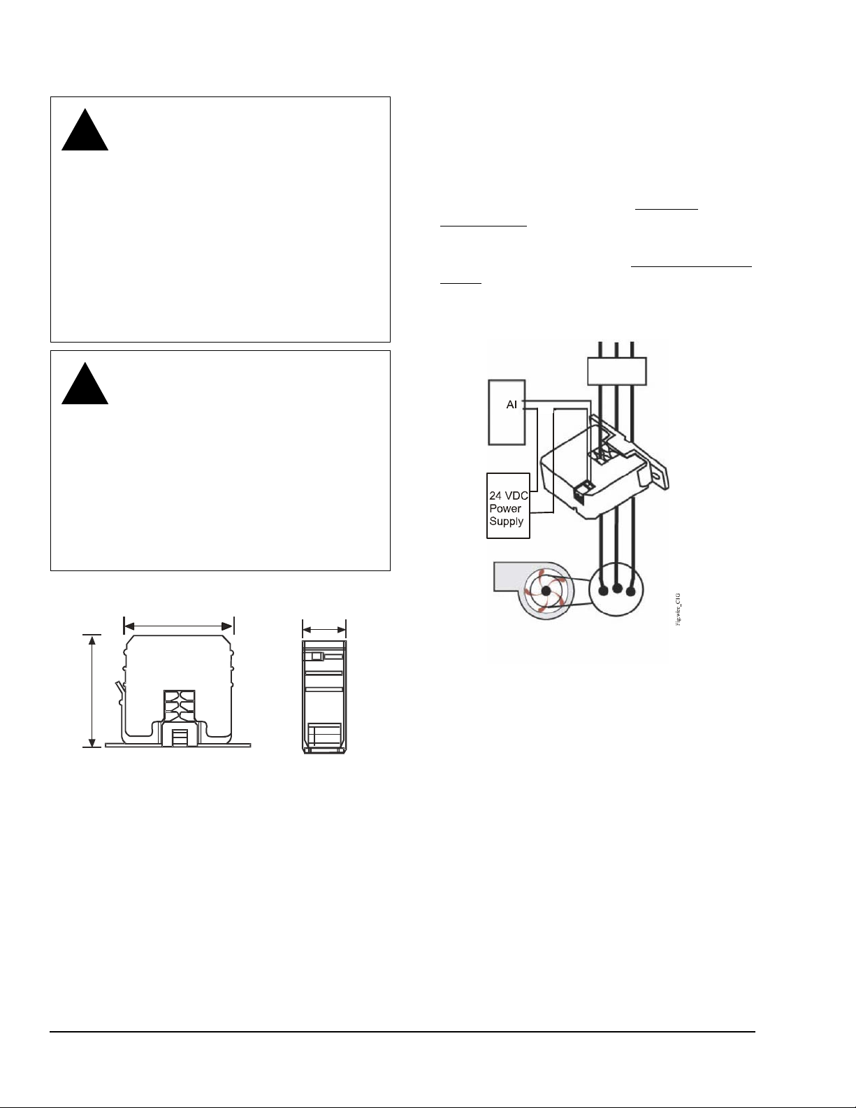
Installation
!
!
Figure 1: CTD Dimensions, in. (mm)
1-1/16 (27)
Fig:sc_sde
2-9/16 (65)
2-23/32 (69)
Fig:splt_cre_frnt
Figure 2: Model CTD-C1G00-1
Contactor
Motor
Fan or Pump
WARNING: Risk of Electric Shock.
Disconnect the power supply before
making electrical connections. Cont act with
components carrying hazardous voltage
can cause electric shock and may result in
severe personal injury or death.
AVERTISSEMENT : Risque de
décharge électrique.
Débrancher l'alimentation avant de réaliser
tout branchement électrique. Tout contact
avec des composants conducteurs de
tensions dangereuses risque d'entraîner
une décharge électrique et de provoquer
des blessures graves, voire mortelles.
WARNING: Risk of Personal Injury.
Do not touch the relay while power is
applied to it. The relay surface is hot
during use, and may cause a serious
burn upon contact.
AVERTISSEMENT : Risque de
blessure.
Ne pas toucher le relais lorsque le relais
est sous tension. La surface du relais
devient extrêmement chaude durant son
utilisation et risque de provoquer des
brûlures graves en cas de contact.
Wiring
1. Disconnect the conductor cable from the power
source.
2. Snap the split core around the power conductor
cable, and close the core until the core snaps shut.
3. Wire the CTD output terminals to the control box
Analog Input (AI) terminal. See Technical
Specifications for wire size and screw torque.
4. Select the input current range at the front panel
slide switch. See Figure 5 and Setting the Current
Range section.
5. Reconnect the power conductor cable. For a wiring
example, see Figure 2.
Dimensions
Mounting
1. Use the two screws (included) to attach the
2. Snap the CTD device into place on the mounting
mounting bracket to the back of the electrical
enclosure.
bracket.
If the measured current is too low to be detected or it is
higher than the maximum current rating of the CTD
device, use the following methods to increase or
decrease the current.
CTD Series Current Transducer Devices Installation Instructions2
Page 3

If Measured Current Is Too Low to Be Dete cted
Figure 3: CSD Device Shown with Four Turns
F
i
g
:
s
c
_
t
r
n
s
Figure 4: CTD Device with CT Transformer
Current > 135 A
Fig:spc_w ct
Figure 5: Current Setting Switch
Amperage Range
120 60 30
Fig:CTD
4-20 mA
+ -
Wrap the conductor (wire) through the sensing hole
and around the CTD body to produce multiple turns to
increase the measured current. The measured current
is equal to the actual current multiplied by the number
of turns (Figure 3).
You must scale the controller to account for the extra
turns. If four turns pass through the transducer as
shown, the normal controller reading must be divided
by 4.
IMPORTANT: Failure to derate the current cap acity
could result in damage to the CTD device when
using multiple turns to increase the measured
current. Use the following formula to determine the
new maximum current:
The new maximum current is equal to the CDT
current rating divided by the number of turns.
Example: If the new maximum current is equal to the
CDT current rating of 120 A, then
Maximum Current = 120 A / 4 = 30 A.
2. Run the CT secondary wire through the sensing
hole.
3. Terminate the two secondary wires of the 5 A CT to
each other, and then install the 5 A CT on the
monitored conductor.
4. Set the CTD device for the lowest current range
(20 or 30 A).
Setup and Adjustments
Setting the Current Range
Position the current range slide switch to a level
consistent with the load.
Table 1: Current Settings
Model Current Settings (A)
CTD-C1G00-1 30, 60, or 120
CTD-C2G00-1 30, 60, or 120
CTD-C3H00-1 20, 100, or 150
To Monitor Currents Exceeding the Maximum Current Rating of the CTD Device
For currents greater than 120 A (CTD-C1G00-1 and
CTD-C200-1), or greater than 150 A (CTD-C3H00-1),
proceed as follows.
1. Use a 5 A Current Transformer (CT) to reduce the
current passing through the CTD device, as shown
in Figure 4.
CTD Series Current Transducer Devices Installation Instructions 3
Page 4

Wiring and Output
Figure 6: CTD-C1G00-1
Amperage Range
120 60 30
Fig:CTD1
4-20 mA
+ -
-
+
+
-
AI
DDC Controller
24 VDC
Power
Supply
Figure 7: CTD-2G00-1
Amperage Range
120 60 30
Fig:CTD2
0-5 VDC
+ -
+
AI
DDC Controller
Figure 8: CTD-C3H00-1
Amperage Range
120 60 30
Fig:CTD3
0-10 VDC
+ -
+
AI
DDC Controller
Figure 9: Transducer Linear Outputs
Analog Output
Input Current
CTD-C2G00-1
5 VDC
0 VDC
0 A 30/60/
120 A
Analog Output
Input Current
CTD-C3H00-1
10 VDC
0 VDC
0 A
20/100/
150 A
A
nalog O
utp
u
t
Input Current
CTD-C1G00-1
20 mA
4 mA
0 A 30/60/
120 A
Linear Outputs
Accessories
See Table 2 for acce sso ries .
Table 2: Accessories
Code Number Description
CR-01200-0 12 VAC/VDC Single-Pole,
Single-Throw (SPST), Normally
Open (N.O.) Relay
CR-02400-0 24 VAC/VDC SPST, N.O. Relay
Repair Information
If the CTD Device fails to operate within its
specifications, replace the unit. For a replacement CTD
device, contact the nearest Johnson Controls®
representative.
CTD Series Current Transducer Devices Installation Instructions4
Page 5

Troubleshooting
Table 3: Troubleshooting
Symptom Action
The CTD device output does
not function.
There is no
CTD output
at controller.
CTD-C1G00-1 1. Verify that the loop power between the CTD terminals and the control panel analog
CTD-C2G00-1,
CTD-C3H00-1
Verify you did not exceed the maximum current range. Voltages or currents above the
rated levels may damage the CTD device.
input is 18–30 VDC.
2. Verify that the current is 4 mA without a load.
a. Turn off the monitored load.
b. Disconnect the inputs to the controller.
c. Measure the current in the power supply and CTD output loop with a multimeter.
3. Check the current loop polarity.
4. Check the clamp surface is free of dirt or debris.
5. Check the clamp is fully close d .
1. Check the current rating in monitored conductor.
2. Check the polarity of th e sensor output and controller output.
3. Check the clamp surface is free of dirt or debris.
4. Check the clamp is fully close d .
5. Measure the voltage across the CTD output terminals.
Technical Specifications
CTD-C1G00-1, CTD-C2G00-1, and CTD-C3H00-1 Current Transducer Models
Product Code CTD-C1G00-1 CTD-C2G00-1 CTD-C3H00-1
Current Range (Selectable) 30/60/120 A 30/60/120 A 20/100/150 A
Continuous Operating Current 30/60/120 A 30/60/120 A 20/100/150 A
Output 4 to 20 mA 0 to 5 VDC 0 to 10 VDC
Accuracy ±2.0% Full Scale from 10% to 100% of Selected Range
Response Time 2 Seconds to 100% of Selected Range
Sensor Supply Voltage 24 VDC (18 to 30 VDC) Self-Powered Self-Powered
Wire Size 12 to 22 AWG (2.1 to 0.6 mm) Diameter Recommended
Isolation Voltage 600 VAC rms
Temperature Range 5 to 140°F (-15 to 60°C)
Frequency Range 50/60 Hz
Humidity Range 0 to 95% RH, Noncondensing
Screw Torque 4 lb·in (0.5 N·m)
Dimensions 2-23/32 x 2-9/16 x 1-1/16 in. (69 x 65 x 27 mm)
Aperture (Sensing Hole) Size 23/32 in. x 13/16 in. (18 x 20 mm Diameter)
Compliance United States UL Listed, File E310692, CCN NRNT, Under UL 508, Industrial Control Equipment
Canada UL Listed, File E310692, CCN NRNT7, Under CAN/CSA C22.2 No. 14-05
Industrial Control Equipment
Europe CE Mark – Johnson Controls, Inc., declares that this product is in compliance with the
essential requirements and other relevant provisions of the EMC Directive and the Low
Voltage Directive.
Shipping Weight 0.35 lb (0.16 kg)
The performance specifications are nominal and conform to acceptable industry standards. For application of conditions beyond these
specifications, consult the local Johnson Controls office. Johnson Controls, Inc. shall not be liable for damages resulting from misapplication or
misuse of its products.
CTD Series Current Transducer Devices Installation Instructions 5
Page 6

Metasys® and Johnson Controls® are registered trademarks of Johnson Controls, Inc.
All other marks herein are the marks of their respective owners. © 2016 Johnson Controls, Inc.
Building Efficiency
507 E. Michigan Street, Milwaukee, WI 53202
European Single Point of Contact: NA/SA Single Point of Contact: APAC Single Point of Contact:
JOHNSON CONTROLS
WESTENDHOF 3
45143 ESSEN
GERMANY
JOHNSON CONTROLS
507 E MICHIGAN ST
MIL WAUKEE WI 53202
USA
JOHNSON CONTROLS
C/O CONTROLS PRODUCT MANAGEMENT
NO. 22 BLOCK D NEW DISTRICT
WUXI JIANGSU PROVINCE 214142
CHINA
CTD Series Current Transducer Devices Installation Instructions6
Published in U.S.A. www.johnsoncontrols.com
 Loading...