

Page 1
CSD Series Current Devices
Code No. LIT-1900454
Issued April 5, 2013
Description
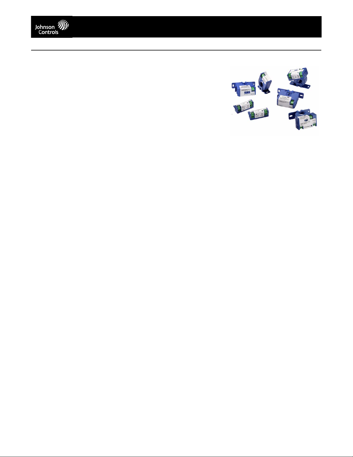
The Current Switch Device (CSD) Series of
digital output current switches are
non-intrusive devices designed to detect
current flowing through a cable or wire. A
cost-effective solution for monitoring on and
off status or proof of operation, these units are
ideal for monitoring very small current loads
on motors driving fans and blowers, pumps,
heating coils, and lighting.
The CSD models with command relays not
only monitor the current flowing through the
cable but also facilitate the start and stopping
of the motor.
These units also provide a universal
solid-state output and do not require a power
supply. Completely self-powered, these units
draw their power from current induced from
the cable or line being monitored.
CSD Series Current Devices are available in
the following types:
• solid core, setpoint fixed
• solid core, setpoint adjustable
• solid core with command relay,
setpoint adjustable
• split core, setpoint fixed
• split core, setpoint adjustable
• split core with command relay,
setpoint fixed
• split core with command relay,
setpoint adjustable
• 12 VAC/VDC and 24 VAC/VDC accessory
command relays
Refer to the CSD Series Current Devices
Product Bulletin (LIT-12011292) for important
product application information.
Features
• dual function — monitors current and motor
start and stop
• 100% solid-state output — has no moving
parts to fail
• polarity insensitive output — provides
easier wiring
• snap-in mounting bracket — simplifies
installation
• small size — fits in tight enclosures
Fixed Setpoint Models
CSD-SF0C0-1 (solid core)
• Setpoint fixed at 0.25 A
• Current range — 0.25 to 200 A
CSD-CF0A0-1 (split core)
• Setpoint fixed at 0.15 A
• Current range — 0.15 to 200 A
CSD-CF0J0-1 (split core)
• Setpoint fixed at 1.5 A
• Current range — 1.5 to 200 A
CSD-CF0J1-1 (split core with 24 V command
relay)
• Relay Single Pole, Single Throw (SPST),
Normally Open (N.O.), 10 A at 260 VAC,
5 A at 30 VDC
• Actuation coil — 20–30 VAC/DC,
40–85 mA maximum
• Setpoint fixed at 1.5 A
• Current range — 1.5 to 200 A
Adjustable Setpoint Models
CSD-SA1E0-1 (solid core)
• Multi-turn potentiometer — adjust setpoint
for application
• Adjustable setpoint — wide range from
1.0 to 135 A
• Two status Light-Emitting Diodes (LEDs)
— provide visual indication of off and on
status
CSD-SA1E1-1 (solid core with 24 V command
relay)
• Multi-turn potentiometer — adjust setpoint
for application
• Adjustable setpoint — wide range from
1.00 to 135 A
• Relay SPST, N.O., 10 A at 260 VAC,
5 A at 30 VDC
• Actuation coil — 20–30 VAC/DC,
40–85 mA maximum
• Two Status LEDs — provide visual
indication of off and on status
CSD-CA1G0-1 (split core)
• Multi-turn potentiometers — adjust setpoint
for application
• Two status LEDs — provide visual
indication of off and on status
• Adjustable setpoint — wide range from 1.25
to 135 A
CSD Series Current Device
CSD-CA1G1-1 (split core with 24 V command
relay)
• Multi-turn potentiometers — adjust setpoint
for application
• Adjustable setpoint — wide range from
1.25 to 135 A
• Relay SPST, N.O., 10 A at 260 VAC,
5 A at 30 VDC
• Actuation coil — 20–30 VAC/VDC,
40–85 mA maximum
• Two status LEDs — provide visual
indication of off and on status
CSD-SA1E2-1 (solid core with 12 V command
relay
• Multi-turn potentiometers — adjust setpoint
for application
• Adjustable setpoint — wide range from
1.00 to 135 A
• Relay SPST, N.O., 10 A at 260 VAC,
5 A at 30 VDC
• Actuation coil — 10–14 VAC/VDC,
25–45 mA maximum
• Two status LEDs — provide visual
indication of off and on status
Repair Information
If the CSD Series Current Device fails to
operate within its specifications, replace the
unit. For a replacement CSD Series Current
Device, contact the nearest
Johnson Controls® representative.
The performance specifications are nominal and conform to acceptable industry standards. For applications at conditions beyond these specifications, consult the local Johnson Controls office.
Johnson Controls, Inc. shall not be liable for damages resulting from misapplication or misuse of its products. © 2013 Johnson Controls, Inc.
www.johnsoncontrols.com
1
Page 2
CSD Series Current Devices (Continued)
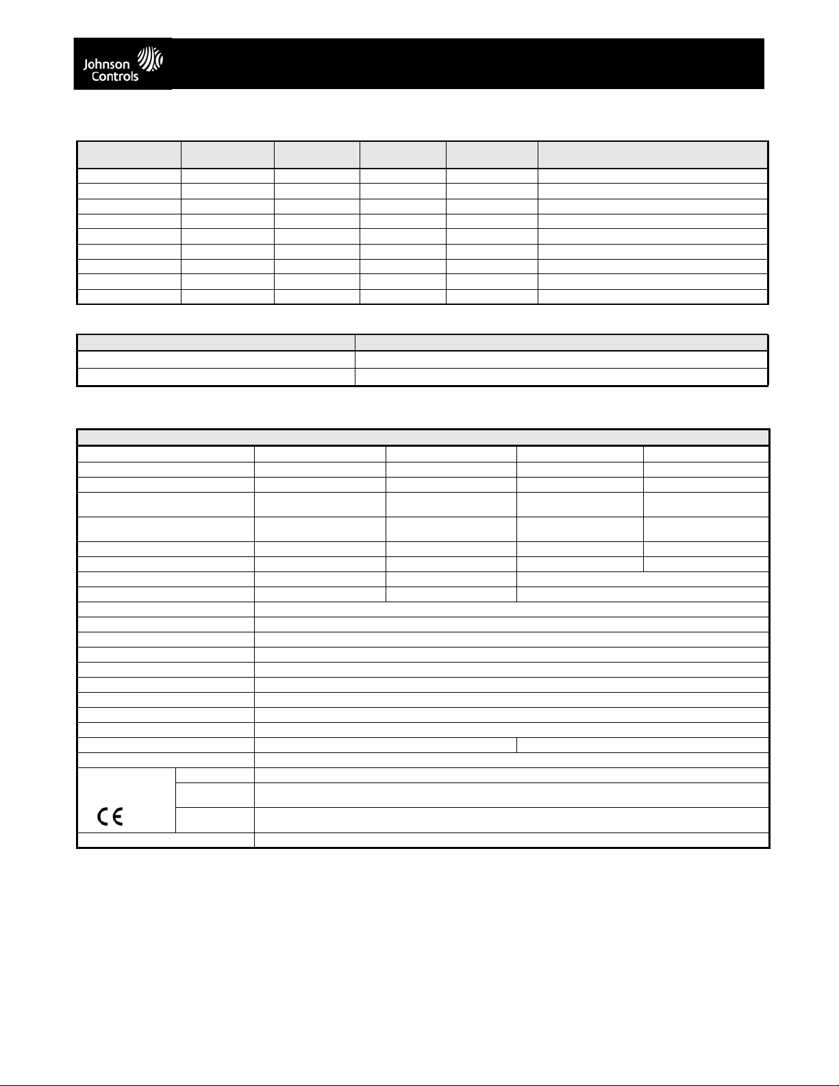
Selection Chart
Code Number Core Type Setpoint
CSD-SF0C0-1 Solid Fixed No 0.25 No
CSD-SA1E0-1 Solid Adjustable Yes 1.00 No
CSD-SA1E1-1 Solid Adjustable Yes 1.00 24 V SPST, N.O. 10 A at 260 VAC, 5 A at 30 VDC
CSD-SA1E2-1 Solid Adjustable Yes 1.00 12 V SPST, N.O. 10 A at 260 VAC, 5 A at 30 VDC
CSD-CF0A0-1 Clamp/Split Fixed No 0.15 No
CSD-CF0J0-1 Clamp/Split Fixed No 1.5 No
CSD-CA1G0-1 Clamp/Split Adjustable Yes 1.25 No
CSD-CF0J1-1 Clamp/Split Fixed No 1.5 24 V SPST, N.O. 10 A at 260 VAC, 5 A at 30 VDC
CSD-CA1G1-1 Clamp/Split Adjustable Yes 1.25 24 V SPST, N.O. 10 A at 260 VAC, 5 A at 30 VDC
Threshold
Accessories (Order Separately)
Code Number Description
CR-01200-0
CR-02400-0
1. Refer to the Command Relay Installation Instructions (Part No.24-10345-50) for more information regarding the command relays.
1
1
LED Display Low Setpoint
12 VAC/VDC SPST, N.O. Relay
24 VAC/VDC SPST, N.O. Relay
(Amperes)
Output Relay
Technical Specifications
CSD Series Current Devices - Solid Core Models
CSD-SF0C0-1 CSD-SA1E0-1 CSD-SA1E1-1 CDS-SA1E2-1
Amperage Range 0.25–200 A 1.00–135 A 1.00–135 A 1.00–135 A
Switch Setpoint Fixed Adjustable Adjustable Adjustable
Output Relay No No 24 V SPST, N.O. 10 A at
Actuation Coil No No 20–30 VAC/VDC,
Switch LED Indication No Yes Yes Yes
Relay LED Indication No No Yes Yes
Trip Setpoint Value 0.25 A 1.00 A 1.00–135 A
Current Switching Mode Under Current Sensing Over/Under Current Sensing Over/Under Current Sensing
Sensor Supply Voltage Induced from power conductor cable.
Wire Size 2.1–0.6 mm (12–22 AWG) Diameter
Status Output Switch normally open.
Switch Load Capacity 1 A at 30 VAC/42 VDC Maximum
Isolation Voltage 600 VAC rms
Temperature Range -15 to 60°C (5 to 140°F)
Frequency Range 50/60 Hz
Humidity Range 0–95% Noncondensing
Screw Torque 0.5 N·m (4 lb·in.)
Dimensions 65 x 47 x 25 mm (2-9/16 x 1-7/8 x 1 in.) 65 x 65 x 40 mm (2-9/16 x 2-9/16 x 1-19/32 in.)
Aperture (Sensing Hole) Size 18 mm Diameter (0.71 in. Diameter)
Compliance United States UL Listed, File E310692, CCN NRNT, Under UL 508, Industrial Control Equipment
Canada UL Listed, File E310692, CCN NRNT7, Under CAN/CSA C22.2 No. 14-M91
Europe CE Mark – Johnson Controls, Inc., declares that this product is in compliance with the essential requirements and other
Shipping Weight 0.16 kg (0.35 lb)
Industrial Control Equipment
relevant provisions of the EMC Directive 2004/108/EC and the Low Voltage Directive 2006/95/EC.
260 VAC, 5 A at 30 VDC
40–85 mA Maximum
12 V SPST, N.O. 10 A at
260 VAC, 5 A at 30 VDC
10–14 VAC/VDC,
25–45 mA Maximum
The performance specifications are nominal and conform to acceptable industry standards. For applications at conditions beyond these specifications, consult the local Johnson Controls office.
Johnson Controls, Inc. shall not be liable for damages resulting from misapplication or misuse of its products. © 2013 Johnson Controls, Inc.
www.johnsoncontrols.com
2
Page 3

CSD Series Current Devices (Continued)
CSD Series Current Devices - Split Core Models
CSD-CF0A0-1/
CSD-CF0J0-1
Amperage Range 0.15–200 A/
Switch Setpoint Fixed Adjustable Fixed Adjustable
Output Relay No No 24 V SPST, N.O. 10 A at
Actuation Coil No No 20–30 VAC/VDC,
Switch LED Indication No Yes No Yes
Relay LED Indication No No Yes Yes
Trip Setpoint Value 0.15 A/1.5 A 1.25–135 A 1.5 A 1.25–135 A
Current Switching Mode Under Current Sensing Over/Under Current Sensing Under Current Sensing Over/Under Current
Sensor Supply Voltage Induced from power conductor cable.
Wire Size 2.1–0.6 mm (12–22 AWG) Diameter Recommended
Status Output Switch normally open.
Switch Load Capacity 1 A at 30 VAC/42 VDC Maximum
Isolation Voltage 600 VAC rms
Temperature Range -15 to 60°C (5 to 140°F)
Frequency Range 50/60 Hz
Humidity Range 0–95% Noncondensing
Screw Torque 0.5 N·m (4 lb·in.)
Dimension 69 x 65 x 27 mm (2-23/32 x 2-9/16 x 1-1/16 in.) 69 x 65 x 44 mm (2-23/32 x 2-9/16 x 1-3/4 in.)
Aperture (Sensing Hole) Size 18 x 20 mm Diameter (0.72 x 0.78 in. Diameter)
Compliance United States UL Listed, File E310692, CCN NRNT, Under UL 508, Industrial Control Equipment
Canada UL Listed, File E310692, CCN NRNT7, Under CAN/CSA C22.2 No. 14-M91
Europe CE Mark – Johnson Controls, Inc., declares that this product is in compliance with the essential requirements and other
Shipping Weight 0.16 kg (0.35 lb)
1.5–200 A
Industrial Control Equipment
relevant provisions of the EMC Directive 2004/108/EC and the Low Voltage Directive 2006/95/EC.
CSD-CA1G0-1 CSD-CF0J1-1 CSD-CA1G1-1
1.25–135 A 1.5–200 A 1.25–135 A
260 VAC, 5 A at 30 VDC
40–85 mA Maximum
24 V SPST, N.O. 10 A at
260 VAC, 5 A at 30 VDC
20–30 VAC/VDC,
40–85 mA Maximum
Sensing
The performance specifications are nominal and conform to acceptable industry standards. For applications at conditions beyond these specifications, consult the local Johnson Controls office.
Johnson Controls, Inc. shall not be liable for damages resulting from misapplication or misuse of its products. © 2013 Johnson Controls, Inc.
www.johnsoncontrols.com
3
 Loading...