

Page 1
USER’S INFORMATION MANUAL
LISTED
OUTDOOR SPLIT-SYSTEM
AIR CONDITIONING OR HEAT PUMP
MODELS: SINGLE PHASE & THREE PHASE
TABLE OF CONTENTS
SAFETY . . . . . . . . . . . . . . . . . . . . . . . . . . . . . . . . . . . . . . . . . . . . . . . . 1
HOW YOUR SYSTEM WORKS . . . . . . . . . . . . . . . . . . . . . . . . . . . . . 1
THERMOSTATS . . . . . . . . . . . . . . . . . . . . . . . . . . . . . . . . . . . . . . . . .1
PROGRAMMABLE ELECTRONIC THERMOSTATS . . . . . . . . . . . . .2
START-UP . . . . . . . . . . . . . . . . . . . . . . . . . . . . . . . . . . . . . . . . . . . . . .2
SYSTEM OPERATION . . . . . . . . . . . . . . . . . . . . . . . . . . . . . . . . . . . . .2
LIMITED WARRANTY . . . . . . . . . . . . . . . . . . . . . . . . . . . . . . . . . . . . .4
CONT ACT INFORMATION
• Go to website at www.york.com, then click on “Contact Us” and
follow the instructions.
• Contact us by mail:
The manufacturer recommends that the user read this
manual and keep the manual for future reference.
SAFETY
This product must be installed and serviced by a qualified installer
or service agency. Improper installation, adjustment, alteration, service or maintenance can cause injury or property damage.
HOW YOUR SYSTEM WORKS
COOLING CYCLE
If your hand is wet and you blow on it, it feels cool because some of the
moisture is evaporating and becoming a vapor. This process requires
heat. The heat is being taken from your hand, so your hand feels cool.
That’s what happens with an air conditioner. During the cooling cycle,
your system will remove heat and humidity from your home and will
transfer this heat to the outdoor air.
HEATING CYCLE (HEAT PUMPS)
During the heating cycle, your system will remove heat and humidity
from the outdoor air and will transfer this heat to your home. This is possible because even 0°F outdoor air contains a great deal of heat.
Remember that your heat pump doesn’t generate much heat, it merely
transfers it from one place to another.
System Operation
Your thermostat puts full control of the comfort level in your home at
your fingertips. DO NOT switch your thermostat rapidly ON and OFF or
between HEAT to COOL. This could damage your equipment. Always
allow at least 5 minutes between changes.
SETTING THE THERMOSTAT
The main power to the system must be kept ON at all times to prevent damage to the outdoor unit compressor. If necessary, the thermostat control switch should be used to turn the system OFF.
Should the main power be disconnected or interrupted for 8 hours
or longer, DO NOT attempt to start the system for 8 hours after the
power has been restored to the outdoor unit. If heat is needed during this 8 hour period, use emergency heat.
Johnson Controls Unitary Products
Consumer Relations
5005 York Drive
Norman, OK 73069
THERMOSTATS
YOUR KEY TO COMFORT
Although thermostats may vary widely in appearance, they are all
designed to perform the same basic function: to control the operation of
your air conditioning or heat pump system. Regardless of size or shape,
each thermostat will feature a temperature indicator; a dial, arm, or
push button for selection of the desired temperature; a fan switch to
choose the indoor fan operation; and a comfort switch for you to select
the system mode of operation.
Only approved thermostats have been tested and are fully compatible
with this equipment. Please be aware that many different thermostats
operate on batteries or “power stealing” principals. These types of thermostats can not be supported as trouble free when used with this product.
If your system has been designed to allow both cooling and heating
operation, you may have either a manual change-over type, or a programmable electronic type thermostat.
Manual change-over simply means that the comfort switch must be
manually positioned every time you wish to switch from the cooling to
heating or heating to cooling modes of operation.
A complete operating instruction is provided by the manufacturer for
each thermostat. Familiarize yourself with its proper operation to obtain
the maximum comfort with minimum energy consumption.
The computerized electronic thermostat is actually a sophisticated electronic version of a manual change-over type. This thermostat includes
features which allow “set-back” temperature variations for periods of
sleep, or while you are away during the day, and means energy savings
for you. The thermostat also features a digital clock.
COOLING ONLY
If your air conditioning system is designed to provide cooling only (AC),
with no capability for heating operation (heat pump), a two-stage cooling only thermostat, with a manual, one-position “Cool” and “Off” comfort switch is all that is required for system operation.
COOLING AND HEATING (HEAT PUMP)
If your system has been designed to allow both cooling and heating
operation, you may have either a manual change-over type, or a programmable electronic type thermostat with 2-stages of cooling and 2stages of heat.
MANUAL CHANGE-OVER
Manual change-over simply means that the comfort switch must be
manually positioned every time you wish to switch from the cooling to
heating or heating to cooling modes of operation.
Johnson Controls Unitary Products 562157-UUM-F-1211
Page 2
562157-UUM-F-1211
NOTICE
PROGRAMMABLE ELECTRONIC
THERMOSTATS
The computerized electronic thermostat is actually a sophisticated electronic version of a manual change-over type. This thermostat includes
features which allow “set-back” temperature variations for periods of
sleep, or while you are away during the day, and means energy savings
for you. The thermostat also features a digital clock.
FAN OPERATION SELECTION
A multi-position fan switch allows you to choose the type of fan operation of the indoor fan.
AUTO
With the thermostat fan switch set to “AUTO”, the fan will run intermittently as required for either heating or cooling. This position will provide
the lowest operating cost. If you purchased one of our thermostats, they
have an Intelligent fan mode which continually circulates the air during
occupied modes or when you are at home, and can cycle the fan during
unoccupied mode or during the night while you sleep to further conserve energy.
ON
CONTINUOUS FAN OPERATION: With the thermostat fan switch set to
“ON”, the indoor fan will not shut off. However, the cooling (AC) or heating (heat pump) systems will still operate as required by room temperatures. This provides continuous air filtering and more even temperature
distribution to all conditioned spaces.
FAN ONLY OPERATION: On moderate days, usually during spring and
fall, when neither heating nor cooling is required, you may want to run
only the fan to ventilate, circulate and filter the air in your home or building. Set the comfort control switch to “OFF” and the fan switch to “ON”.
Be sure to return the switches to their original positions for normal operation.
START-UP
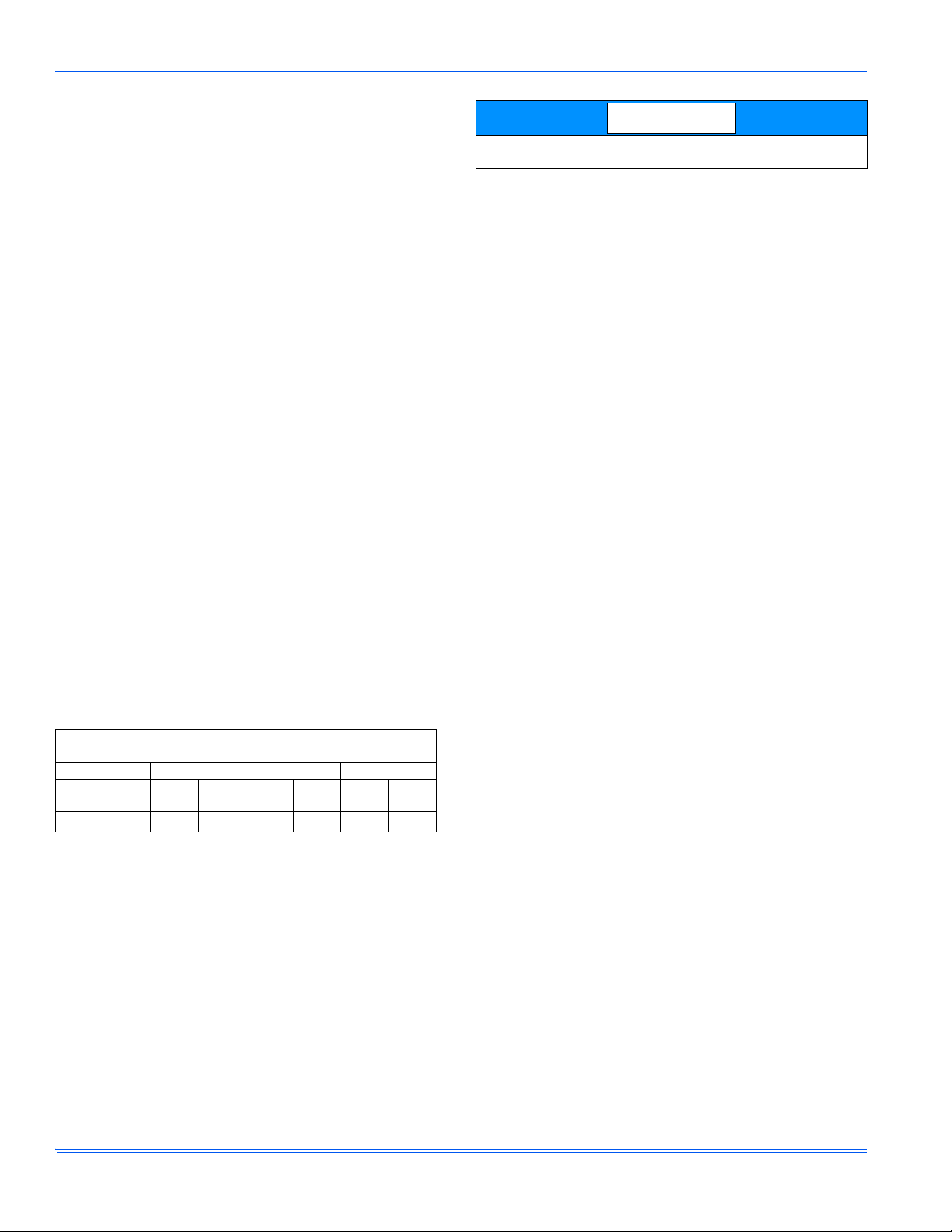
The maximum and minimum conditions for operation must be observed
to assure a system that will give maximum performance with minimum
service.
TABLE 1:
The comfort control switch is assumed to be in the “OFF” position. If the
main power supply to the outdoor and indoor units is off, turn the appropriate disconnects to the “ON” position. Place the system into operation
as follows:
1. Set temperature adjustment to the desired temperature on your
COOLING - The higher the setting, the lower the amount of energy consumed. Federal Guidelines recommend a setting of 78 °F.
HEATING - The lower the setting, the lower the amount of energy consumed. Federal guidelines recommend a setting of 65 °F or lower.
Application Limitations
Air Temperature at
Outdoor Coil, °F
Min. Max. Min. Max.
DB
CoolDBHeatDBCoolDBHeat
60 -10 115 75 57
1.
Operation below this temperature is permissible for a short period of
time, during morning warm-up.
thermostat.
Air Temperature at
Indoor Coil, °F
WB
Cool
DB
Heat
50
1
WB
Cool
DB
Heat
72 80
If your cooling and heating temperature adjustments are separate,
be sure to set both.
2. After considering “Fan Operation Selection” above, select and set
the fan operation mode you desire.
3. Move the comfort control switch to the desired mode of operation
(Cooling or Heating) found on your particular thermostat.
POWER FAILURE
When accidents, wind storms, etc. disrupt electrical power supply to
your house, switch thermostat to “OFF” position.
SYSTEM OPERATION
MANUAL CHANGE-OVER THERMOSTAT
COOLING YOUR HOME: With the comfort control switch in the
“COOL” position, the system will operate as follows: When the indoor
temperature rises above the level indicated by the temperature adjustment setting, the system will start. The outdoor unit will operate and the
indoor fan will circulate the cooled, filtered air. When the room temperature is lowered to the setting selected, the system will shut off.
HEATING YOUR HOME: If your system includes a heating unit and the
comfort control switch is in the “HEAT” position, the system will operate
as follows: When the indoor temperature drops below the level indicated by the temperature adjustment setting, the system will start. The
heating system will operate and the indoor fan will circulate the filtered
air. When the room temperature rises to the setting selected, the system will shut off. Whether heating or cooling, the fan will continue to
operate if the fan switch was set in the “ON or Intelligent” position. The
“AUTO” setting on the fan switch will allow the fan to shut off when your
system does.
ELECTRONIC THERMOSTAT
The computerized electronic thermostat, when programmed, will function automatically to operate the system as follows: When the indoor
temperature rises above the higher (COOL) setting, the outdoor unit will
operate and the indoor fan will circulate the cooled, filtered air. When
the room temperature is lowered to the selected level, the system will
shut off. The indoor fan will either shut off or run continuously, depending upon your choice of fan switch setting. When the indoor temperature drops below the lower (HEAT) setting, the heating system will
operate, and the indoor fan will circulate the heated, filtered air. When
the indoor temperature rises to the selected setting, the system will shut
off. The indoor fan will either shut off or run continuously, depending
upon your choice of fan switch setting.
TO MAXIMIZE OPERATING EFFICIENCY
HEATING CONSERVATION
For the most efficient operation, keep storm windows and doors closed
all year long. They not only help insulate against heat and cold, but they
also keep out dirt, pollen, and noise.
Closing drapes at night, keeping fireplace dampers closed when not in
use, and running exhaust fans only when necessary will help you to
retain the air you have already paid to heat.
Keep lamps, televisions, or other heat producing sources away from the
thermostat. The thermostat will sense this extra heat and will not be
able to maintain the inside temperature to the desired comfort level.
2 Johnson Controls Unitary Products
Page 3

562157-UUM-F-1211
COOLING CONSERVATION
To comfortably cool your home, your air conditioner must remove both
heat and humidity. Don’t turn your system off even though you will be
away all day. On a hot day, your system may have to operate between 8
to 12 hours to reduce the temperature in your home to a normal comfort
level.
Keep windows closed after sundown. While the outdoor temperature at
night may be lower than indoors, the air is generally loaded with moisture which is soaked up by furniture, carpets, and fabrics. This moisture
must be removed when you restart your system.
The hotter the outside temperature, the greater the load on your system. Therefore do not be alarmed when your system continues to run
after the sun has set on a hot day. Heat is stored in your outside walls
during the day and will continue to flow into your home for several hours
after sunset.
Use your kitchen exhaust fan when cooking. One surface burner on
“HIGH” requires one ton of cooling. Turn on your bathroom exhaust fan
while showering to remove humidity. However, exhaust fans should not
be run excessively. It would decrease efficiency by removing conditioned air.
You can also help your system in the summer by closing drapes or
blinds and by lowering awnings on windows that get direct sunlight.
CARE OF SYSTEM
It is strongly recommended that regular periodic preventative maintenance be performed on this equipment. The person most familiar with
the equipment in your H.V.A.C. system is a dealer. The dealer can
ensure your maintenance program meets the conditions of the Warranty”, maximize the efficiency of the equipment, and service your unit
within the federally mandated guidelines with regard to unlawful discharge of refrigerants into the atmosphere.
COIL CARE
Keep the outdoor unit free of foliage, grass clippings, leaves, paper, and
any other material which could restrict the proper air flow in and out of
the unit. The coil may be vacuumed to remove any debris from between
the fins. If the coil becomes excessively dirty, turn the main disconnect
switch to “Off” and wash the coil with your garden hose. Avoid getting
water into the fan motor and control box. Flush dirt from base pan after
cleaning the coil.
SERVICE CALLS
There are a few instances where the user can avoid unnecessary service calls. If unit stops functioning properly check the following items
before calling your servicing dealer:
1. Indoor section for dirty filter.
2. Outdoor section for leaf or debris blockage. Eliminate problem, turn
off the thermostat for 10 seconds and attempt start. Wait 5 minutes.
If system does not start, call your servicing dealer.
Your system contains environmentally friendly refrigerant R-410A,
which operates at high pressures. You may be in danger if you try
to make an attempt to repair your unit. Please contact your local
dealer.
FILTER CARE
Inspect the air filter(s) at least once a month. If they are dirty, wash
reusable filters with a mild detergent per manufacturer’s recommendations. Replace disposable filters with new filters. Install the clean filters
with “air flow” arrow in the same direction as the air flow in yo ur duct.
Filters should be clean to assure maximum efficiency and adequate air
circulation.
CLEARANCES
The minimum clearances shown below must be maintained should any
patio or yard improvements be done around the outdoor unit.
• 10" Clearance Coil Area
• 60" Overhead Clearance
• 18" to 24” is the minimum service panel access depending on
model. Refer to the installation manual for details.
• 24" Unit to Unit Distance
PARTS INFORMATION
Replacement parts are available from local contractor/dealer.
EXTENDED WARRANTY
Special warranty packages (called York CarePerformance Promise) are
available through your contractor. These packages reduce the potential
cost of service calls following the first year of operation on your cooling
(or heating/cooling) system.
SOME EFFICIENCY DO’S & DON’TS
DON’T heat or cool unused household area. Reduce supply and return
air flow to a minimum in areas which are not living spaces (storage
rooms, garages, basements, etc).
DON’T be a “thermostat jiggler”. Moving your thermostat setting will not
make your system heat or cool any faster. Adjust your thermostat to a
comfortable setting and leave it there.
DON’T restrict air circulation. Placing furniture, rugs, etc. in such a way
that they interfere with air vents will make your system work harder to
achieve a comfortable temperature level. This requires more energy,
which means greater cost to you.
DON’T locate lamps or other heat-producing appliances (radios, TV’s,
heaters, etc.) near your thermostat. The heat from these items will give
your thermostat “false information” about the temperature in the room.
DO select a comfortable thermostat setting, but keep in mind that moderation in temperature selection will save energy.
DO turn on your kitchen exhaust fan when cooking and your bathroom
exhaust fan when showering. Also, make sure your clothes dryer is
properly vented. If these items are neglected, an excess heat and
humidity condition may be created, causing your air conditioning system to run longer.
DO set your thermostat a few degrees lower than normal several hours
before entertaining a large group of people in a relatively small area.
People give off a considerable amount of heat and moisture in a closed
area.
DO keep drapes and venetian blinds closed when practical. These
items provide insulation against heat loss/gain.
DO contact a qualified service person to make repairs or adjustments to
your system. He has been trained to perform this service.
Johnson Controls Unitary Products 3
Page 4
Limited Warranty
Johnson Controls Unitary Products (her einafter “Company”) warran ts this product to be free from defects in factor y workmanship and ma terial under normal
use and service and will, at its option, repair or replace any parts, without charge, subject to the exclusions below, that prove to have such defects according to
the terms outlined on this warranty. This warranty covers only the equipment described by the Product Model Number and Serial Number on the equipment or
listed on the Warranty Registration Card and applies only to products installed in the United States or Canada.
FOR WARRANTY SERVICE OR REPAIR:
Contact the installer or a Company dealer. You may find the installer’s name on thi s page or on the equipment. You can also find a Company dealer online at
www.yorkupg.com. For help finding a servicin g dealer, contact: Johnson Controls Unitary Products, Consumer Relat ions, 5005 York Drive, Norman, OK
73069. Or, by phone 877-874-7378. All warranty serv ice or repair will be performed during regular business hours, Monday through Friday 9:00am-5:00pm.
Product Model Number: _________________________________
Unit Serial Number: ____________________________________
FOR PRODUCT REGISTRATION: For your benefit and protection, return the Warranty Registration Card to Company promptly after installation. This will initiate the warranty period an d all ow us to con tact y ou, shou ld it be come ne ces sa ry. This warranty extends onl y t o th e ori gi nal consumer purchaser and is nontransferable. For this warr anty to appl y, the product must be installed acc ording to Co mpany recomme ndati ons and s peci ficat ion s, and in ac cord ance wit h all
local, state, and national codes; and the product must not be removed from its place of original installation. The warranty period for repair or replacement parts
provided hereunder shall not extend bey ond the wa rranty pe riod state d below. In the absence of a reco rded Warranty Regist ratio n Card, the warranty period
will begin upon product shipment from Company. If you are unaware of the date the warranty became effective, contact Company at 877-874-7378 or v isit
www.upgproductregistration.com. You can register your product online at www.upgproductregistration .com or by r eturning the Warran ty Registra tion Card on
the back page of this packet.
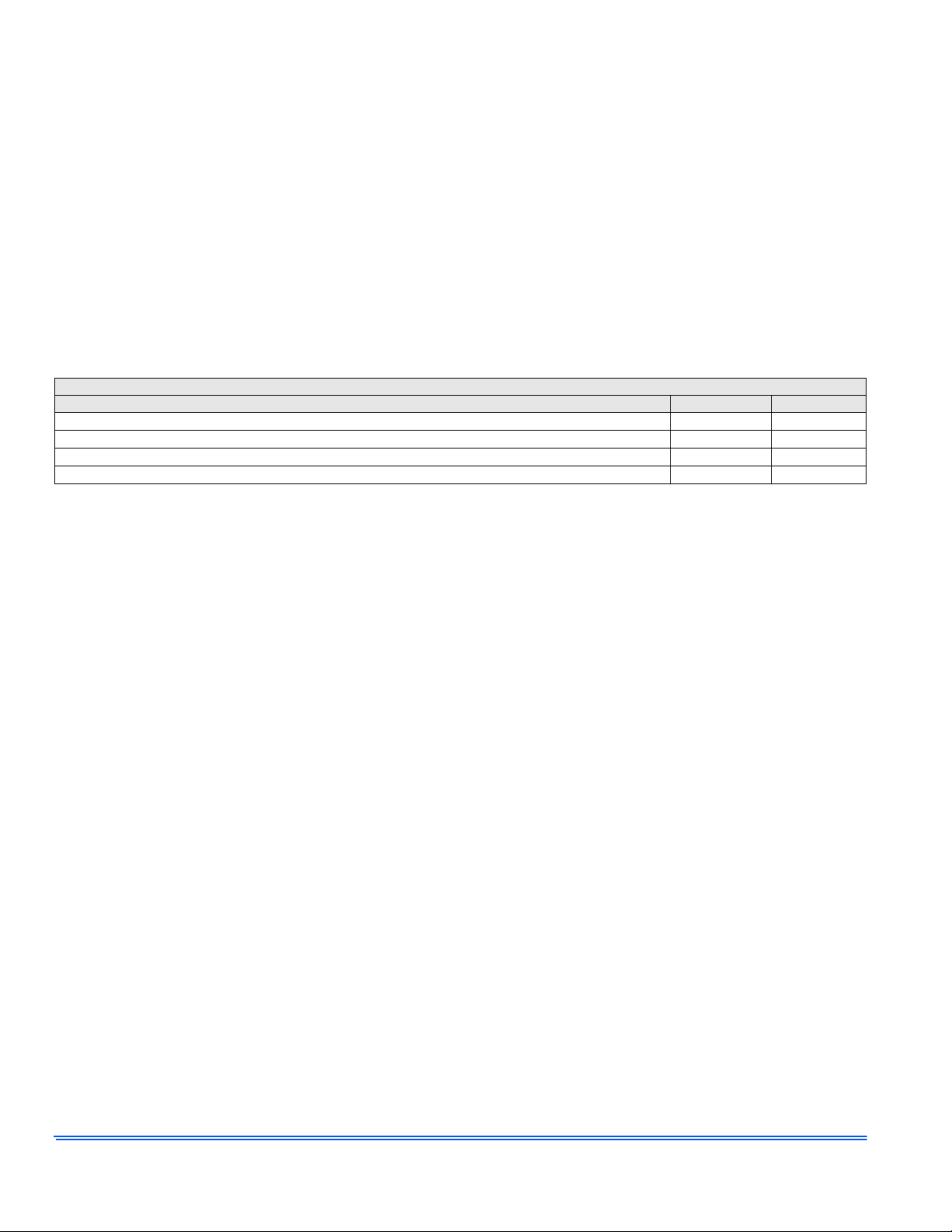
The warranty period in years, depending on the part and the claimant, is as shown in the chart below.
CONDENSING UNITS
CONDENSING UNITS COMPRESSOR PARTS
R-410A Models: GCGD, GHGD R-22 Models: GCGD, GHGD 55
R-410A Models: T(C,H)GD, T(C,H)JD*, Y(C,H)JD*, (Y,T)HJR, T(C,H)GF, T(C,H)JF, Y(C,H)JF
R-410A Models: (C,Y)ZF (C,Y)ZH, AC(6,8)B, AL(6,8)B, HC(6,8)B, HL(6,8)B, TCHD* 10 5 or 10
R-410A Models: (C,Y)ZF (C,Y)ZH, AC(6,8)B, HC(6,8)B, HL(6,8)B Premium System Warranty
* All 3 phase condensing units have 5-year compressor and 1-year parts (Model Numbers with 43/44 voltage codes).
†
To qualify for the extended 10-year parts warranty, the unit must be registered online at www.upgproductregistration.com within 90 days of installation for replacement or
90 days of closing for new home construction. In some states, registration is not required, but proof of installation may is r equir ed to qua lify for the 10- ye ar p arts warranty.
Guardian Brand products have a 5-year compressor and 5-year parts warranty and are not eligible for the 10-year parts warranty.
1. Premium System Warranty requires the following:
• Proof of a qualified factory matched system is required before Premium System Warranty becomes valid. Includes a Johnson Controls premium furnace and coil or
air handler.
• Unit registration must occur within 90 days of installation date on upgnet.com or upgproductregistration.com
• The Premium System warranty is non-transferrable and is limited to the original owner.
Company strongly recommends regular periodic preventative maintenance on this equipment. The person most familiar with the equipment in your HVAC system is a
Company dealer. The Comp any dealer can en sure your ma intenance progr am meet s the conditi ons of the "Compan y Warranty", maximize the efficiency of the equipment,
and service your unit within the mandated guidelines with regard to unlawful discharge of refrigerants into the atmosphere.
EXCLUSIONS
This warranty does not cover any:
1. Shipping, labor, or material charges or damages resulting from transportation, installation, or servicing.
2. Damages resulting from accident, abuse, fire, flood, alteration, or acts of God (tampering, altering, defacing or removing the product serial number will serve to void this warranty).
3. Damages resulting from use of the product in a corrosive atmosphere.
4. Damages resulting from inadequacy or interruption of electrical service or fuel supply, improper voltage conditions, blown fuses, or other like
damages.
5. Cleaning or replacement of filters or damages resulting from operation with inadequate supply of air or water.
6. Damages resulting from failure to properly and regularly clean air and/or water side of condenser and evaporator.
7. Damages resulting from: (I) freezing of condenser water or condensate; (II) inadequate or interrupted water supply; (III) use of corrosive wa ter;
(IV) fouling or restriction of the water circuit by foreign material or like causes.
8. Damages resulting from use of components or accessories not approved by Company (vent dampers, etc.).
9. Increase in fuel or electric cost.
This warranty is in lieu of all other warr anties, e xpres sed o r implied, including the implied warranti es of mer ch an tability and fit nes s f or a particula r
purpose.
Some states do not allow the disclaimer of implied warr anty, so that the above disclaimer may not apply to you. Some states only allow a partial
limitation on implied warranties to limit the duration of implied warranties to the duration of the express warranty. In such states, the duration of
implied warranties is hereby expressl y limite d to the durati on of the expres s warranty on the face he reof. So me states do not allow limitations on
how long an implied warranty lasts, so the above limitation may not apply to you.
In no event, whether as a result of breach of warranty or contract, tort (including negligence), strict liability, or otherwise, shall Company be liable
for special, incidental, or consequential damages, including but not limited to loss of use of the equipment or associated equipment, los t revenues
or profits, cost of substitute equipment or cost of fuel or electricity. The above limitations shall inure to the benefit of Com pany’s suppliers and
subcontractors. The above limitation on consequential damages shall not apply to injuries to persons in the case of consumer goods.
Company does not assume, or authorize any oth er person t o assume for Company, any other liability for the sale of th is product . Some states do
not allow the exclusion or limitation of incidental or consequently damages, so the above limitation may not apply to you.
This warranty gives you specific legal rights. You may also have other rights which vary from state to state.
Installation Date: _________________________________
Installing Dealer: _________________________________
5 5 or 10
1
Lifetime 10
†
†
Subject to change without notice. Published in U.S.A. 562157-UUM-F-1211
Copyright © 2011 by Johnson Controls, Inc. All rights reserved. Supersedes: 562157-UUM-E-1211
Johnson Controls Unitar y Products
5005 York Drive
Norman, OK 73069
 Loading...