

Page 1
FORM 100.50-EG12 (918)
SERIES 100
SINGLE PACKAGE ROOFTOP UNITS
ENGINEERING GUIDE
70–105 Tons
Cooling and Heating (Gas, Electric, Water, and Steam)
R-410A
Mod G
LD16707
Page 2
FORM100.50-EG12 (918)
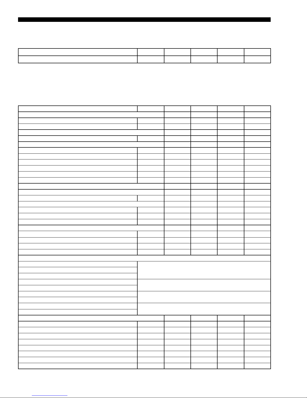
Nomenclature
BASE MODEL NUMBER YPAL070–105
1 2 3 4 5 6 7 8 9 10 11 12 13 14 15 16 17
Base Product Type Nominal (Ton)
Capacity
L : Scroll
A : Air-Cooled
P : Packaged Rooftop
Y : Johnson Controls
7
0
7
0
8
0
9
0
0
1
Application Refrigerant Voltage Supply
7 : 200 / 3 / 60
0
5
0
0
5
V : VAV, SZVAV
F : FlexSys
C : Cooling Only
N : Natural Gas Heat
G : Natural Gas Heat SS HX
M : Modulating Gas Heat
E : Electric Heat
S : Steam Heat
H : Hot Water Heat
E : R-410A
™
1
2
4
4
5
4
8 : 230 / 3 / 60
6 : 460 / 3 / 60
5 : 400 / 3 / 50
8 : 575 / 3 / 60
0 : 380 / 3 / 60
Openings
B : Bottom Supply
L : Left Supply
R : Right Supply
Return
Openings
B : Bottom Return
R : Rear Return
S : Side Return
Design Special Gas Heat
Capacity
G
A : Std. Product, Simplicity Elite
B : Special Product, Simplicity Elite
X : Std. Product, IPU
S : Special Product, IPU
N : No Gas Heat
L : Low (375 MBH)
M : Med (750 MBH)
H : High (1125 MBH)
Approvals
2
ASHRAE
90.1
COMPLIANT
JOHNSON CONTROLS
Page 3

FORM 100.50-EG12 (918)
Table of Contents
NOMENCLATURE ................................................................................................................................................... 2
INTRODUCTION ...................................................................................................................................................... 5
FEATURES AND BENEFITS ................................................................................................................................... 6
APPLICATION DATA ............................................................................................................................................. 13
PHYSICAL DATA ................................................................................................................................................... 19
WEIGHT DATA ....................................................................................................................................................... 22
COOLING PERFORMANCE DATA – 70 TON MODEL ......................................................................................... 25
COOLING PERFORMANCE DATA – 75 TON MODEL ......................................................................................... 30
COOLING PERFORMANCE DATA – 80 TON MODEL ......................................................................................... 35
COOLING PERFORMANCE DATA – 90 TON MODEL ......................................................................................... 40
COOLING PERFORMANCE DATA – 105 TON MODEL ....................................................................................... 45
HEATING PERFORMANCE DATA – GAS/ELECTRIC HEAT ............................................................................... 50
SUPPLY FAN DATA ............................................................................................................................................... 51
COMPONENT STATIC PRESSURE DROPS ........................................................................................................ 53
GAS HEAT PRESSURE DROPS ........................................................................................................................... 54
ELECTRIC HEAT PRESSURE DROPS ................................................................................................................ 55
EXHAUST FAN DATA ............................................................................................................................................ 56
RETURN FAN DATA .............................................................................................................................................. 57
ELECTRICAL DATA .............................................................................................................................................. 58
CONTROLS ........................................................................................................................................................... 61
POWER WIRING: YPAL070–105 .......................................................................................................................... 70
FIELD CONTROL WIRING ................................................................................................................................... 73
GENERAL ARRANGEMENT DRAWING – 70–80 TON MODELS ...................................................................... 75
GENERAL ARRANGEMENT DRAWING – 90–105 TON MODELS .................................................................... 81
GENERAL ARRANGEMENT DRAWING - CURB LAYOUT ................................................................................. 87
HOT WATER/STEAM COIL CONNECTION LOCATIONS .................................................................................... 89
POWER/CONTROL ENTRY DRAWING – 70-105 TON MODELS ........................................................................ 90
GUIDE SPECIFICATIONS ..................................................................................................................................... 91
JOHNSON CONTROLS
3
Page 4

FORM100.50-EG12 (918)
THIS PAGE INTENTIONALLY LEFT BLANK.
4
JOHNSON CONTROLS
Page 5
Introduction
FORM 100.50-EG12 (918)
The Johnson Controls Series 100 Single Packaged Units –
designed to meet the demands of the market for today and
tomorrow.
Better Economy...
Lower total cost of ownership
• Johnson Controls provides a standard product offering that meets the latest ASHRAE
90.1 energy efciency requirements.
• Fully modulating gas heat and greater steps of capacity control offer superior offdesign performance while maintaining optimum occupant comfort.
• Accurate ventilation control ensures that no more than the proper amount of ventilation air is utilized. This avoids the energy cost of conditioning excess outside air and
simultaneously monitors all other unit functions for maximized energy efciency.
• Flexible design congurations simplify the design process and allows the Series 100
to be applied to virtually any building application.
• Accessibility through double-wall access doors, spacious compartments and sup-
portive oors improves serviceability.
Better Ecology...
Indoor air quality features for the indoor environment
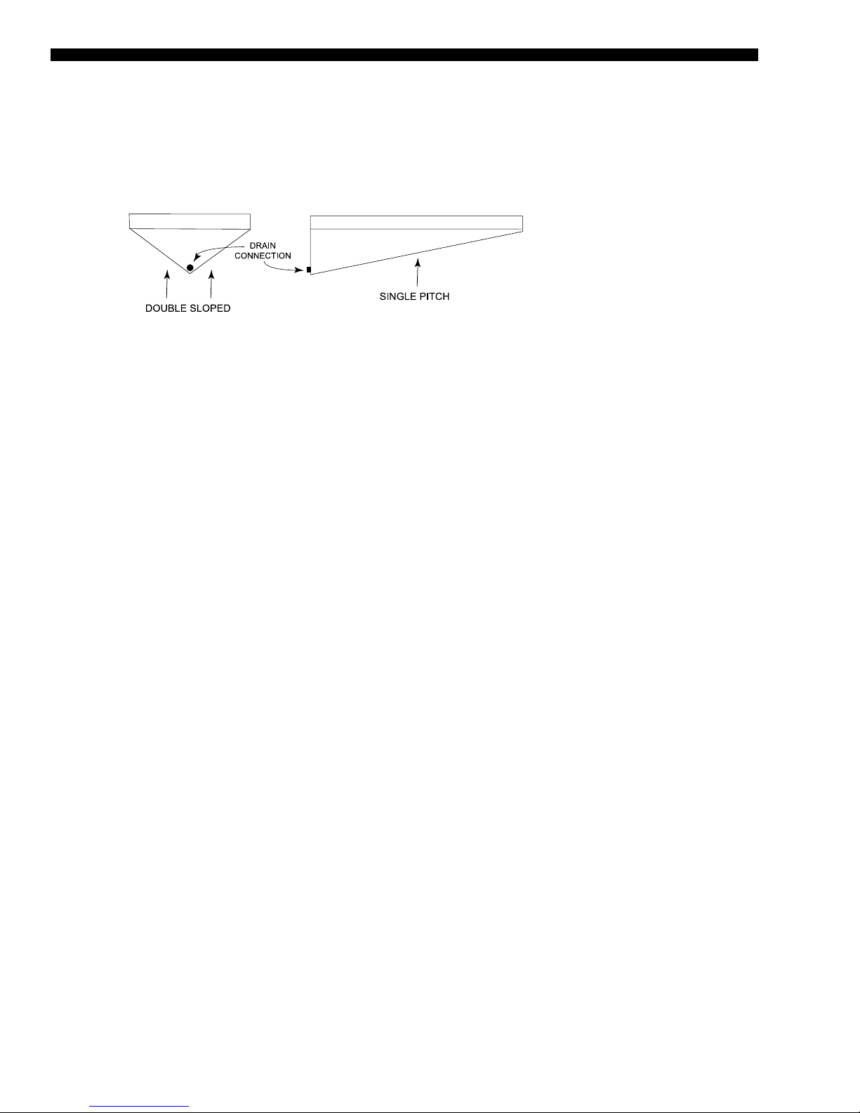
• A double-sloped stainless steel drain pan with a single drain connection ensures that all condensate is voided from the drain pan. It
is also visible and accessible for periodic inspection and cleaning re-
quired by the ASHRAE 62 IAQ standard.
• Double-wall construction of the roof, oor, doors, and walls prevents insulation bers from entering the conditioned air. The inner liner
also facilitates periodic cleaning of the unit to prevent harmful build-up
of bacteria or contaminants.
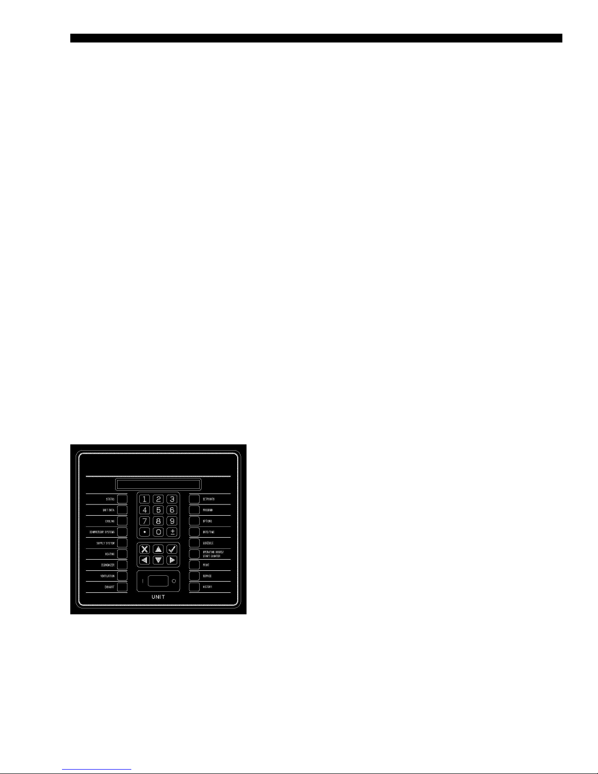
• The single package unit control center uses microprocessor logic to analyze and optimize ventilation decisions and perform demand
ventilation, airow compensation, and airow measurement to maintain the air quality at a healthy level.
LD07431
The Single Package Unit User Interface uses
microprocessor logic to optimize operation of the
Series 100 unit.
JOHNSON CONTROLS
5
Page 6

FORM100.50-EG12 (918)
Features and Benefits
AIRFLOW CONFIGURATIONS
Variable Air Volume (VAV) – Series 100 units are available for variable air volume (VAV)
applications. Control can be used with a zone sensor or building automation system. Supply fans are controlled to the supply duct static pressure setpoint, which can be reset via a
building automation system (BAS) or through a 0–5VDC analog input on the unit controller
for optimized duct static pressure control. The static pressure transducer is provided in the
single package unit, and 5/16-inch or 1/4-inch plastic tubing and static pressure sensor
must be supplied by others and installed approximately 3/4 down the longest duct run.
FlexSys™ Underfloor Air VAV – Series 100 units are configurable for underfloor air VAV
applications. Control can be used with a zone sensor or building automation system. Supply fans are controlled to the supply duct static pressure setpoint, which can be reset via
a BAS, or through a 0–5VDC analog input on the unit controller for optimized duct static
pressure control. The static pressure transducer is provided in the single package unit,
and 5/16-inch or 1/4-inch plastic tubing and static pressure sensor must be supplied by
others and installed approximately 3/4 down the longest duct run. Refer to 100.50-EG8
engineering guide for more detailed information on this application.
Single Zone Variable Air Volume (SZVAV)– Series 100 units are available for single
zone variable air volume (SZVAV) applications. Control can be used with a zone sensor
or a BAS. Supply fans are controlled based on zone temperature.
COOLING AND HEATING CONFIGURATIONS
Cooling Only – For applications where no heat is required, or heating is provided else-
where within the building HVAC system, cooling only units include an empty discharge
plenum. Supply duct connections are configurable for bottom, left or right discharge. The
supply air temperature sensor is included and factory-installed.
Staged Gas Heat – For applications requiring gas heat for morning warm-up, or other
heating needs, a staged natural gas furnace is available. The furnace is located in the
discharge plenum, downstream of the supply fan. The supply air temperature sensor is
located across the face of the supply duct opening in the unit. Furnaces are designed in
375 MBH modules with two stages in each. For 70–105 ton units, optional Propane Conversion Kits contain the necessary orifices and gas valve/parts to convert staged heat only
(not modulating) from natural gas to propane. Ignition and safety controls are included
and factory-wired. Units with staged gas heat are ETL listed.
Modulating Gas Heat – For applications requiring gas heat for morning warm-up, supply
air tempering or other heating needs, a modulating natural gas furnace is available for
finer temperature control. The furnace is located in the discharge plenum, downstream of
the supply fan. The supply air temperature sensor is located across the face of the supply duct opening in the unit. Furnaces are designed in 375 MBH modules in 8:1 turndown
increments. Three are available for the YPAL070–105 (8:1, 16:1 or 24:1 turndown). Ignition and safety controls are included and factory-wired. Units with modulating gas heat
are ETL listed.
Electric Resistance Heat – For applications where electric heat is desired, a slip-in electric resistance heat element is available in sizes from 80–250 kW depending on the single
package unit model size. The number of stages varies by size and voltage, but all have a
minimum of two stages of capacity. Units with electric heat are ETL listed.
6
JOHNSON CONTROLS
Page 7

FORM 100.50-EG12 (918)
Hot Water Heat – For applications where hot water is available for heating, a hot water
heating coil is available. A range of coil fin count selections are available to properly size the
heating for the application. Units with hot water heat are ETL listed.
Steam Heat – For applications where steam is available for heating, a steam heating coil
is available. A range of coil fin count selections are available to properly size the heating
for the application. Units with steam heat are ETL listed.
POWER OPTIONS
Single-Point Supply with Terminal Block – This configuration is standard, and includes
three terminals for the incoming 3-phase power and is the standard configuration for the
Series 100 product. It includes the enclosure, terminal-block, and interconnecting wiring
to the compressors, heater and furnace controls, all fans, etc. In this configuration, code
requires that a means of disconnect (not provided) must be installed at the site within lineof-sight of the equipment.
Single-Point Supply with Non-Fused Disconnect Switch – This option is the same as
the single-point with terminal block option except it includes a unit-mounted through-thedoor manual non-fused disconnect switch with an external, lockable handle (in compliance with Article 440-14 of N.E.C.). This option provides a means to isolate the unit power
voltage for servicing. Others must supply separate external fusing which must comply with
the National Electric Code and/or local codes.
Dual-Point Supply with Terminal Block – This option includes enclosure, terminal blocks
circuited to the supply and exhaust fans and control transformer and a second set of
terminal blocks with interconnecting wiring to the compressors, heat (if applicable) and
condenser.
Convenience Outlet – This options includes a powered 115V GFCI convenience outlet
that can be used for powering tools or lights for servicing. A protective cover plate is included while not in use. The outlet is located on the bottom left hand corner of the power
panel.
CONTROL FEATURES AND OPTIONS
Microprocessor-Based Single Package Unit Controller – All Series 100 units are
equipped with a factory-installed, programmed and commissioned unit controller with all I/O
capabilities and control sequences. The controls include all on-board diagnostic, safety and
control features to operate the single package unit. A multimedia card interface is included
for software upgrades and can be used for data logging to simplify equipment troubleshooting. Communication ports are included as standard with three alarm outputs, a shutdown
contact, remote start/stop input, smoke ventilation controls, analog inputs for supply air
temperature and duct static pressure rest, along with a variety of other capabilities.
Standard Ambient – YPAL070–105 models operate down to 45.0°F as standard.
Low Ambient on Circuits One, [One and Two], or [One, Two, and Three] – This op-
tion includes low ambient control of the first [first and second] [first, second, and third]
circuit(s) down to 0.0°F through the use of suction and discharge pressure transducers
on the circuit(s).
Pressure Transducers with Readout Capability – This option includes suction and dis-
charge pressure transducers on each circuit and provides pressure readout of all circuits
at the unit control panel.
JOHNSON CONTROLS
7
Page 8

FORM100.50-EG12 (918)
Features and Benefits (Cont'd)
Wall-Mount Zone Sensor – A 10 kOhm thermister type III NTC zone sensor for wall
mounting. This zone sensor is for sensing temperature only, and does not include any
setpoint adjustment features.
COMMUNICATIONS
BACnet® MS/TP (RS-485) Communications – This communication option is standard on
every Series 100 unit. Communications to the unit are through a twisted pair, and the wire
terminations are on the primary unit control board. See supplemental information for the
available control points and PICS/Bibbs statements of conformity.
Modbus™ RTU Communications – This communication option is standard on every Series 100 unit and can be used in lieu of the BACnet communications (only one can be
used at a time). See supplemental information for the available control points.
FILTER OPTIONS
Filter Options – Two-inch throwaway, cleanable, carbon coated MERV 8 or pleated
MERV 8 filters in an angled rack are available. For higher filtration requirements, optional
rigid filter racks are available with 12-inch 65% (MERV 11) or 95% (MERV 14) efficient
rigid filters. Two-inch MERV 8 pre-filters are included with rigid filter options. The rigid filter
rack option is available without filter media where field-supplied filters are required.
Zone Sensor
OUTSIDE AIR DAMPER OPTIONS
Manual Damper – This option includes a manually adjustable outside air damper. It is
manually adjustable at the unit by setting a mechanical stop between 0–100%.
Two-Position – This outside air damper option is controlled to a two positions, opened
and closed. Determination of the damper position is based on the occupancy schedule. In
the occupied mode, the outside air damper is positioned to the manually configured point
(set by mechanical stop). In the unoccupied mode, the damper is fully closed.
Modulating Economizer – This option includes modulating outdoor air and return air
dampers that are software interlocked (YPAL070–105 software interlock) and positioned
by fully modulating, solid state damper actuators. Control of the damper is via a standard
ambient outdoor air dry bulb sensor, or optional single or comparative enthalpy controls.
Airflow Measurement – Optional outside airflow measurement is available on units
equipped with a Modulating Economizer.
CO2 Sensors – Optional carbon dioxide sensors for occupied space that operate demand
ventilation control opening outside air dampers to ventilate building. The CO2 sensors can
operate in a single or comparative control scheme.
Rain Hoods on Outside Air Intakes – For all options with outside air intake openings,
rain hoods are provided as standard to keep moisture from entering the equipment. The
rain hoods are an integral part of the unit and are rotated into place at the jobsite.
RELIEF SYSTEM
Barometric Relief – This option does not include an exhaust or return fan, but rather
uses barometric relief dampers to exhaust air from the building. The dampers will open
relative to the building pressure. The opening pressure is adjustable via a spring tension
adjustment.
8
JOHNSON CONTROLS
Page 9

FORM 100.50-EG12 (918)
On/Off Powered Exhaust – This option provides simple building pressure control. It can
be controlled via a building pressure signal, or via outside air damper control. This option
is not available for VAV units.
Modulating Powered Exhaust with Damper Control – This option consists of a constant-speed exhaust fan with a discharge damper that is modulated to control the flow
of exhaust air. The damper control logic is based on the building static pressure setpoint
within the single package unit controller. The static pressure transducer is provided in
the return plenum of the single package unit, and 5/16-inch or 1/4-inch plastic tubing and
static pressure sensor must be supplied by others and installed in a representative location in the building.
Modulating Powered Exhaust with a VFD – This option consists of a VFD to modulate the
speed of the exhaust fan to control the flow of exhaust air. The VFD control logic is based
on the building static pressure setpoint within the single package unit controller. The static
pressure transducer is provided in the return plenum of the single package unit, and 5/16inch or 1/4-inch plastic tubing and static pressure sensor must be supplied by others and
installed in a representative location in the building.
Powered Return Fan with Exhaust – This option uses single width, single inlet (SWSI)
plenum fan(s) to control building pressure. The fan motors are driven by a VFD to maintain
a constant return plenum pressure. An exhaust hood with a modulating control damper
is used to maintain building pressure via the building static pressure. The static pressure
transducer is provided in the return plenum of the single package unit, and 5/16-inch or
1/4-inch plastic tubing and static pressure sensor must be supplied by others and installed
in a representative location in the building. The powered return fan is also available without the exhaust capabilities. For units with no exhaust capabilities, the HVAC system must
provide alternate means of controlling building pressure.
SUPPLY FAN OPTIONS
Double Width, Double Inlet (DWDI) Forward-Curved Supply Fan – The standard sup-
ply air blower in the YPAL070–80 models is a forward-curved supply fan. This fan is good
for medium static pressures and high airflows.
DWDI Airfoil Supply Fan – The standard supply air blower in the YPAL090–105 is an
airfoil blade supply fan. This fan is also available as an option on YPAL070–080 for higher
static conditions. This fan offers higher efficiency and lower sound in certain applications.
Fan Skid Isolation – The entire supply fan assembly is isolated from the unit base with
one- (standard) or two-inch deflection springs, or one (standard) or two-inch deflection
springs with seismic restraints.
Supply and Exhaust Fan Motors – Premium efficiency ODP and premium efficiency
TEFC motors are available all meeting the Energy Policy Act of 1992 (EPACT).
Supply Fan VFD and Manual Bypass – For VAV applications, VFDs are provided to
modulate airflow. Optional manual bypass can also be provided to allow full airflow in the
event of a VFD failure.
Direct Drive Plenum (DDP) Fan – A direct drive plenum (DDP) supply fan provides outstanding reliability and efficiency, eliminating the possibility of conditioned air supply interruption due to a broken belt and the pollution of conditioned air with belt dust. The supply
fan can be optionally equipped with a piezo ring to precisely measure the amount of air
delivered to the conditioned space. The speed of the supply fan is controlled by a VFD.
JOHNSON CONTROLS
9
Page 10
FORM100.50-EG12 (918)
Features and Benefits (Cont'd)
EVAPORATOR SECTION
Double Sloped Stainless Steel Drain Pan – The Series 100’s stainless steel drain pan is
factory-mounted and installed on every unit. A condensate drain trap is needed, and must
be provided and installed in the field by others.
LD08022
NOTE
This is a visual reference only. Actual drain pan pitch will vary.
FIGURE 1 - DRAIN PAN DETAIL
Double Wall Construction – Double-wall construction is the standard construction of the
Series 100 and incorporates powder coated outer panels and corner post for maximum
exterior surface protection.
Factory Shrink-wrap – All Series 100 single package units are shipped from the factory
with factory-fresh shrink-wrap packaging. No longer does the contractor need to worry
about dirt and debris clogging up condenser coils or moisture leaking into the air handler
on the units way to the job site or rigging yard.
Copper Fins – For more extreme climates that aggressively can attack aluminum, copper tube evaporator coils with copper fins are available. (This is not recommended for
units in areas where they may be exposed to acid rain or environments where ammonia
is present)
CONDENSER FEATURES AND OPTIONS
Scroll Compressors – Reliable, efficient, trouble-free operation is the true measure of
a single package unit’s value. That’s why Johnson Controls Series 100 Single package
units use established scroll compressor technology to deliver dependable, economical
performance in a wide range of applications. With the Series 100 Single package units,
you get the latest generation of compressor enhancements added to the scroll’s inherent
strengths. The simplicity of a hermetic scroll compressor allows the use of fewer moving
parts to minimize breakdown.
Multiple Compressor Staging – Through the use of the scroll compressor, the Series
100 has the ability to stage it’s cooling by enabling and disabling multiple single stage
compressors on multiple circuits.
Compressor Circuiting – The Series 100 is designed so that only 2 scroll compressors
are in tandem within one refrigeration circuit. This means more reliable compressors,
and less equipment down time. With multiple circuits, if a compressor should ever fail on
one circuit, the other circuit/s will remain operational to maintain occupied loads. In sizes
70–105T, the Series 100 has three independent refrigeration circuits per unit.
Condenser Fan Motors – The condenser fan motors used on the Series 100 unit are
Totally Enclosed Air Over (TEAO) to provide maximum durability through any season.
10
JOHNSON CONTROLS
Page 11

FORM 100.50-EG12 (918)
Hot Gas Bypass – This options permits continuous, stable operation at capacities below
the minimum step of unloading by introducing an artificial load on the evaporator. For
models YPAL070–105, it is used on the lead circuit.
Replaceable Core Liquid Line Driers – Liquid line driers are standard on the Series 100
single package unit. An option is provided for replaceable core driers.
Post-Coated Fins – Optional coil-coating used on condenser coils for seashore and other
corrosive applications (with the exception of strong alkalis, oxidizers, wet bromide, chlorine and fluorine in concentrations greater than 100 ppm).
Compressor Sound Blankets – Optional compressor acoustic sound blankets are available for sound sensitive applications.
ROOF CURBS
Full Perimeter Roof Curbs – This option includes a knock-down 14-inch high roof curb
for use with wood nailer (by others). Roof curb supports the entire perimeter of the unit.
Partial Perimeter Roof Curbs – This option includes a knock-down 14-inch high roof
curb for use with wood nailer (by others). Roof curb supports the air handling section with
a separate support under the condenser end.
CABINET FEATURES AND OPTIONS
Double-Wall Access Doors - Full-sized access doors provide easy access into the unit
for routine maintenance and inspection. Solid wall liners encase insulation and prevent
damage and erosion into the airstream.
Diffuser Section – An optional diffuser section is available downstream of the supply
fan in the extended discharge plenum cabinet option. The diffuser section distributes the
airflow from the fan evenly across the downstream filter bank to optimize filter life and
effectiveness. The diffuser design is optimized to provide uniform flow at minimal airside
pressure loss.
Downstream Final Filter Rack – An optional 90–95% efficient MERV 14 12-inch rigid
filter rack and filters is available downstream of the supply fan and diffuser segment for
hospital applications (YPAL070–105 only). A magnahelic pressure gauge is included and
visible from the outside of the unit for servicing and code compliance.
Blank Section – An optional blank section is available downstream of the supply fan and
diffuser section.
ACCESSORIES
Filter Switch – An optional dirty filter alarm can be provided that will provide an alarm
when the filters require cleaning.
Magnahelic Filter Pressure Gauge – On units equipped with downstream filtration, a
magnahelic filter gauge is included and visible on the exterior of the unit. The filter gauge
measures the air pressure drop for through the rigid filter bank to indicate when replace-
ment is required.
JOHNSON CONTROLS
11
Page 12
FORM100.50-EG12 (918)
Features and Benefits (Cont'd)
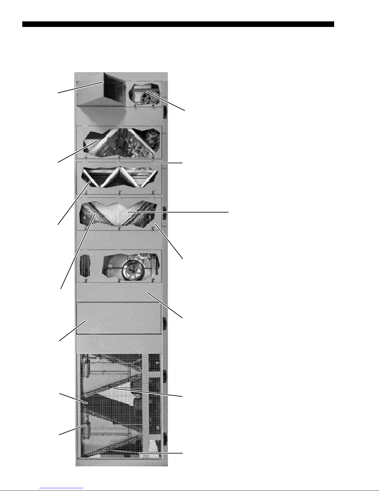
YPAL070–105 MODEL
Rainhoods to
prevent moisture
from entering the
unit
Optional airflow
measurement
station
Centrifugal fan
powered exhaust fan
or optional plenum
return fan
Doors on both
sides of unit and
tie backs for unit
servicing
00567VIP
Angled or
rigid flat filter
section
Distributor tubes
protected in plastic
sleeves
Optional
horizontal
supply air
openings
Condenser wire
screen Optional
louvers available
Angled evaporator
Double-sloped
stainless steel
IAQ drain pan
and intermediate
drain pan
Complete
double-wall
construction of
walls, floors,
ceiling, and
panels
V-banked condenser
coils to protect from
hail damage
coil for lower face
velocities
Optional
replaceable core
filter driers
12
Factory-installed
single package
unit controller
JOHNSON CONTROLS
Page 13

Application Data
GENERAL
The Series 100 Single Packaged units are designed for outdoor installation. When selecting a site for installation, be guided by the following conditions:
• Unit must be installed on a level surface.
• For the outdoor location of the unit, select a place having a minimum sun exposure
• Also avoid locations beneath windows or between structures.
• Optional condenser coil protection should be used for seashore locations or other harsh
• The unit should be installed on a roof that is structurally strong enough to support the
FORM 100.50-EG12 (918)
and an adequate supply of fresh air for the condenser.
environments.
weight of the unit with a minimum of deection. It is recommended that the unit(s) be
installed not more than 15 feet from a main support beam to provide proper structural
support and to minimize the transmission of sound and vibration. Ideally, the center
of gravity should be located over a structural support or building column.
• Location of unit(s) should also be away from building ue stacks or exhaust ventilators to prevent possible reintroduction of contaminated air through the outside air
intakes.
• Be sure the supporting structures will not obstruct the duct, gas or wiring connections.
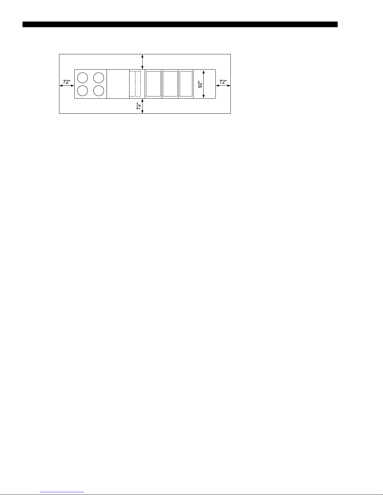
• Proper service clearance space of 6 feet around the perimeter of the unit, 8 feet on
one side for coil servicing, and 12 feet to any adjacent units is required to eliminate
cross contamination of exhaust and outdoor air, and for maintenance tasks such as
coil pull and cleaning. No obstructions should be above the condensing unit section.
LOCATION
Of the many factors that can effect the location of equipment, some of the most important
to consider are Structural, Acoustical and Service clearances. Proper attention should be
made at the design stage to ensure proper structural support. In cases where equipment
is being replaced, be aware of building design to insure support is adequate for the ap-
plication.
The next most important consideration in applying single package units equipment is that
of sound from the equipment. Special care should be made to keep the single package
unit away from sound sensitive areas such as conference rooms, auditoriums and executive offices and any other room that may have potential for tenant occupancy. Possible
locations could be above hallways, mechanical or utility rooms.
Finally, service clearances should be maintained in single package unit design to insure
safe access to the unit. Unit clearances are designed so that technicians have enough
space between units, building walls, and edges of building to gain access safely. In cases
where space is limited, please call your local Johnson Controls representative for additional information.
JOHNSON CONTROLS
13
Page 14
FORM100.50-EG12 (918)
Application Data (Cont'd)
96"
LD08044
NOTES
1. Under certain conditions these clearances may be encroached upon.
2. This is a visual reference for all Series 100 units.
RIGGING
Proper rigging and handling of the equipment is mandatory during unloading and setting
it into position to retain warranty status.
Spreader bars must be used by cranes to prevent damage to the unit casing. All lifting lugs
must be used when lifting the single package unit unit. Fork lifts will damage the single
package unit and are not recommended.
Care must be taken to keep the unit in the upright position during rigging and to prevent
damage to the watertight seams in the unit casing. Avoid unnecessary jarring or rough
handling.
UNIT PLACEMENT
• Elevated – Elevated roof curbs or dunnage steel can be used to support the unit in
order to raise it to specic heights. When this type of placement is required, be sure
to keep unit access in mind. Cat walks or other forms of unit access may be required
to one or both sides of the unit, depending on your area of the country and the local
codes that are enforced. Please check with local ofcials to ensure the application
conforms to local codes and regulations.
• Ground Level Locations – It is important that the units be installed on a substantial
base that will not settle, causing strain on the refrigerant lines and sheet metal and
resulting in possible leaks. A one-piece concrete slab with footers extended below
the frost line is highly recommended. Additionally, the slab should be isolated from
the main building foundation to prevent noise and vibration transmission to the building structure.
For ground level installations, precautions should be taken to protect the unit from
tampering by, or injury to, unauthorized persons. Erecting a fence around the unit is
common practice.
• Roof curb – Johnson Controls offers optional roof curbs designed specically for the
Series 100 footprint. These curbs come in full perimeter or open condenser models
and are shipped disassembled and require eld assembly and installation. For bottom supply and return openings, the curbs have matching connections to ease installation. A pipe chase that matches the single package unit pipe chase is also included
in the curb footprint for through-the-curb utility connections.
The curb should be located according to the location recommendations above, and
properly sealed to prevent moisture and air leakage into and out of the duct system.
Flexible collars should be used when connecting the duct work to prevent unit noise
transmission and vibration into the building.
Duct work should be supported independently of the unit.
14
JOHNSON CONTROLS
Page 15
FORM 100.50-EG12 (918)
TABLE 1 - SUPPLY AIR DUCT CONNECTION CONFIGURATIONS
UNIT CONFIGURATION
Cooling only X X X
Cool/gas heat X X
YPAL
070–105
Cool/electric heat X
Cool/hydronic heat X
Cooling only X X X
Cool/hydronic heat X X X
STANDARD CABINET
EXTENDED CABINET
SUPPLY AIR
BOTTOM LEFT RIGHT
TABLE 2 - RETURN AIR DUCT CONNECTION CONFIGURATIONS
UNIT CONFIGURATION
No exhaust X X X X
Barometric relief
YPAL
070–105
damper
Powered exhuast
fan (all types)
Powered return fan X
BOTTOM LEFT RIGHT FRONT
X X X
X X X
RETURN AIR
UNIT ORIENTATION
For applications with multiple single package units located in close proximity on the roof,
the orientation of the unit may be important to reduce the potential for re-entrainment of
outside airflow. Regardless of the outside air and exhaust air openings on a unit, all single
package unit applications can permit recirculation of exhaust air to the return, if applied
improperly.
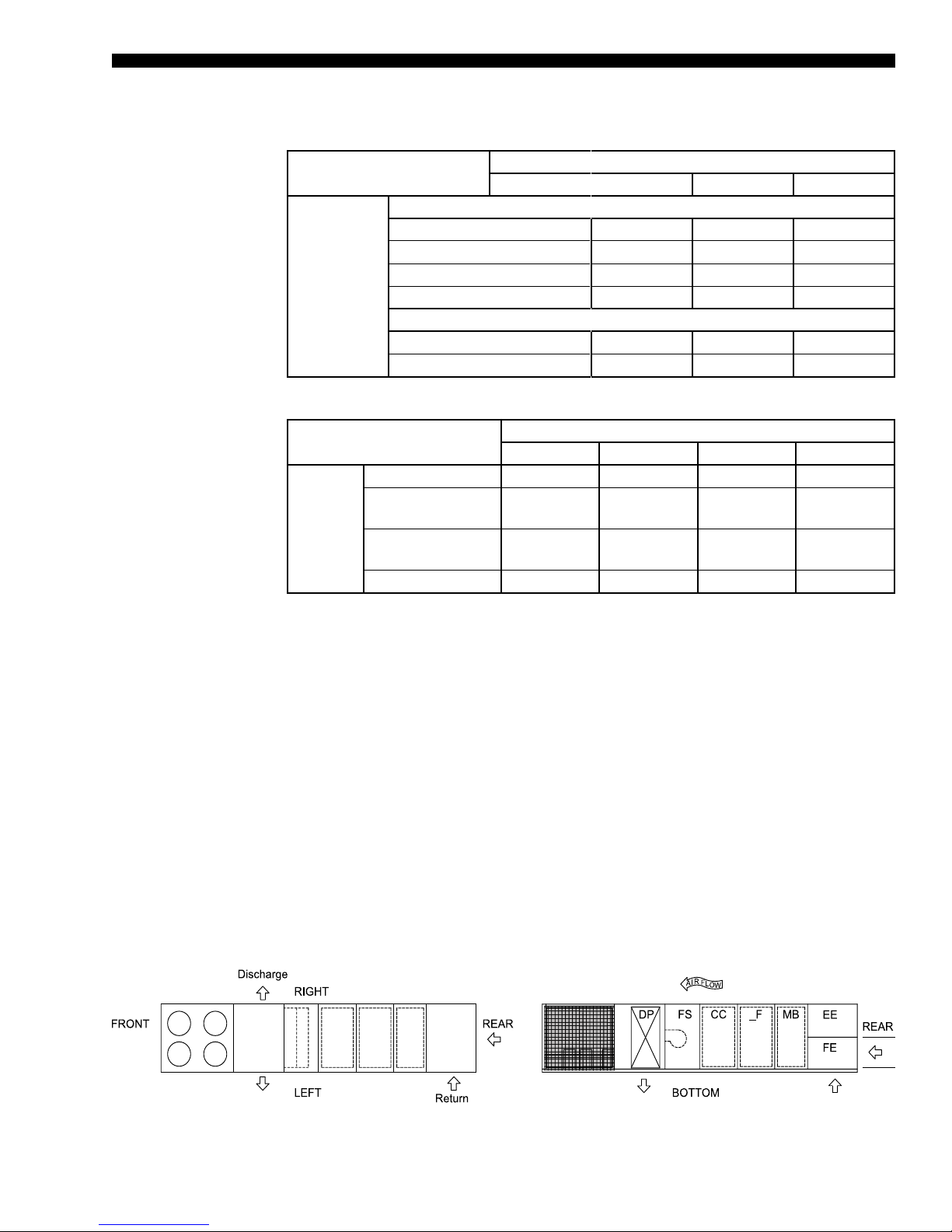
HORIZONTAL APPLICATIONS
The spectrum of applications for single package units in today’s market is continuing to
grow wider by the day. Flexibility in unit design and construction is a must in today’s mar-
ket in order to insure safe and sound applications of HVAC equipment. If the application
calls for horizontal supply and return air, Johnson Controls can ship it from the factory
as a horizontal unit. This option eliminates the need for field modification of equipment
saving time and money. The Series 100 can support a left discharge on all units and/or
right discharge on all cooling only units and hydronic heat units with an extended cabinet.
Return air can be brought through the end or side return air inlet making the unit specific
to building needs.
NOTE
This diagram is provided as a visual reference of the Series 100 discharge & return air openings & locations for all sizes. Please refer to the
dimensional data for exact size & location of panels and openings.
JOHNSON CONTROLS
LD08045
15
Page 16
FORM100.50-EG12 (918)
Application Data (Cont'd)
ECONOMIZER
The economizer section is used to maintain indoor air quality, and also to reduce energy
consumption by using outdoor air cooling in lieu of mechanical cooling. If outdoor air is
appropriate for cooling, but not sufficient for the cooling demand, mechanical cooling will
stage on as necessary until the cooling load is met.
Dual (comparative or differential) enthalpy operation is the most accurate and efficient
means of economizer operation. The IPU controller monitors the return and outside air
energy content, and selects the lower of the two for operation.
VAV SUPPLY AIR PRESSURE CONTROL
Traditional packaged single package unit systems use inlet guide vanes (IGVs) for duct
static pressure control. These control supply duct pressure by modulating dampers (introducing losses and inefficiencies) on the inlet of the fan, open and closed. Johnson
Controls variable frequency drives (VFDs) offer superior fan speed control and quieter,
energy efficient operation.
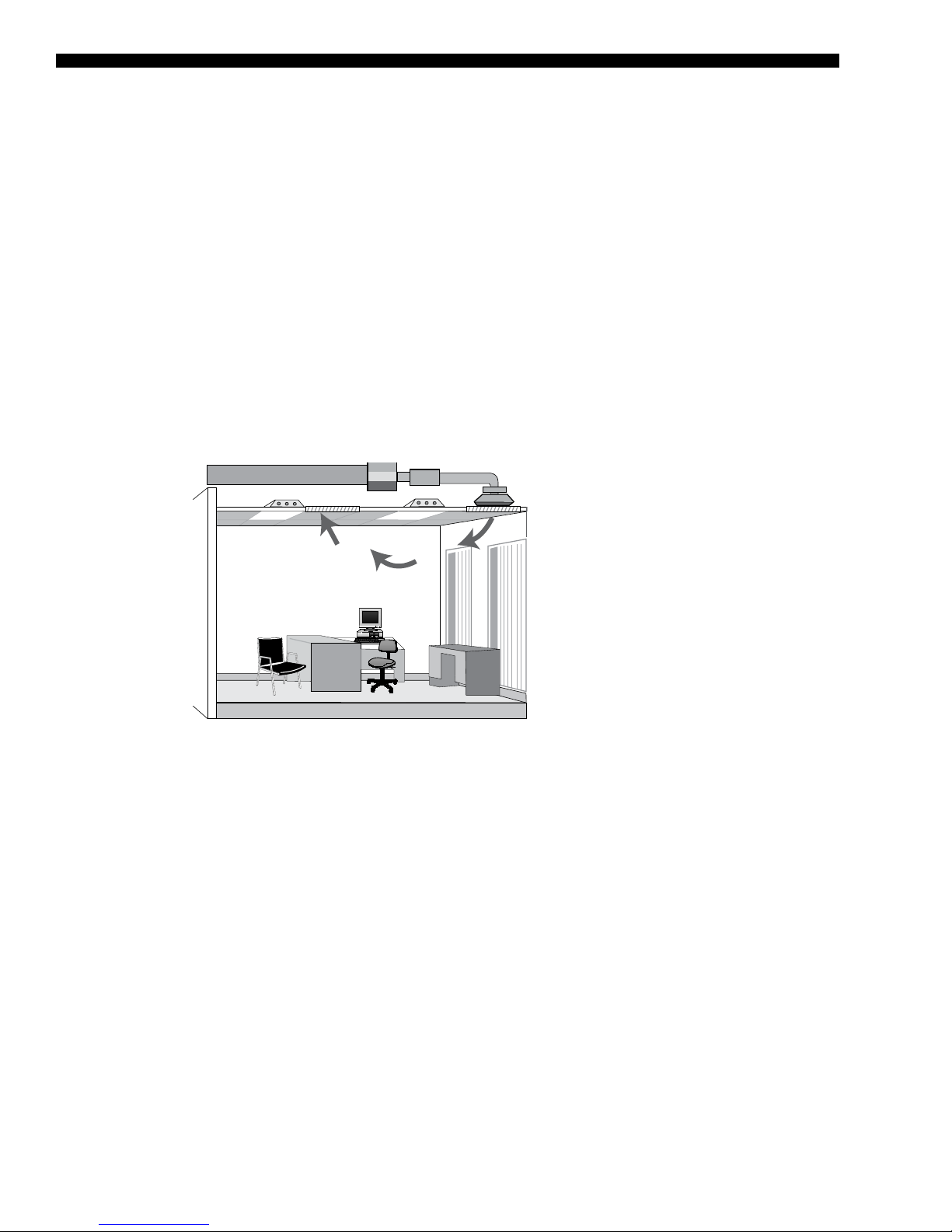
FIGURE 2 - TRADITIONAL OVERHEAD VAV AIR DELIVERY SYSTEM
For VAV applications, the Johnson Controls Series 100 unit uses a VFD to modulate fan
speed and maintain a constant duct static pressure. VFDs offer superior control over the
operation of the unit at part load, and offer the additional benefits of quieter and more efficient operation when compared to IGV.
FLEXSYS
™
The traditional approach to HVAC design in commercial buildings has been to supply
conditioned air through extensive overhead duct networks to an array of diffusers spaced
evenly in the ceiling. In Figure 1, the conditioned air is both supplied and returned at ceiling level. Ceiling plenums must be designed large enough to accommodate the supply
ducts that run through them. Return air is typically configured as ceiling plenum return
without any ductwork. This type of air distribution, known as the “well-mixed” type, is the
most common system in use. This conventional HVAC system is designed to promote
complete mixing of supply air with room air, thereby maintaining the entire volume of all air
in the space (from floor to ceiling) at the desired space setpoint temperature. In addition,
to meet IAQ requirements, an adequate supply of fresh outside air must be introduced to
this mix. A key disadvantage to this control strategy is that it has no provisions to accommodate different temperature preferences among the building occupants or to provide
preferential ventilation in the occupied zone.
16
JOHNSON CONTROLS
Page 17
FORM 100.50-EG12 (918)
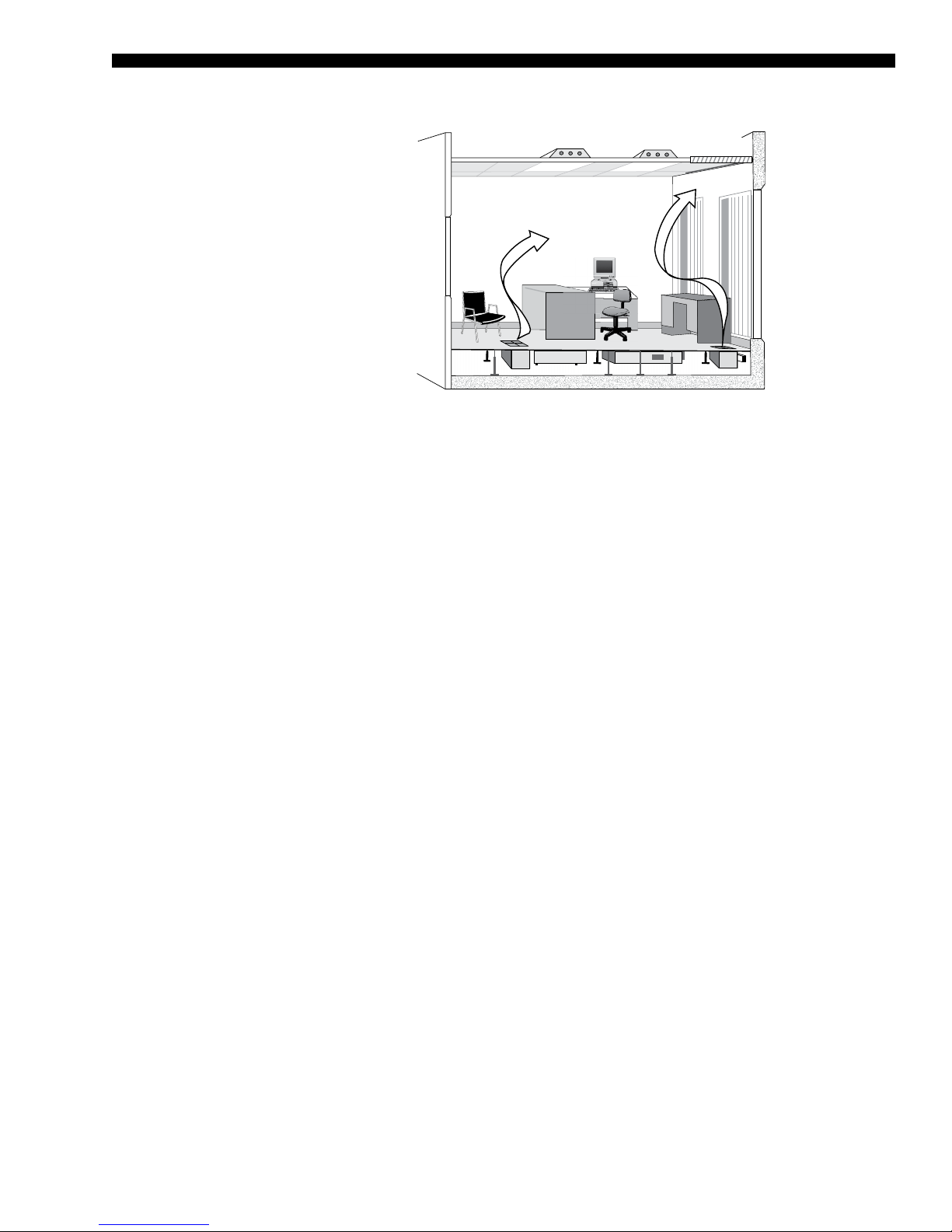
FIGURE 3 - JOHNSON CONTROLS FLEXSYS UNDERFLOOR AIR DELIVERY
SYSTEM
With the Johnson Controls FlexSys Underfloor Air System, conditioned air is ducted to the
underfloor plenum. As shown in Figure 3 on page 17, this conditioned air flows freely
throughout the plenum to individual supply discharge outlets. Unlike the larger single supply duct outlets typical of overhead systems, underfloor systems are configured to have a
large number of smaller supply outlets, in close proximity to the building occupants. These
adjustable outlets provide an opportunity for nearby occupants to have some amount of
control over thermal comfort conditions in their local environment. Air is returned from the
room at ceiling level (unducted plenum return is shown). The resulting overall floor-toceiling airflow pattern takes advantage of the natural buoyancy produced by heat sources
in the space and more efficiently removes heat loads and contaminants from the space,
particularly for cooling applications. In fact, some of the most important advantages of
underfloor systems over ceiling-based systems occur during cooling conditions, which
are required year-round in the vast majority of interior office space in many parts of the
United States.
HARSH ENVIRONMENTS – CONDENSER AND EVAPORATOR COIL PROTECTION
For harsh environmental conditions such as seashore applications, Johnson Controls offers two types of coil protection: copper fin evaporator coils and post coated condenser
coils. Johnson Controls recommends that for corrosive environments that copper fins be
used to protect the evaporator coils. In areas where chemicals that can corrode copper
are present, such as ammonia, Johnson Controls recommends that post coated condenser coild be used for maximum protection.
BUILDING PRESSURE CONTROL SYSTEMS
Building pressure control systems are often necessary when economizers are used to
bring in outdoor air. Without proper building exhaust, the building may become over pressurized. The pressure control system maintains the proper building pressure by expelling
the appropriate amount of air from the building.
Return fans – For high return static applications, such as buildings with ducted return
systems, a powered return fan may be necessary to maintain building pressure control.
Johnson Controls offers a powered return fan that is located in the return plenum. This fan
operates coincidentally with the supply fan and draws return air back through the return
ductwork and into a pressurized plenum. A control damper modulates to exhaust air out
of the building and maintain the building pressure. A second control damper modulates to
provide return air from the ductwork to the unit air mixing section.
JOHNSON CONTROLS
17
Page 18

FORM100.50-EG12 (918)
Application Data (Cont'd)
The return fan configuration is available in two forms: with and without an exhaust damper. The option with the exhaust damper provides a means of building exhaust at the unit.
In some applications, the exhaust system is located elsewhere and the unit is not required
to provide building exhaust. In these situations, the Series 100 can be offered without the
exhaust damper to help reduce installed costs.
Exhaust/relief fans – In this application, a powered exhaust fan may be suitable, however careful consideration of the fan type is necessary. Johnson Controls offers a centrifugal powered exhaust fan to perform this function. Some manufacturers use a propeller
exhaust fan, which cannot handle the static pressure requirements.
For systems with moderate to low return static pressure, an exhaust fan is recommended.
The benefit of the exhaust fan is that it does not run all of the time, and may facilitate com-
pliance with the ASHRAE 90.1 fan motor horsepower requirement.
The exhaust fan operates in parallel with the supply fan. In this arrangement, the supply
fan handles the full static pressure requirements of the system. For normal building pressure control, the exhaust fan operates to draw air from the return plenum and exhaust it
out of the building.
The exhaust fan configuration is available in two forms, modulating and non-modulating.
Modulating is the most common and recommended for the majority of applications, while
non-modulating should be used only in certain circumstances.
In the modulating exhaust system, the volume of airflow exhausted from the building is
proportional to the entering volume of outside air. Control is accomplished via either a
discharge damper or a VFD. Johnson Controls recommends the use of a VFD to reduce
energy consumption, sound levels and improved reliability due to fewer moving parts.
In the non-modulating exhaust system, the exhaust airflow is constant whenever the exhaust fan is operating. This type of control should only be used to either assist a smoke
purge system or when a system requires a constant volume of exhaust airflow.
ACOUSTICAL CONSIDERATIONS
The Series 100 unit is designed for lower sound levels than competitive units by using flexible fan connections, fan spring isolators, double-wall construction, multiple fan options,
and lower speed and horsepower fans. For VAV applications, VFDs are used instead of
inlet guide vanes. Additional sound attenuation can be obtained using compressor sound
blankets when necessary.
Even with these equipment design features, the acoustical characteristics of the entire
installation must never be overlooked. Additional steps for the acoustical characteristics
of a single package unit installation should be addressed during the design phase of a
project to avoid costly alterations after the installation of the equipment. During the design
phase of a project, the designing engineer should consider, at a minimum, the impact of
the equipment location, single package unit installation, building structure, and duct work.
18
JOHNSON CONTROLS
Page 19
FORM 100.50-EG12 (918)
Physical Data
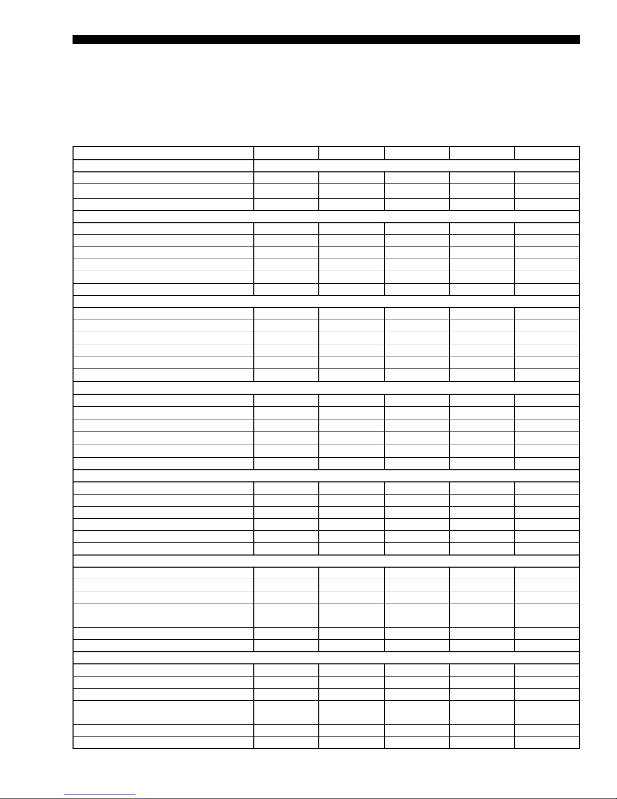
TABLE 3 - PHYSICAL DATA – MODELS 70–105
MODEL SIZE 70 75 80 90 105
COMPRESSOR DATA
Quantity/Size (Nominal HP) 6x10 4x11, 2x13 4x13, 2x11 4x15, 2x13 3x20, 3x15
Type Scroll Scroll Scroll Scroll Scroll
Capacity Steps (Qty x %) 6x16 4x16, 2x18 4x17, 2x15 4x18, 2x15 3x14, 3x19
SUPPLY FAN AND DRIVE
Quantity 1 1 1 1/1 1/1
Type FC FC FC AF AF
Size 28-25 28-25 28-25 32 32
Motor Size Range (min. to max. HP) 10–50 10–50 10–50 10–50 10–50
Airow Range (min. to max. CFM) 14,000–29,000 15,550–29,000 15,000–32,000 17,500–36,000 21,000–36,000
Static Pressure Range (min. to max. ESP) 0–4 inches 0–4 inches 0–4 inches 0–6 inches 0–6 inches
OPTIONAL AIRFOIL SUPPLY FAN
Quantity 1/1 1/1 1/1 1/1 1/1
Type AF AF AF AF AF
Size 32 32 32 32 32
Motor Size Range (min. to max. HP) 15–50 15–50 15–50 15–50 15–50
Airow Range (min. to max. CFM)
Static Pressure Range (min. to max. ESP)
OPTIONAL DIRECT DRIVE PLENUM (DDP) SUPPLY FAN
Quantity
Type
Size
Motor Size Range (min. to max. HP)
Airow Range (min. to max. CFM)
Static Pressure Range (min. to max. TSP)
EXHAUST FAN
Quantity 2 2 2 2 2
Type FC FC FC FC FC
Size 18-18 18-18 18-18 18-18 18-18
Motor Size Range (min. to max. HP 10–20 10–20 10–20 10–20 10–20
Airow Range (min. to max. CFM) 4,000–32,000 4,000–32,000 4,000–32,000 4,000–32,000 4,000–32,000
Static Pressure Range (min. to max. ESP) 0–2 inches 0–2 inches 0–2 inches 0–2 inches 0–2 inches
OPTIONAL EXHAUST FAN
Quantity 2/1 2/1 2/1 2/1 2/1
Type FC FC FC FC FC
Size 20-18 20-18 20-18 20-18 20-18
Motor Size Range (min. to max. HP, total
for two fans)
Airow Range (min. to max. CFM) 4,000–36,000 4,000–36,000 4,000–36,000 4,000–36,000 4,000–36,000
Static Pressure Range (min. to max. iwg) 0–2 inches 0–2 inches 0–2 inches 0–2 inches 0–2 inches
OPTIONAL RETURN FAN
Quantity 2/2 2/2 2/2 2/2 2/2
Type Plenum Plenum Plenum Plenum Plenum
Size 270 270 270 270 270
Motor Size Range (min. to max. HP, total
for two fans)
Airow Range (min. to max. CFM) 4,000–32,000 4,000–32,000 4,000–32,000 4,000–36,000 4,000–36,000
Static Pressure Range (min. to max. iwg) 0–3 inches 0–3 inches 0–3 inches 0–3 inches 0–3 inches
14,000–29,000 15,550–29,000 15,000–32,000 17,500–36,000 21,000–36,000
0–6 inches 0–6 inches 0–6 inches 0–6 inches 0–6 inches
1 1 1 1 1
DDP DDP DDP DDP DDP
402-9-100/120 402-9-100/120 402-9-100/120 402-9-100/120 402-9-100/120
10–75 10–75 10–75 10–75 10–75
14,000–29,000 15,550–29,000 15,000–32,000 17,500–36,000 21,000–36,000
1–8 inches 1–8 inches 1–8 inches 1–8 inches 1–8 inches
5–30 5–30 5–30 5–30 5–30
10–30 10–30 10–30 10–40 10–40
JOHNSON CONTROLS
19
Page 20
FORM100.50-EG12 (918)
Physical Data (Cont'd)
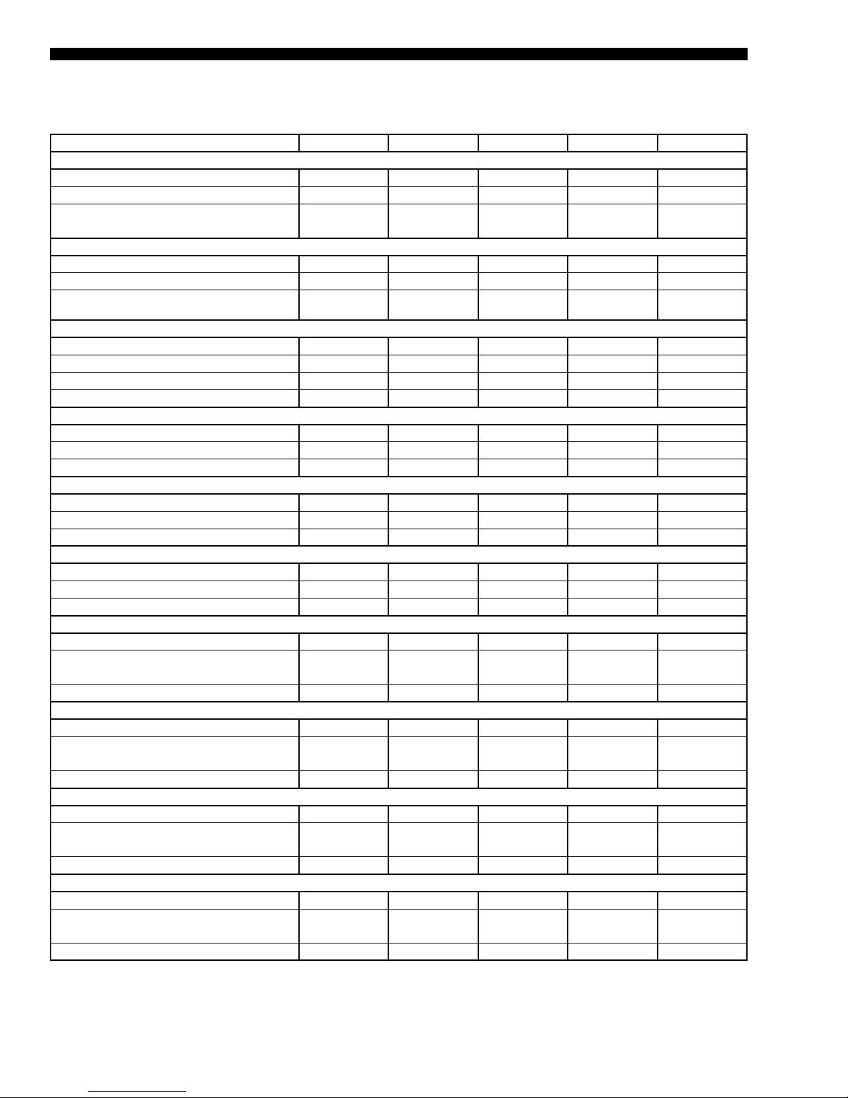
TABLE 3 - PHYSICAL DATA – MODELS 70–105 (CONT'D)
MODEL SIZE 70 75 80 90 105
EVAPORATOR COIL
Size (square feet) 56.9 56.9 56.9 56.9 56.9
Number of Rows/Fins per Inch 4/17 3/17 3/17 3/17 5/17
Tube Diameter/Surface
CONDENSER COIL (R-410A)
Size (square feet) 164 164 164 164 164
Number of Rows/Fins per Inch 1/21 1/21 1/21 1/21 1/21
Tube Diameter/Surface
CONDENSER FANS
Quantity 6 6 6 6 6
Type Prop. Prop. Prop. Prop. Prop.
Diameter (inch) 36 36 36 36 36
Power (HP each) 2 2 2 2 2
FILTERS - 2-INCH THROWAWAY (PRE-FILTER POSITION)
Quantity 10/15 10/15 10/15 12/18 12/18
Size (length x width) (inch) 25x16/25x20 25x16/25x20 25x16/25x20 25x16/25x20 25x16/25x20
Total Filter Face Area (square feet) 77.1 77.1 77.1 92.5 92.5
FILTERS - 2-INCH CLEANABLE (PRE-FILTER POSITION)
Quantity 10/15 10/15 10/15 12/18 12/18
Size (length x width) (inch) 25x16/25x20 25x16/25x20 25x16/25x20 25x16/25x20 25x16/25x20
Total Filter Face Area (square feet) 77.1 77.1 77.1 92.5 92.5
FILTERS - 2-INCH PLEATED, 30% EFFICIENT (PRE-FILTER POSITION) (MERV 8)
Quantity 10/15 10/15 10/15 12/18 12/18
Size (length x width) (inch) 25x16/25x20 25x16/25x20 25x16/25x20 25x16/25x20 25x16/25x20
Total Filter Face Area (square feet) 77.1 77.1 77.1 92.5 92.5
FILTERS - 12-INCH RIGID 65%, 2-INCH 30% PRE-FILTER (PRE-FILTER POSITION) (MERV 11)
Quantity 2/8/9 2/8/9 2/8/9 8/12 8/12
Size (length x width) (inch)
Total Filter Face Area (square feet) 55.8 55.8 55.8 61.6 61.6
FILTERS - 12-INCH RIGID 95%, 2-INCH 30% PRE-FILTER (PRE-FILTER POSITION) (MERV 14)
Quantity 2/8/9 2/8/9 2/8/9 8/12 8/12
Size (length x width) (inch)
Total Filter Face Area (square feet) 55.8 55.8 55.8 61.6 61.6
FILTERS - 2-INCH CARBON (PRE-FILTER POSITION) (MERV8)
Quantity 10/15 10/15 10/15 12/18 12/18
Size (length x width) (inch)
Total Filter Face Area (square feet) 77.1 77.1 77.1 92.5 92.5
FILTERS - 12-INCH RIGID 95% IN POST-FILTER POSITION (MERV 14)
Quantity 2/7/9 2/7/9 2/7/9 7/12 7/12
Size (length x width) (inch)
Total Filter Face Area (square feet) 55.1 55.1 55.1 61.1 61.1
3/8 inch/
enhanced
1mm micro
channel
16x20/25x16/
25x20
16x20/25x16/
25x20
16x20/25x16/
25x20
16x20/25x16/
25x20
3/8 inch/
enhanced
1mm micro
channel
16x20/25x16/
25x20
16x20/25x16/
25x20
25x16/25x20 25x16/25x20 25x16/25x20 25x16/25x20
16x20/25x16/
25x20
3/8 inch/
enhanced
1mm micro
channel
16x20/25x16/
25x20
16x20/25x16/
25x20
16x20/25x16/
25x20
3/8 inch/
enhanced
1mm micro
channel
25x16/25x20 25x16/25x20
25x16/25x20 25x16/25x20
25x16/25x20 25x16/25x20
3/8 inch/
enhanced
1mm micro
channel
20
JOHNSON CONTROLS
Page 21
FORM 100.50-EG12 (918)
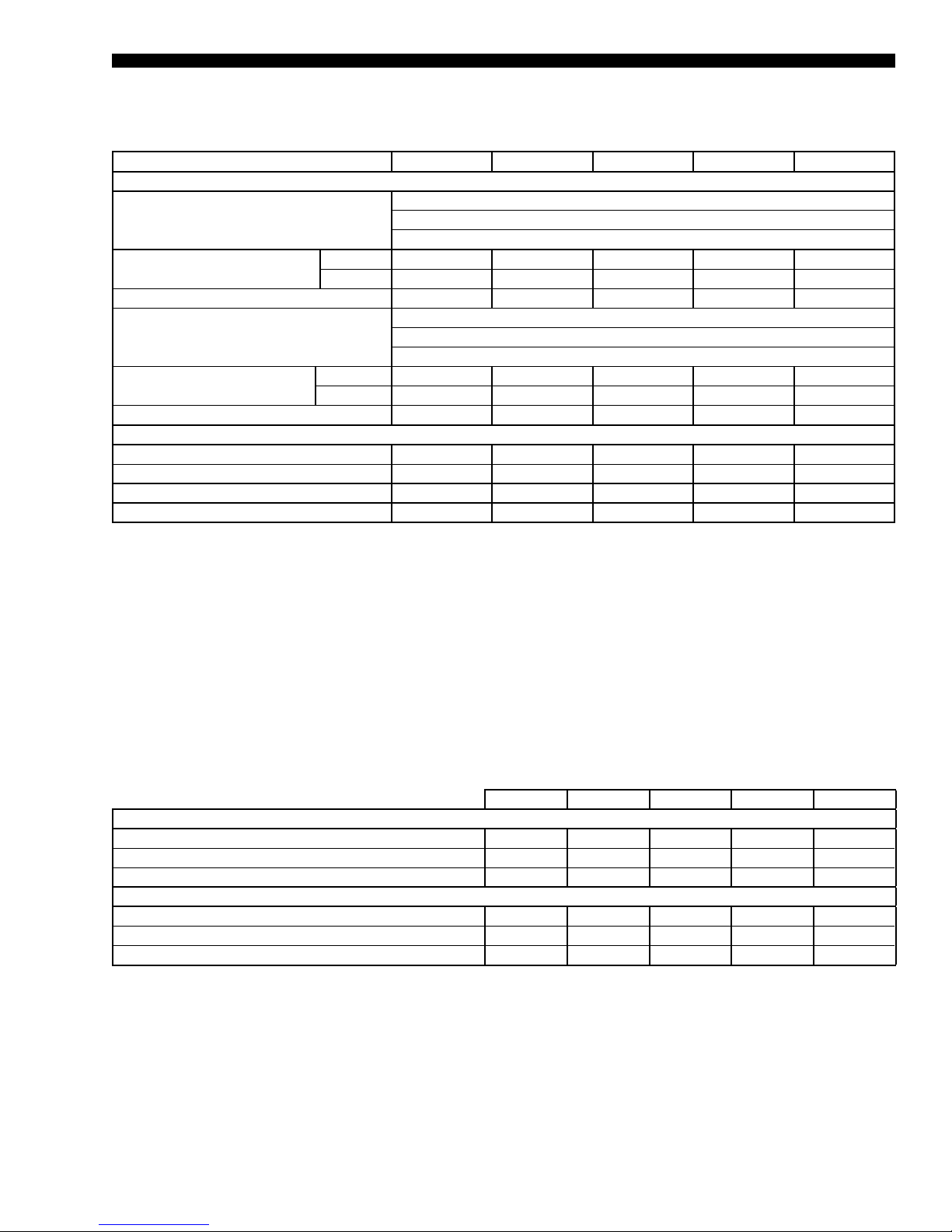
TABLE 3 - PHYSICAL DATA – MODELS 70–105 (CONT'D)
MODEL SIZE 70 75 80 90 105
GAS FURNACE
Stanged Furnace Sizes
(input/ouput/stages)
Gas Pressure Range
(min. to max. iwg)
Natural 4.5–10.5 4.5–10.5 4.5–10.5 4.5–10.5 4.5–10.5
Propane 11.0–13.0 11.0–13.0 11.0–13.0 11.0–13.0 11.0–13.0
Airow Range (min. to max. CFM) 6,950–36,000 6,950–36,000 11,150–36,000 15,150–36,000 15,150–36,000
Modulating Furnace Sizes
(input/ouput/stages)
Gas Pressure Range
(min. to max. iwg)
Natural 4.5–10.5 4.5–10.5 4.5–10.5 4.5–10.5 4.5–10.5
Propane 11.0–13.0 11.0–13.0 11.0–13.0 11.0–13.0 11.0–13.0
Airow Range (min. to max. CFM) 8,250–36,000 8,250–36,000 11,150–36,000 15,150–36,000 15,150–36,000
ELECTRIC HEATERS
Size Range (min. to max. kW) 80–200 80–200 108–250 108–250 108–250
Heating Steps
1
2-6 2-6 2-6 2-6 2-6
MINIMUM OA TEMP. FOR MECH. CIG. 45 45 45 45 45
LOW AMBIENT OPTION MIN. OA TEMP. 0 0 0 0 0
375 MBH / 300 MBH / 2 stages
750 MBH / 600 MBH / 4 stages
1125 MBH / 900 MBH / 6 stages
375 MBH / 300 MBH / 8:1 turndown
750 MBH / 600 MBH / 16:1 turndown
1125 MBH / 900 MBH / 24:1 turndown
NOTES
1. Electric heat steps and airow range depends on voltage and size. Consult Table 13 on page 50 for minimum allowable airow. Consult
Table 31 on page 60 for the number of steps for a given voltage and unit size.
Weights are for components only and need to be added to the extended cabinet weights. The diffuser is required in the extended cabinet for
any unit with hot water or nal lter option.
TABLE 4 - REFRIGERANT CHARGE DATA
70 75 80 90 105
REFRIGERANT CHARGE (R-410A STD CABINET)
SYS 1 - LB 44.3 38 38 41.5 45.4
SYS 2 - LB 38.5 32.4 35.3 32 39.6
SYS 3 - LB 42.4 33 33 36.2 45.4
REFRIGERANT CHARGE (R-410A EXTD CABINET)
SYS 1 - LB 47 40.7 40.7 44.2 48.1
SYS 2 - LB 41.2 35.1 38 34.7 42.3
SYS 3 - LB 45.4 35.7 35.7 38.9 48.1
JOHNSON CONTROLS
21
Page 22
FORM100.50-EG12 (918)
Weight Data
TABLE 5 - APPROXIMATE BASE OPERATING WEIGHTS (LBS)
MODEL SIZE 70 75 80 90 105
Approximate Unit Weight 10461 10433 10449 10799 10935
NOTES
1. Unit base weights include the following features: sheet metal, control panels, refrigerant, compressors, condenser assemblies, mini-
mum capacity supply fan, and 2-inch throwaway lter.
2. Base weights shown represent approximate operating weights and have a ±10% accuracy. To calculate weight for a specic congura-
tion, use YORKworks or contact a Johnson Controls sales representative.
TABLE 6 - COMPONENT WEIGHTS (LBS)
MODEL SIZE 70 75 80 90 105
CABINET
Sheet Metal 6994 6994 6994 6913 6913
Control Panel 200 200 200 200 200
REFRIGERANT
Refrigerant Charge (R-410A) 125 103 106 110 130.4
COMPRESSORS
Compressor 1 159 135 135 227 146
Compressor 2 159 135 135 227 320
Compressor 3 159 135 135 227 146
Compressor 4 159 135 135 227 320
Compressor 5 159 143 143 227 146
Compressor 6 159 143 143 227 320
CONDENSER ASSEMBLY
Coils
Condenser Coils¹ 616 616 616 616 616
Condenser Motors/Fans
Condenser Motors, 2HP 460/208-230 300 300 300 300 300
Condenser Fans 60 60 60 60 60
Condenser Fan Grilles 60 60 60 60 60
SUPPLY FAN
Comefri 28-25 FC Class II 496 496 496
Comefri 32 AF Class I 649 649 649 649 649
Comefri 32 AF Class II 694 694 694 694 694
Isolators 20 20 20 20 20
DUAL DIRECT DRIVE PLENUM (DDP) FAN SKIDS WITHOUT MOTOR
Frame 215T DDP 402-9-100/120
386.04/397.92Frame 254T DDP 402-9-100/120
Frame 256T DDP 402-9-100/120
Frame 284T DDP 402-9-100/120
Frame 286T DDP 402-9-100/120
Frame 324T DDP 402-9-100/120
Frame 326T DDP 402-9-100/120
Frame 364T DDP 402-9-100/120
Frame 365T DDP 402-9-100/120
WEG MOTOR (SUPPLY/EXHAUST/RETURN)
5HP 81 81 81 81 81
7.5HP 121 121 121 121 121
10HP 128 128 128 128 128
15HP 212 212 212 212 212
20HP 243 243 243 243 243
25HP 411 4 11 411 4 11 4 11
30HP 449 449 449 449 449
40HP 577 577 577 577 577
394.55/406.43
412.35/424.22
444.85/456.73
- -
22
JOHNSON CONTROLS
Page 23
FORM 100.50-EG12 (918)
TABLE 6 – COMPONENT WEIGHTS (LBS) (CONT'D)
MODEL SIZE 70 75 80 90 105
WEG MOTOR (SUPPLY/EXHAUST/RETURN) (CONT'D)
50HP 599 599 599 599 599
60HP 921 921 921 921 921
75HP 938 938 938 938 938
100HP 1169 1169 1169 1169 1169
BALDOR MOTOR (SUPPLY/EXHAUST/RETURN)
5HP 107 107 107 107 107
7.5HP 151 151 151 151 151
10HP 165 165 165 165 165
15HP 255 255 255 255 255
20HP 286 286 286 286 286
25HP 379 379 379 379 379
30HP 437 437 437 437 437
40HP 578 578 578 578 578
50HP 700 700 700 700 700
60HP 885 885 885 885 885
75HP 930 930 930 930 930
100HP 1225 1225 1225 1225 1225
SUPPLY/RETURN/EXHAUST FAN VFD
5–10 HP 22 22 22 22 22
15–25 HP 51 51 51 51 51
30–40 HP 66 66 66 66 66
50–60 HP 106 106 106 106 106
75 HP 290 290 290 290 290
SUPPLY MTR BASE, 364T FRAME 50 50 50 50 50
Supply Motor and Fan Drive 20 20 20 20 20
Evaporator Coil Top and Bottom 716 640 640 540 990
FILTERS
2-inch Throwaway 25 25 25 25 25
2-inch Cleanable 25 25 25 25 25
2-inch Pleated 25 25 25 25 25
2-inch Carbon 25 25 25 25 25
RF - Rack only 297 297 297 327 327
RF - 2-inch Throwaway 322 322 322 352 352
RF - 12-inch 60–65% 535 535 535 565 565
RF - 12-inch 90–95% 535 535 535 565 565
ECONOMIZER
OA Damper (30 x 84) 110 11 0 110 120 120
RA Damper (30 x 84) 110 110 110 120 120
Right Side OA Hood 46 46 46 54 54
Left Side OA Hood 46 46 46 54 54
Rear OA Hood 82 82 82 82 82
Tray & Liner 181 181 181 198 198
OA Filters Back Top 8 8 8 8 8
OA Filters Back Bottom 8 8 8 8 8
OA Filters Right Top 2 2 2 2 2
OA Filters Right Bottom 2 2 2 2 2
OA Filters Left Top 2 2 2 2 2
OA Filters Left Bottom 2 2 2 2 2
POWER EXHAUST
Exhaust Motor Base, 256 T Frame 30 30 30 30 30
Exhaust Fan
JOHNSON CONTROLS
23
Page 24
FORM100.50-EG12 (918)
Weight Data (Cont’d)
TABLE 6 – COMPONENT WEIGHTS (LBS) (CONT'D)
MODEL SIZE 70 75 80 90 105
POWER EXHAUST (CONT'D)
Comefri 15-15 FC Class R 194 194 194 194 194
Comefri 15-15 FC Class II 280 280 280 280 280
Comefri 18-18 FC Class R 306 306 306 306 306
Comefri 18-18 FC Class II 396 396 396 396 396
Return Fan 490 490 490 490 490
EXHAUST FAN MOTOR
5HP 87 87 87 87 87
7.5HP 120 120 120 120 120
10HP 144 144 144 144 144
15HP 217 217 217 217 217
20HP 237 237 237 237 237
25HP 330 330 330 330 330
30HP 372 372 372 372 372
RETURN FAN MOTOR
5HP 87 87 87 87 87
7.5HP 120 120 120 120 120
10HP 144 144 144 144 144
15HP 217 217 217 217 217
20HP 237 237 237 237 237
25HP 330 330 330 330 330
30HP 372 372 372 372 372
40HP 474 474 474 474 474
EXHAUST FAN VFD
5–10 HP
15–25 HP
30–40 HP
EXHAUST DAMPER
Barometric, (24 x 76) 45 45 45 55 55
Modulating, (24 x 76) 75 75 75 90 90
Fan skid 46 46 46 49 49
Exhaust Hood 91 91 91 102 102
HEATING OPTIONS
Electric Heat - 80kW (Max) 430 430 430 430 430
Electric Heat - 108kW (Max) 450 450 450 450 450
Electric Heat - 150kW (Max) 470 470 470 470 470
Electric Heat - 200kW (Max) 490 490 490 490 490
Electric Heat - 250kW (Max) 510 510 510 510 510
Gas Heat - 375 MBH (Max) 162 162 162 162 162
Gas Heat - 750 MBH (Max) 324 324 324 324 324
Gas Heat - 1125 MBH (Max) 486 486 486 486 486
Hot Water Coil 318 318 318 318 318
Steam Coil 236 236 236 236 236
MISC.
Open Perimeter Curb 577 577 577 615 615
Enclosed Perimeter Curb 1020 1020 1020 1040 1040
Condenser Section Sheet Metal 2767 2767 2767 2767 2767
0–100% AMS
Condenser Section Wire Guards 102 102 102 102 102
Louvered Panel Guard 465 465 465 465 465
NOTES
1. The weight given is the total weight of all eight aluminum coils and all eight copper coils, respectively. Indicates that particular option is
not available with that model size.
2. The 0–100% AMS option needs some predetermined minimum airow rate to work.
2
22 22 22 22 22
51 51 51 51 51
66 66 66 66 66
125 125 125 140 140
24
JOHNSON CONTROLS
Page 25

Cooling Performance Data – 70 Ton Model
TABLE 7 - COOLING PERFORMANCE DATA* – 70 TON MODEL
75°F OUTDOOR AMBIENT TEMPERATURE
ENTERING AIR DRY BULB
95°F 92°F 89°F 86°F 83°F 80°F 77°F 74°F 71°F 68°F
FORM 100.50-EG12 (918)
CFM
75 895 581 894 540 894 498 894 456 893 416 892 375 895 331
14,000
15,500
17,000
18,500
20,000
21,500
23,000
24,500
26,000
27,500
29,000
* Rated performance is at sea level. Cooling capacities are gross cooling capacity.
71 840 646 840 605 840 563 840 521 840 479 841 437 841 395 841 353 841 311
67 788 701 788 659 788 617 789 576 789 536 789 497 789 456 789 414 789 373 789 331
62 746 746 740 713 734 680 727 647 728 608 728 568 728 550 728 533 728 515 728 498
75 914 613 913 567 913 521 913 475 912 429 911 383 914 338
71 859 679 859 633 859 587 859 542 859 496 860 451 859 405 859 360 862 310
67 806 742 806 696 807 651 807 605 807 561 807 517 807 471 807 426 807 380 809 332
62 776 776 766 746 755 716 745 686 745 641 745 597 745 563 746 530 746 496 748 321
75 933 644 932 594 932 544 932 494 931 442 930 391 932 345
71 878 711 878 661 878 612 879 562 878 514 878 466 878 416 878 366 878 316
67 824 783 824 734 825 684 825 635 825 586 826 537 826 487 826 438 826 388 826 339
62 806 806 791 778 777 751 762 724 762 675 763 625 763 576 763 527 764 477 764 428
75 945 672 945 618 944 564 944 510 943 455 942 401 944 349
71 889 746 890 692 890 638 890 584 890 531 890 479 890 425 890 372 890 318
67 841 811 840 761 839 712 837 662 837 609 838 555 838 502 838 448 838 395 838 341
62 828 828 811 802 794 775 778 749 776 700 775 651 775 598 775 544 776 490 776 437
75 957 700 957 642 957 584 957 527 956 469 955 4 11 956 354
71 901 781 901 722 902 664 902 605 902 548 902 492 902 435 902 377 902 320
67 859 838 856 788 852 739 849 689 849 631 850 574 850 517 850 459 850 402 850 344
62 850 850 831 825 812 800 794 775 790 726 786 677 787 619 787 561 788 503 788 445
75 969 728 969 666 969 604 969 543 968 482 967 421 968 358
71 913 816 913 753 914 690 914 627 914 566 914 505 914 444 914 383 914 322
67 876 866 871 816 866 766 861 715 861 654 861 593 862 531 862 470 862 408 862 347
62 872 872 851 848 830 824 809 800 804 752 798 703 799 641 799 579 800 516 800 454
75 981 756 981 690 981 625 981 559 980 495 980 431 980 362
71 924 850 925 783 925 716 926 648 926 583 925 518 926 453 926 389 926 324
67 894 894 887 843 880 793 873 742 873 677 873 6 11 874 546 874 480 874 415 874 350
62 894 894 871 871 848 848 825 825 818 777 810 729 8 11 663 8 11 596 812 529 812 463
75 989 782 989 712 989 643 989 574 988 505 987 437 988 365
71 933 878 933 808 933 738 933 668 933 600 933 532 933 463 933 394 933 324
67 910 910 900 862 890 814 880 766 881 698 881 630 881 561 881 491 882 422 882 353
62 910 910 887 887 863 863 839 839 828 796 817 752 818 683 818 613 819 543 819 473
75 996 808 996 735 996 661 996 588 995 515 994 442 996 368
71 942 905 942 833 942 760 941 687 941 617 941 546 941 472 941 398 941 325
67 926 926 913 881 901 836 888 791 888 720 888 649 889 576 889 502 889 429 890 356
62 926 926 902 902 878 878 854 854 839 815 825 776 825 703 826 630 826 557 827 484
75 1004 834 1004 757 1004 680 1004 603 1002 525 1001 448 1004 371
71 951 933 950 858 950 782 949 707 949 634 949 560 949 482 949 403 949 325
67 942 942 927 900 9 11 857 895 815 896 741 896 668 896 591 897 513 897 436 897 359
62 942 942 917 917 893 893 868 868 850 833 832 799 832 723 833 647 833 570 834 494
75 1012 860 1012 779 1012 698 1012 617 1010 535 1008 454 1012 374
71 960 960 959 882 958 805 957 727 956 650 956 574 956 491 957 408 957 325
67 958 958 940 919 921 879 903 839 903 763 904 687 904 606 904 524 905 443 905 362
62 958 958 933 933 907 907 882 882 861 852 839 822 840 743 840 663 841 584 841 505
WB (°F)
TMBH
SMBH
TMBH
SMBH
TMBH
SMBH
TMBH
SMBH
TMBH
SMBH
TMBH
SMBH
TMBH
SMBH
TMBH
SMBH
TMBH
SMBH
TMBH
SMBH
JOHNSON CONTROLS
25
Page 26

FORM100.50-EG12 (918)
Cooling Performance Data – 70 Ton Model (Cont’d)
TABLE 7 – COOLING PERFORMANCE DATA* – 70 TON MODEL (CONT’D)
85°F OUTDOOR AMBIENT TEMPERATURE
95°F 92°F 89°F 86°F 83°F 80°F 77°F 74°F 71°F 68°F
ENTERING AIR DRY BULB
CFM
14,000
15,500
17,000
18,500
20,000
21,500
23,000
24,500
26,000
27,500
29,000
* Rated performance is at sea level. Cooling capacities are gross cooling capacity.
TMBH
WB (°F)
75 866 571 866 529 866 488 866 446 866 405 865 364 867 321
71 812 633 813 592 813 550 813 508 813 466 814 423 814 381 1339 339 814 297
67 761 688 761 647 762 605 762 564 762 524 763 484 763 442 763 400 763 359 763 317
62 726 726 723 704 720 683 717 661 710 608 702 554 703 525 703 496 703 467 703 438
75 884 601 884 555 884 510 884 464 884 419 883 373 885 327
71 830 666 831 621 831 575 831 530 832 476 832 422 832 382 1348 342 834 300
67 778 730 779 684 779 638 779 592 780 548 780 503 780 457 780 412 781 366 782 321
62 755 755 745 732 735 709 725 686 722 634 719 582 719 543 719 504 720 464 721 355
75 902 631 902 581 902 532 902 482 902 433 901 383 903 334
71 848 700 849 650 849 601 849 552 850 486 850 420 850 382 1357 344 850 306
67 796 771 796 721 796 671 797 621 797 572 798 522 798 473 798 423 798 373 799 324
62 784 784 767 760 750 735 734 7 11 735 661 735 610 736 561 736 5 11 737 462 737 412
75 914 658 914 605 914 552 914 500 925 450 935 401 915 339
71 860 733 861 680 861 626 861 573 862 493 862 414 862 379 1243 343 862 308
67 815 796 813 747 8 11 698 809 649 809 573 809 496 810 454 810 412 810 370 8 11 327
62 806 806 788 782 769 758 751 734 749 685 747 636 748 582 748 529 749 476 749 423
75 925 686 926 629 926 573 926 517 948 468 969 419 927 343
71 872 766 873 709 873 652 873 594 874 501 874 408 874 375 1128 343 875 310
67 834 821 829 774 825 726 820 678 821 574 821 470 821 435 822 401 822 366 823 331
62 828 828 808 804 788 781 768 757 764 709 759 661 759 604 760 547 760 491 761 434
75 937 713 938 653 938 594 938 534 971 486 1003 438 939 348
71 884 800 884 738 885 677 885 616 886 509 886 401 886 372 1013 342 887 313
67 853 847 846 800 839 753 832 706 832 575 832 444 833 417 834 390 835 362 835 335
62 850 850 828 826 807 803 786 780 778 733 771 687 771 626 772 565 772 505 773 444
75 949 740 950 677 950 614 951 551 994 504 1036 456 951 352
71 896 833 896 768 897 702 897 637 897 516 898 395 898 368 899 341 899 315
67 872 872 863 826 853 780 844 734 844 576 844 418 845 398 846 378 847 359 847 339
62 871 871 849 849 826 826 803 803 793 757 783 712 783 648 784 584 784 519 785 455
75 956 767 956 700 957 632 957 565 989 509 1021 453 958 355
71 905 858 905 791 904 724 904 657 904 546 904 436 905 396 905 355 906 315
67 887 887 875 843 862 800 850 757 851 619 851 481 852 446 853 4 11 853 376 854 342
62 886 886 863 863 840 840 816 816 803 775 789 734 790 667 790 599 791 531 791 464
75 962 794 963 722 963 650 964 578 985 514 1006 450 965 357
71 914 883 913 814 912 745 910 676 9 11 577 9 11 477 911 423 912 369 912 315
67 901 901 887 861 872 820 857 780 857 662 858 545 859 494 859 444 860 394 860 344
62 901 901 877 877 853 853 829 829 813 793 796 757 797 686 797 615 797 544 798 472
75 969 821 970 745 970 668 970 592 981 519 991 447 972 360
71 923 907 921 837 919 766 917 696 917 607 918 518 918 450 918 382 919 315
67 916 916 899 878 881 841 863 803 864 705 865 608 866 543 866 477 866 412 867 347
62 916 916 891 891 867 867 843 843 823 811 803 779 803 705 803 630 804 556 804 481
75 976 848 976 767 977 686 977 605 977 525 976 444 979 362
71 932 932 929 860 926 788 923 715 924 637 925 559 925 478 925 396 925 314
67 931 931 911 896 890 861 870 826 871 749 872 671 872 591 873 510 873 430 873 349
62 931 931 906 906 881 881 856 856 833 829 810 802 810 724 810 646 810 568 810 490
SMBH
TMBH
SMBH
TMBH
SMBH
TMBH
SMBH
TMBH
SMBH
TMBH
SMBH
TMBH
SMBH
TMBH
SMBH
TMBH
SMBH
TMBH
SMBH
26
JOHNSON CONTROLS
Page 27
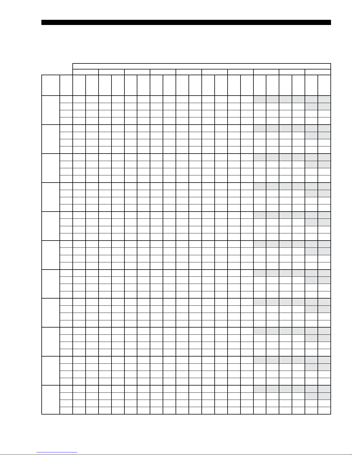
TABLE 7 –COOLING PERFORMANCE DATA* – 70 TON MODEL (CONT’D)
95°F OUTDOOR AMBIENT TEMPERATURE
ENTERING AIR DRY BULB
95°F 92°F 89°F 86°F 83°F 80°F 77°F 74°F 71°F 68°F
FORM 100.50-EG12 (918)
CFM
75 837 561 838 519 838 478 838 436 838 394 839 352 839 311
14,000
15,500
17,000
18,500
20,000
21,500
23,000
24,500
26,000
27,500
29,000
* Rated performance is at sea level. Cooling capacities are gross cooling capacity.
71 785 620 785 578 786 537 786 495 786 452 787 409 787 367 1837 325 788 284
67 734 675 734 634 735 593 735 551 736 511 736 471 737 429 737 387 737 345 738 302
62 706 706 706 695 706 685 706 675 692 608 677 541 677 501 678 460 678 419 679 378
75 854 590 854 544 855 499 855 453 855 409 856 364 856 317
71 802 654 802 609 803 564 803 518 804 455 804 392 804 358 1837 324 807 290
67 750 717 751 671 751 625 752 579 752 534 753 489 753 443 754 397 754 351 755 310
62 734 734 725 718 715 703 706 687 699 627 692 568 693 523 693 478 694 433 695 389
75 871 618 871 569 871 520 872 471 872 423 873 375 873 323
71 819 688 820 639 820 590 820 541 821 458 822 375 822 349 1837 322 822 296
67 767 759 768 708 768 658 769 607 769 557 769 508 770 458 770 408 771 358 771 309
62 762 762 743 741 724 720 706 699 707 647 708 595 708 545 709 496 709 446 710 397
75 882 647 882 593 882 539 883 486 883 434 884 382 884 327
71 830 721 830 668 830 616 831 563 832 484 833 404 833 369 1594 333 833 298
67 787 781 784 732 782 683 779 634 779 580 780 527 780 473 781 420 781 366 782 313
62 783 783 763 761 743 740 723 718 721 669 718 620 719 567 720 514 720 460 721 407
75 893 675 893 617 893 559 893 501 894 445 895 389 896 331
71 840 753 841 697 841 641 842 586 842 510 843 434 844 389 1351 344 844 300
67 806 802 801 755 795 708 790 660 790 603 790 546 791 489 791 431 792 374 793 317
62 803 803 783 781 762 759 741 737 735 692 729 646 730 589 730 531 731 474 731 417
75 904 703 904 641 904 578 904 516 905 456 906 396 907 335
71 850 785 851 726 852 667 852 608 853 536 854 463 854 409 1109 355 855 301
67 826 824 817 778 809 733 800 687 800 626 800 565 801 504 802 443 803 382 804 321
62 824 824 802 802 780 779 759 757 749 714 740 672 740 611 741 549 741 488 742 427
75 914 732 915 665 915 598 915 531 916 467 917 404 918 340
71 861 818 861 755 862 693 863 630 864 561 865 493 865 430 866 366 866 303
67 845 845 834 801 822 758 811 714 811 649 8 11 584 812 519 813 455 814 390 814 326
62 844 844 822 822 799 799 776 776 763 737 750 698 751 632 751 567 752 502 753 436
75 921 758 921 687 922 617 922 547 923 479 924 4 11 925 342
71 871 839 871 776 870 712 870 648 871 577 872 506 872 438 873 371 873 303
67 860 860 846 819 832 779 818 738 818 670 818 602 819 533 820 465 820 397 821 328
62 859 859 836 836 813 813 790 790 774 754 758 719 758 650 759 582 759 514 759 446
75 927 784 928 710 928 636 929 562 930 491 931 419 932 345
71 882 861 880 796 879 731 877 667 878 593 879 519 879 447 879 375 880 303
67 874 874 858 837 841 800 824 763 825 691 826 620 826 548 827 475 827 403 828 331
62 874 874 850 850 827 827 803 803 784 771 766 739 766 668 766 598 766 527 766 456
75 934 810 934 733 935 655 936 578 937 502 938 427 939 347
71 893 882 890 817 887 751 884 685 885 608 886 532 886 456 886 380 887 304
67 889 889 870 855 850 821 831 788 832 713 833 638 833 562 834 486 834 410 835 334
62 888 888 864 864 840 840 816 816 795 788 773 760 773 687 773 613 773 539 772 466
75 940 837 941 756 942 675 942 594 944 514 945 435 946 350
71 904 904 900 837 895 770 890 703 892 624 893 544 893 464 893 384 893 304
67 903 903 881 873 860 843 838 812 839 734 840 656 841 576 841 496 841 416 842 337
62 903 903 879 879 854 854 830 830 805 805 781 781 781 705 780 628 780 552 779 475
WB (°F)
TMBH
SMBH
TMBH
SMBH
TMBH
SMBH
TMBH
SMBH
TMBH
SMBH
TMBH
SMBH
TMBH
SMBH
TMBH
SMBH
TMBH
SMBH
TMBH
SMBH
JOHNSON CONTROLS
27
Page 28

FORM100.50-EG12 (918)
Cooling Performance Data – 70 Ton Model (Cont’d)
TABLE 7 – COOLING PERFORMANCE DATA* – 70 TON MODEL (CONT’D)
105°F OUTDOOR AMBIENT TEMPERATURE
95°F 92°F 89°F 86°F 83°F 80°F 77°F 74°F 71°F 68°F
ENTERING AIR DRY BULB
CFM
14,000
15,500
17,000
18,500
20,000
21,500
23,000
24,500
26,000
27,500
29,000
* Rated performance is at sea level. Cooling capacities are gross cooling capacity.
TMBH
WB (°F)
75 800 547 800 508 801 469 802 429 802 383 802 337 803 297
71 749 602 749 566 750 531 751 495 751 444 751 394 751 353 1277 312 752 271
67 699 660 700 618 700 577 701 536 702 509 702 483 702 434 703 385 703 337 703 288
62 680 680 672 664 665 648 657 633 651 579 644 524 644 483 645 442 645 401 645 360
75 815 576 815 532 816 488 817 443 817 395 818 348 818 303
71 765 638 765 596 766 553 766 5 11 767 452 767 393 767 354 1284 314 770 273
67 717 696 717 652 717 608 716 564 717 530 717 497 718 445 718 394 718 342 720 292
62 707 707 693 689 680 671 667 653 660 606 653 559 655 512 656 465 658 418 660 370
75 830 605 831 556 831 506 832 457 833 408 833 358 834 308
71 780 674 781 625 781 576 782 527 783 460 783 392 784 354 1291 316 784 278
67 736 732 735 685 733 639 732 592 732 552 733 5 11 733 457 733 403 734 348 734 294
62 733 733 714 713 695 693 676 672 669 633 662 594 665 540 668 487 671 434 674 380
75 841 633 841 579 842 526 843 472 843 419 844 365 845 313
71 790 707 791 653 792 599 792 545 793 479 794 414 794 369 1175 324 794 279
67 755 752 751 708 747 664 742 620 743 574 743 527 744 470 744 412 744 355 745 298
62 753 753 733 733 713 712 693 691 684 654 675 616 677 560 680 504 682 447 685 391
75 851 660 852 602 853 545 853 487 854 429 855 372 856 317
71 800 739 801 680 802 621 802 562 804 499 805 436 805 384 1059 332 805 280
67 775 773 768 731 760 690 753 648 753 595 754 542 754 482 754 422 755 362 755 302
62 773 773 753 752 732 731 711 709 699 674 688 639 690 580 691 520 693 461 695 401
75 862 688 863 626 863 564 864 501 865 440 866 379 866 321
71 811 772 811 708 812 644 813 580 814 518 815 457 816 398 943 339 816 280
67 794 793 784 754 774 715 763 676 764 617 764 558 765 495 765 432 765 369 765 306
62 793 793 772 772 750 750 729 728 715 695 700 662 702 599 703 537 704 474 705 412
75 873 716 873 649 874 583 875 516 876 451 877 386 877 325
71 821 804 821 735 822 666 823 597 825 538 826 479 826 413 826 347 827 281
67 814 814 801 777 787 741 774 704 774 639 775 573 775 508 775 442 776 376 776 310
62 814 814 791 791 769 769 746 746 730 715 713 685 714 619 714 553 715 488 716 422
75 878 742 878 672 879 602 880 532 882 463 883 394 883 328
71 832 820 831 753 830 687 829 620 830 556 832 492 832 422 832 353 832 283
67 827 827 812 793 796 759 780 725 780 657 781 589 781 520 781 451 781 382 781 313
62 827 827 804 804 781 781 759 759 739 729 720 699 721 632 721 565 721 498 721 431
75 883 768 884 694 885 621 886 547 887 475 888 402 889 331
71 844 836 841 772 838 707 835 643 836 574 838 505 837 431 837 358 837 285
67 840 840 822 809 805 777 787 745 787 675 787 606 787 533 787 460 787 387 787 315
62 840 840 817 817 794 794 771 771 749 742 728 713 727 645 727 576 727 508 727 440
75 887 794 889 717 890 640 892 562 893 486 894 410 894 334
71 856 852 851 790 846 728 841 666 842 592 843 517 843 440 843 363 843 287
67 854 854 833 825 813 795 793 766 793 694 792 622 792 545 792 469 792 393 792 317
62 853 853 830 830 806 806 783 783 759 755 735 728 734 658 734 588 733 518 732 448
75 892 820 894 739 896 659 897 578 898 498 900 418 900 337
71 868 868 861 808 854 748 847 689 848 609 849 530 849 449 848 369 848 288
67 867 867 844 840 822 814 799 787 799 712 798 638 798 558 798 478 798 399 798 319
62 867 867 843 843 819 819 795 795 769 769 742 742 741 671 740 600 739 528 738 457
SMBH
TMBH
SMBH
TMBH
SMBH
TMBH
SMBH
TMBH
SMBH
TMBH
SMBH
TMBH
SMBH
TMBH
SMBH
TMBH
SMBH
TMBH
SMBH
28
JOHNSON CONTROLS
Page 29

TABLE 7 –COOLING PERFORMANCE DATA* – 70 TON MODEL (CONT’D)
115°F OUTDOOR AMBIENT TEMPERATURE
ENTERING AIR DRY BULB
95°F 92°F 89°F 86°F 83°F 80°F 77°F 74°F 71°F 68°F
FORM 100.50-EG12 (918)
CFM
75 762 533 763 496 764 460 765 423 765 372 765 321 766 283
14,000
15,500
17,000
18,500
20,000
21,500
23,000
24,500
26,000
27,500
29,000
* Rated performance is at sea level. Cooling capacities are gross cooling capacity.
71 713 584 714 554 715 524 716 494 716 437 715 379 716 339 841 353 717 258
67 664 644 665 603 666 561 667 520 667 507 668 494 668 439 789 414 669 329 669 274
62 654 654 639 633 624 612 609 590 610 549 611 507 611 466 728 533 611 384 612 342
75 776 563 777 520 778 476 779 433 779 382 780 331 780 289
71 727 622 728 583 729 543 730 504 730 449 730 394 730 349 859 360 733 256
67 684 674 683 632 682 591 681 549 682 527 682 505 682 448 807 426 683 334 684 273
62 679 679 662 659 645 639 627 618 621 584 614 550 617 501 746 530 622 402 626 351
75 789 592 790 543 791 493 792 444 793 392 794 341 794 294
71 741 660 742 6 11 743 562 744 513 744 461 745 410 745 360 878 366 746 261
67 705 705 702 662 698 620 695 577 696 546 696 515 696 456 826 438 697 338 697 279
62 705 705 685 685 666 666 646 646 632 620 617 593 622 536 763 527 633 421 639 364
75 798 619 799 566 800 513 801 459 802 404 803 349 803 297
71 751 690 751 637 752 585 753 533 753 478 754 423 754 369 890 372 754 262
67 723 723 717 684 710 644 704 604 705 565 705 525 705 465 838 448 706 343 706 282
62 723 723 703 703 683 683 663 663 648 635 633 607 637 549 775 544 644 432 648 374
75 807 647 809 589 810 532 811 475 811 416 812 358 812 301
71 760 719 761 664 761 608 762 553 763 494 763 436 763 378 902 377 763 263
67 742 742 732 705 722 668 713 632 714 584 714 536 714 473 850 459 714 348 715 286
62 741 741 721 721 700 700 680 680 664 651 649 622 651 562 787 561 655 444 657 384
75 816 674 818 613 819 552 820 490 821 428 822 366 822 304
71 770 749 770 690 770 632 771 573 772 511 773 448 773 387 914 383 772 264
67 760 760 747 726 734 693 722 659 723 603 723 546 723 482 862 470 723 354 723 289
62 760 760 738 738 717 717 696 696 681 666 665 636 665 575 799 579 666 455 666 395
75 826 702 827 636 828 571 829 506 830 440 831 374 831 307
71 779 779 779 717 779 655 780 593 781 527 782 461 782 396 926 389 781 266
67 778 778 762 748 746 717 731 687 732 622 733 557 732 491 874 480 732 359 732 293
62 778 778 756 756 735 735 713 713 697 682 681 650 679 589 811 596 676 466 675 405
75 830 727 832 658 833 589 835 520 836 450 837 381 837 312
71 792 792 790 732 788 673 785 613 787 544 788 475 787 406 933 394 787 267
67 791 791 774 763 756 734 738 705 738 639 738 572 738 503 881 491 738 364 738 295
62 791 791 769 769 747 747 725 725 706 694 687 663 685 601 818 613 682 476 680 413
75 835 752 837 679 839 607 840 534 842 461 843 388 842 316
71 805 805 800 748 796 691 791 633 792 561 794 488 793 415 941 398 792 269
67 804 804 785 778 765 751 746 724 745 656 744 588 744 515 889 502 743 370 743 297
62 804 804 782 782 759 759 737 737 714 707 692 677 690 613 826 630 687 486 686 422
75 840 777 842 701 844 625 846 548 847 471 849 395 848 320
71 818 818 811 763 804 709 797 654 798 578 800 502 799 425 949 403 797 271
67 817 817 796 792 775 768 754 743 752 673 750 604 750 528 897 513 749 376 749 299
62 817 817 794 794 771 771 749 749 723 719 698 690 696 625 833 647 693 495 691 430
75 845 803 847 722 849 642 852 562 853 482 854 402 854 324
71 831 831 822 779 812 726 803 674 804 595 805 515 805 435 957 408 803 273
67 830 830 807 807 784 784 761 761 759 690 756 620 755 540 904 524 754 381 754 302
62 830 830 807 807 784 784 761 761 732 732 703 703 701 637 840 663 698 505 697 439
WB (°F)
TMBH
SMBH
TMBH
SMBH
TMBH
SMBH
TMBH
SMBH
TMBH
SMBH
TMBH
SMBH
TMBH
SMBH
TMBH
SMBH
TMBH
SMBH
TMBH
SMBH
JOHNSON CONTROLS
29
Page 30
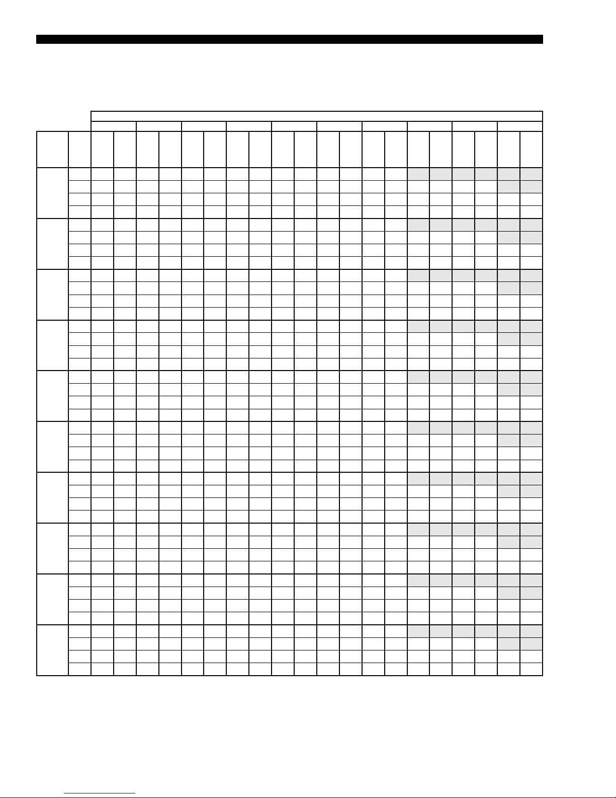
FORM100.50-EG12 (918)
Cooling Performance Data – 75 Ton Model
TABLE 8 - COOLING PERFORMANCE DATA* – 75 TON MODEL
75°F OUTDOOR AMBIENT TEMPERATURE
95°F 92°F 89°F 86°F 83°F 80°F 77°F 74°F 71°F 68°F
ENTERING AIR DRY BULB
CFM
15,500
17,000
18,500
20,000
21,500
23,000
24,500
26,000
27,500
29,000
* Rated performance is at sea level. Cooling capacities are gross cooling capacity.
TMBH
WB (°F)
75 1007 614 1006 574 1006 534 1005 494 1005 442 1005 389 1005 359
71 941 689 941 644 940 599 940 554 939 516 938 479 938 429 938 379 938 329
67 878 763 878 713 878 664 877 614 877 569 876 524 875 479 875 434 875 389 874 344
62 820 838 814 793 809 748 803 703 803 659 803 614 802 570 801 527 800 483 800 439
75 1029 657 1029 632 1028 607 1027 583 1027 494 1026 405 1349 489
71 963 731 962 736 962 741 961 746 960 613 960 479 959 430 959 381 959 332
67 900 804 899 754 899 704 898 653 897 603 897 553 896 503 896 452 895 402 895 351
62 852 903 843 851 833 799 824 747 823 692 823 637 822 587 821 537 820 487 819 437
75 1045 686 1045 650 1044 615 1043 580 1042 496 1041 413 1283 459
71 979 763 978 750 977 737 977 723 976 607 975 490 975 436 974 382 974 329
67 916 847 915 792 914 737 913 682 913 627 912 573 9 11 518 910 463 910 408 909 353
62 878 959 865 901 852 842 839 783 838 725 837 667 836 613 835 558 834 504 833 450
75 1061 715 1060 669 1059 623 1059 577 1058 499 1057 420 1218 429
71 994 796 994 764 993 733 992 701 991 601 990 501 990 442 989 384 989 326
67 933 890 931 830 930 771 929 7 11 928 651 927 592 926 533 925 474 924 415 924 356
62 904 1016 887 950 871 885 855 820 853 759 852 697 851 639 850 580 849 521 848 463
75 1077 744 1076 687 1075 630 1074 574 1073 501 1072 428 1153 399
71 1010 829 1009 779 1009 728 1008 678 1007 595 1006 511 1005 448 1004 386 1004 323
67 949 932 947 868 946 804 944 740 943 676 942 6 11 941 548 940 485 939 421 938 358
62 929 1072 909 1000 890 928 870 856 868 792 866 727 865 664 864 601 863 539 862 476
75 1093 773 1092 706 1091 638 1090 571 1089 503 1087 435 1087 369
71 1026 862 1025 793 1024 724 1024 655 1022 589 1021 522 1020 455 1020 387 1019 320
67 966 975 963 906 961 837 959 768 958 700 957 631 956 563 955 495 954 428 953 360
62 955 1128 932 1050 909 971 885 893 883 825 881 757 880 690 878 623 877 556 876 489
75 1103 802 1102 730 1101 658 1100 586 1098 513 1097 440 1097 369
71 1036 901 1035 828 1034 755 1033 682 1032 610 1031 539 1030 467 1029 396 1028 324
67 982 1020 977 946 973 873 969 799 968 726 967 653 962 579 956 505 951 431 945 357
62 974 1182 949 1100 924 1017 900 934 895 861 891 788 885 713 880 638 874 564 868 489
75 1113 830 1112 754 1111 677 1110 600 1108 522 1106 444 1106 369
71 1046 941 1045 863 1044 786 1043 708 1042 632 1040 556 1040 480 1039 404 1038 328
67 998 1064 992 986 985 908 979 829 978 752 977 675 967 595 957 514 947 434 938 354
62 992 1236 966 1149 940 1063 914 976 907 897 900 818 890 736 881 654 871 572 861 489
75 1123 859 1122 778 1121 697 1120 615 1118 532 111 6 449 1116 369
71 1057 980 1056 898 1054 817 1053 735 1052 654 1050 574 1049 493 1048 413 1047 332
67 1014 1109 1006 1026 997 943 989 860 988 779 986 697 972 6 11 958 524 944 437 930 350
62 1011 1290 984 1199 956 1108 929 1017 919 933 910 849 896 759 882 669 868 579 854 490
75 1133 888 1132 802 1131 716 1130 630 1128 542 1126 454 1125 370
71 1067 1019 1066 933 1064 848 1063 762 1062 676 1060 591 1059 506 1058 421 1057 336
67 1030 1154 1020 1066 1009 978 999 891 997 805 996 720 978 627 959 533 941 440 923 347
62 1030 1344 1001 1249 972 1154 943 1059 931 969 920 879 901 782 883 685 865 587 847 490
SMBH
TMBH
SMBH
TMBH
SMBH
TMBH
SMBH
TMBH
SMBH
TMBH
SMBH
TMBH
SMBH
TMBH
SMBH
TMBH
SMBH
TMBH
SMBH
30
JOHNSON CONTROLS
Page 31

TABLE 8 – COOLING PERFORMANCE DATA* – 75 TON MODEL (CONT’D)
85°F OUTDOOR AMBIENT TEMPERATURE
ENTERING AIR DRY BULB
95°F 92°F 89°F 86°F 83°F 80°F 77°F 74°F 71°F 68°F
FORM 100.50-EG12 (918)
CFM
75 972 606 971 561 970 516 969 471 969 427 969 382 969 344
15,500
17,000
18,500
20,000
21,500
23,000
24,500
26,000
27,500
29,000
* Rated performance is at sea level. Cooling capacities are gross cooling capacity.
71 908 674 907 629 907 584 906 539 906 498 905 458 1389 410 1387 362 904 314
67 847 741 847 693 846 646 846 599 845 554 845 509 859 471 874 434 889 397 904 359
62 797 823 790 781 782 738 774 696 774 647 774 599 789 562 805 525 820 488 835 452
75 992 642 992 604 991 566 990 529 989 460 989 391 1150 406
71 928 716 928 693 927 670 926 647 925 556 924 464 1399 414 1398 364 924 314
67 867 789 867 739 866 689 866 639 865 588 864 538 863 487 863 437 862 387 862 337
62 828 891 817 838 805 784 794 731 793 677 793 624 792 574 791 524 790 474 789 424
75 1007 671 1007 626 1006 581 1005 536 1004 467 1003 399 1124 393
71 943 752 943 718 942 683 941 649 940 563 939 478 1295 423 1294 369 938 315
67 884 832 883 777 881 723 880 668 879 613 878 558 878 503 877 449 876 394 875 340
62 853 947 838 887 824 827 809 767 808 710 806 653 805 598 804 544 803 489 802 435
75 1023 701 1022 648 1021 596 1020 543 1019 475 1018 406 1099 380
71 958 788 958 742 957 697 956 651 955 571 954 492 1191 433 1190 374 952 315
67 900 875 898 816 896 757 894 698 894 638 893 579 892 520 891 461 890 402 889 343
62 878 1003 860 937 842 870 824 804 822 743 820 682 819 623 818 564 817 504 816 445
75 1038 730 1037 670 1036 610 1035 550 1033 482 1032 414 1073 366
71 973 824 973 767 972 710 971 653 970 579 968 506 1086 442 1086 379 967 315
67 917 918 914 855 9 11 791 909 728 908 663 907 599 906 536 905 472 904 409 903 346
62 903 1059 882 986 861 913 840 841 837 776 834 711 833 647 832 583 830 520 829 456
75 1053 760 1052 692 1051 625 1049 557 1048 490 1047 422 1047 353
71 988 860 988 791 987 723 986 655 984 587 983 520 982 452 981 383 981 315
67 933 962 930 894 926 825 923 757 922 689 922 620 920 552 919 484 918 416 917 349
62 927 1115 903 1036 879 957 855 877 852 808 848 740 847 671 845 603 844 535 842 466
75 1062 788 1061 717 1059 645 1058 573 1057 500 1055 428 1055 355
71 998 896 997 823 996 751 995 678 993 606 992 534 991 461 990 389 989 316
67 949 1007 944 933 938 859 932 786 931 713 930 640 927 567 923 494 920 421 916 348
62 945 1168 920 1085 895 1001 869 918 863 843 857 769 853 694 850 620 846 546 842 472
75 1071 817 1069 741 1068 665 1067 588 1065 511 1064 434 1063 356
71 1007 932 1006 855 1005 778 1003 701 1002 625 1000 548 999 471 998 394 997 317
67 966 1051 958 972 949 893 941 814 940 737 939 660 933 582 928 503 922 425 916 347
62 963 1221 936 1133 910 1046 884 958 875 878 866 798 860 717 854 637 848 557 842 477
75 1079 846 1078 765 1077 684 1076 604 1074 521 1072 439 1072 358
71 1016 968 1015 887 1014 806 1012 725 1011 643 1009 562 1008 480 1007 399 1006 318
67 982 1096 971 1012 961 927 950 843 949 761 948 680 940 596 932 513 924 429 916 346
62 980 1274 953 1182 926 1090 898 999 886 913 874 827 866 740 858 654 850 568 842 482
75 1088 875 1087 790 1086 704 1085 619 1083 532 1081 445 1080 360
71 1026 1004 1024 919 1023 833 1021 748 1020 662 1018 575 1017 490 1015 405 1014 319
67 998 1141 985 1051 972 961 959 871 958 786 956 700 946 6 11 936 522 926 433 916 344
62 998 1327 969 1231 941 1135 913 1039 898 947 883 856 873 763 863 671 852 579 842 487
WB (°F)
TMBH
SMBH
TMBH
SMBH
TMBH
SMBH
TMBH
SMBH
TMBH
SMBH
TMBH
SMBH
TMBH
SMBH
TMBH
SMBH
TMBH
SMBH
TMBH
SMBH
JOHNSON CONTROLS
31
Page 32

FORM100.50-EG12 (918)
Cooling Performance Data – 75 Ton Model (Cont’d)
TABLE 8 – COOLING PERFORMANCE DATA* – 75 TON MODEL (CONT’D)
95°F OUTDOOR AMBIENT TEMPERATURE
95°F 92°F 89°F 86°F 83°F 80°F 77°F 74°F 71°F 68°F
ENTERING AIR DRY BULB
CFM
15,500
17,000
18,500
20,000
21,500
23,000
24,500
26,000
27,500
29,000
* Rated performance is at sea level. Cooling capacities are gross cooling capacity.
TMBH
WB (°F)
75 936 599 935 549 935 499 934 449 933 412 933 374 933 329
71 875 659 874 614 874 569 873 524 872 480 872 437 1839 391 1837 345 871 299
67 816 718 816 674 815 629 815 584 814 539 813 494 843 464 873 434 903 404 933 374
62 775 808 765 768 755 728 746 689 745 636 745 584 777 554 808 524 840 494 871 464
75 955 627 954 576 954 525 953 474 952 425 951 376 952 323
71 894 701 893 650 892 599 892 548 890 498 889 448 1839 398 1837 347 889 297
67 835 773 834 723 834 674 833 624 832 573 831 522 831 472 830 422 829 372 828 322
62 804 880 791 825 777 769 764 714 763 662 762 6 11 761 561 760 5 11 759 462 758 412
75 969 656 968 601 967 546 966 491 962 436 958 381 965 327
71 907 737 906 682 906 626 905 571 901 516 896 460 1610 406 1611 352 901 298
67 851 817 849 762 848 707 846 652 842 596 838 540 839 486 840 432 840 379 841 325
62 828 935 811 874 795 812 779 751 774 694 769 636 770 583 770 529 770 475 770 422
75 982 686 981 626 980 567 980 508 972 447 965 386 977 330
71 921 772 920 713 919 653 918 594 9 11 533 904 472 1382 414 1385 356 914 298
67 867 861 865 801 862 741 859 681 852 620 845 559 847 501 849 443 851 385 853 327
62 851 991 832 923 813 856 793 788 785 725 776 662 778 604 779 547 781 489 782 431
75 996 715 995 652 994 588 993 525 982 458 972 390 990 334
71 934 808 933 744 933 681 932 617 921 550 911 484 1153 422 1158 361 927 299
67 883 905 880 839 876 774 872 709 862 643 852 577 856 515 859 454 862 392 865 330
62 874 1046 852 972 830 899 808 825 796 756 783 687 786 626 789 564 792 503 794 441
75 1009 744 1008 677 1007 609 1006 542 992 469 978 395 1003 338
71 948 844 947 776 946 708 945 640 931 567 918 495 925 430 932 365 939 300
67 900 948 895 878 890 808 885 737 872 666 859 595 864 530 869 464 873 399 878 333
62 898 1102 873 1022 848 942 823 862 807 787 790 713 794 647 798 582 802 516 806 451
75 1018 774 1017 702 1016 630 1015 558 1004 482 993 406 1011 341
71 957 880 956 808 955 735 954 663 943 587 932 5 11 937 441 942 371 947 300
67 916 993 909 918 901 842 894 766 884 691 874 617 877 546 880 476 883 406 885 335
62 915 1154 889 1070 864 985 838 901 821 822 804 743 807 672 809 601 812 530 814 459
75 1027 803 1026 727 1024 651 1023 575 1015 495 1007 416 1019 344
71 966 916 965 840 963 763 962 687 954 607 947 528 950 452 952 377 955 301
67 933 1038 923 957 913 876 902 794 895 716 888 638 889 563 891 488 892 413 893 337
62 932 1206 905 1118 879 1029 853 941 836 856 818 772 819 696 820 620 821 544 822 468
75 1035 833 1034 752 1033 672 1032 591 1027 509 1022 426 1027 347
71 975 952 973 872 972 791 971 710 966 627 961 544 962 463 963 382 963 302
67 950 1084 937 997 924 910 911 823 907 741 902 659 902 579 902 499 901 419 901 340
62 949 1258 922 1166 895 1073 868 980 850 891 832 802 832 721 831 639 831 558 830 476
75 1044 863 1043 778 1042 693 1040 608 1038 522 1036 437 1034 350
71 984 989 982 904 981 819 979 734 977 647 976 560 974 474 973 388 971 302
67 966 1129 951 1036 935 944 920 851 918 766 917 680 915 596 913 511 9 11 426 909 342
62 966 1311 938 1214 910 111 6 883 1019 864 926 846 832 844 745 842 658 840 571 838 484
SMBH
TMBH
SMBH
TMBH
SMBH
TMBH
SMBH
TMBH
SMBH
TMBH
SMBH
TMBH
SMBH
TMBH
SMBH
TMBH
SMBH
TMBH
SMBH
32
JOHNSON CONTROLS
Page 33

TABLE 8 – COOLING PERFORMANCE DATA* – 75 TON MODEL (CONT’D)
105°F OUTDOOR AMBIENT TEMPERATURE
ENTERING AIR DRY BULB
95°F 92°F 89°F 86°F 83°F 80°F 77°F 74°F 71°F 68°F
FORM 100.50-EG12 (918)
CFM
75 894 584 893 536 893 489 892 442 891 400 890 358 891 314
15,500
17,000
18,500
20,000
21,500
23,000
24,500
26,000
27,500
29,000
* Rated performance is at sea level. Cooling capacities are gross cooling capacity.
71 836 653 835 605 834 557 833 509 833 461 832 413 1315 370 1314 327 831 284
67 779 732 779 680 778 628 778 576 777 524 776 471 791 436 805 400 820 365 835 329
62 727 835 722 781 716 728 711 674 711 625 710 576 726 537 741 498 756 458 771 419
75 912 611 911 560 910 509 909 459 908 409 907 360 907 307
71 853 684 852 633 851 583 851 533 849 482 848 432 1323 381 1322 331 847 281
67 797 756 796 706 795 656 794 607 793 556 793 505 792 455 791 405 790 355 789 305
62 775 867 760 810 744 752 728 695 727 644 726 593 725 543 724 493 723 443 722 393
75 924 641 924 586 923 531 922 476 921 422 919 367 920 310
71 866 720 865 665 864 610 863 556 862 501 861 446 1216 391 1215 336 859 282
67 814 801 812 746 809 691 807 635 806 581 805 526 804 471 803 416 802 361 801 307
62 798 921 780 858 762 796 744 733 741 677 738 621 737 567 736 512 735 458 733 404
75 937 671 936 6 11 935 552 934 493 933 434 932 375 932 313
71 879 756 878 697 877 638 876 578 875 519 873 460 1110 401 1109 342 871 283
67 832 845 827 785 823 725 819 664 818 605 817 547 816 487 815 428 814 368 813 309
62 821 975 800 907 780 839 760 771 755 710 750 649 749 591 748 532 746 473 745 414
75 950 701 949 637 948 573 947 509 945 446 944 383 944 317
71 892 792 891 729 890 665 889 601 887 538 886 474 1004 4 11 1002 347 883 283
67 849 890 843 825 837 759 832 693 831 630 830 568 828 503 827 439 826 375 824 3 11
62 843 1030 821 956 798 882 775 808 769 743 763 678 761 615 759 551 758 488 756 425
75 963 731 962 663 961 594 960 526 958 459 956 391 956 320
71 905 828 903 760 902 692 901 624 900 556 898 489 897 421 896 352 895 284
67 866 935 859 864 851 793 844 722 843 655 842 589 840 520 839 451 837 382 836 313
62 866 1084 841 1005 816 925 791 846 783 776 775 706 773 639 771 571 770 503 768 435
75 970 760 969 687 968 615 967 543 965 470 963 398 962 324
71 913 865 912 792 910 719 909 647 907 574 905 502 904 429 903 357 902 284
67 882 979 872 903 862 826 851 750 850 678 849 607 847 534 846 461 844 388 842 315
62 881 1137 856 1053 830 969 805 885 794 809 782 733 780 661 778 589 776 516 774 444
75 978 789 977 712 975 635 974 559 972 482 970 405 969 327
71 922 901 920 824 918 746 916 669 914 592 913 515 9 11 438 910 361 908 284
67 898 1023 885 942 872 860 859 778 858 702 856 625 854 548 852 471 850 394 849 317
62 897 1190 871 1101 845 1013 819 924 804 842 790 761 788 683 786 606 783 529 781 452
75 985 818 984 737 983 656 982 575 979 493 977 412 976 331
71 930 937 928 855 926 773 923 692 922 610 920 529 918 447 916 366 915 284
67 913 1068 898 980 882 893 867 806 865 725 863 644 861 563 859 481 857 400 855 319
62 913 1242 886 1149 859 1056 833 963 815 876 798 788 795 706 793 624 790 542 788 461
75 993 847 991 762 990 676 989 591 986 505 984 419 982 335
71 939 973 936 887 933 800 931 714 929 628 927 542 925 456 923 370 921 284
67 929 1112 910 1019 892 927 874 835 872 748 871 662 868 577 866 491 864 406 861 321
62 928 1295 901 1198 874 1100 847 1003 826 909 805 815 802 728 800 642 797 556 795 469
WB (°F)
TMBH
SMBH
TMBH
SMBH
TMBH
SMBH
TMBH
SMBH
TMBH
SMBH
TMBH
SMBH
TMBH
SMBH
TMBH
SMBH
TMBH
SMBH
TMBH
SMBH
JOHNSON CONTROLS
33
Page 34

FORM100.50-EG12 (918)
Cooling Performance Data – 75 Ton Model (Cont’d)
TABLE 8 – COOLING PERFORMANCE DATA* – 75 TON MODEL (CONT’D)
115°F OUTDOOR AMBIENT TEMPERATURE
95°F 92°F 89°F 86°F 83°F 80°F 77°F 74°F 71°F 68°F
ENTERING AIR DRY BULB
CFM
15,500
17,000
18,500
20,000
21,500
23,000
24,500
26,000
27,500
29,000
* Rated performance is at sea level. Cooling capacities are gross cooling capacity.
TMBH
WB (°F)
75 852 569 851 524 850 479 850 434 848 388 847 342 848 299
71 796 647 796 596 795 545 794 494 793 442 792 389 792 349 791 309 791 269
67 742 745 742 686 741 628 740 569 739 508 738 448 738 407 737 366 737 325 736 284
62 679 863 678 795 677 727 677 659 676 614 676 569 675 520 674 471 673 423 672 374
75 868 594 867 544 866 494 865 443 864 393 863 343 863 291
71 812 666 811 617 810 567 810 517 808 466 807 415 807 365 806 315 806 264
67 759 739 758 689 757 639 756 589 755 538 754 488 753 437 752 387 751 337 750 287
62 747 854 729 795 710 735 692 676 691 625 690 575 689 524 688 474 687 424 686 374
75 879 624 878 569 877 514 876 460 875 405 874 351 874 294
71 823 703 822 648 822 594 821 540 819 485 818 429 817 375 817 320 816 265
67 777 784 773 729 770 674 766 619 765 563 764 508 768 455 772 402 775 349 779 297
62 768 907 748 844 728 780 709 716 705 660 701 603 704 550 707 498 710 445 713 392
75 891 654 889 594 888 535 887 476 886 417 884 358 884 297
71 835 739 834 680 833 621 832 563 830 503 829 443 828 384 827 325 826 267
67 795 830 789 769 783 709 777 648 776 588 775 528 783 472 791 417 799 361 807 306
62 789 961 767 893 746 824 725 756 718 694 712 632 719 576 726 521 733 466 741 410
75 902 683 901 620 900 556 898 492 897 429 895 366 894 301
71 846 775 845 712 844 649 843 586 841 521 840 457 839 394 838 331 836 268
67 813 876 805 810 796 743 788 677 787 613 786 548 798 490 811 432 823 373 835 315
62 809 1015 787 942 764 868 741 795 732 728 722 660 734 602 745 544 757 486 768 428
75 913 713 912 645 9 11 577 910 509 907 441 905 373 905 304
71 858 811 857 743 855 676 854 609 852 540 850 471 849 403 848 336 847 269
67 831 922 820 850 810 778 799 706 798 637 796 569 813 507 830 446 847 385 864 324
62 830 1068 806 991 782 913 757 835 745 762 733 689 749 628 764 567 780 507 796 446
75 920 743 919 670 918 598 916 525 914 452 912 380 9 11 308
71 867 847 865 775 863 703 861 630 859 557 857 484 856 412 854 340 853 268
67 846 965 833 888 820 811 806 734 805 661 804 587 815 520 827 453 839 385 851 318
62 845 1121 821 1038 796 956 771 873 756 794 741 716 752 649 763 582 774 515 784 448
75 927 772 926 695 925 618 923 541 921 464 919 387 917 312
71 876 884 873 807 871 729 868 652 866 574 864 497 863 421 861 344 859 267
67 861 1008 845 926 829 844 814 762 812 684 811 606 818 533 825 459 832 386 839 312
62 860 1174 835 1086 810 998 784 910 766 827 749 743 755 670 761 597 767 523 773 450
75 934 802 933 721 932 639 930 558 928 476 925 394 924 316
71 885 921 882 838 878 756 875 673 873 592 871 510 869 429 867 348 865 267
67 876 1052 858 964 839 877 821 790 819 708 818 625 820 545 822 466 824 386 827 306
62 875 1227 849 1134 823 1041 797 948 777 859 756 771 758 691 759 6 11 761 532 762 452
75 942 832 940 746 939 660 937 574 935 487 932 400 930 319
71 894 958 890 870 886 782 882 694 880 609 878 524 876 438 874 352 871 266
67 891 1095 870 1003 849 910 828 818 826 731 825 644 822 558 819 472 817 386 814 300
62 890 1280 864 1182 837 1084 811 986 787 892 764 798 761 712 758 626 754 540 751 454
SMBH
TMBH
SMBH
TMBH
SMBH
TMBH
SMBH
TMBH
SMBH
TMBH
SMBH
TMBH
SMBH
TMBH
SMBH
TMBH
SMBH
TMBH
SMBH
34
JOHNSON CONTROLS
Page 35

Cooling Performance Data – 80 Ton Model
TABLE 9 - COOLING PERFORMANCE DATA* – 80 TON MODEL
75°F OUTDOOR AMBIENT TEMPERATURE
ENTERING AIR DRY BULB
95°F 92°F 89°F 86°F 83°F 80°F 77°F 74°F 71°F 68°F
FORM 100.50-EG12 (918)
CFM
75 1031 623 1031 579 1031 536 892 442 1030 449 1030 406 1030 362
15,000
17,000
19,000
21,000
23,000
25,000
27,000
29,000
31,000
33,000
* Rated performance is at sea level. Cooling capacities are gross cooling capacity.
71 964 710 963 666 963 623 833 509 962 529 961 478 961 435 961 391 962 348
67 899 753 898 710 898 666 778 576 897 579 897 536 897 492 897 449 897 406 896 362
62 834 840 830 797 827 753 711 674 823 659 822 608 822 565 821 521 820 478 820 435
75 1064 668 1064 618 1065 569 909 459 1063 468 1062 417 1062 368
71 996 744 995 693 994 643 851 533 993 543 993 492 941 421 889 349 838 277
67 930 818 930 767 929 717 794 607 928 616 927 566 927 516 927 466 927 416 927 366
62 872 918 866 864 859 810 728 695 851 707 851 657 850 606 850 556 849 505 848 455
75 1085 708 1085 652 1085 596 922 476 1083 484 1082 427 1082 372
71 1016 792 1016 736 1015 679 863 556 1014 567 1013 511 974 439 935 367 896 295
67 952 875 951 819 950 763 807 635 948 650 947 594 947 538 947 482 946 426 946 371
62 907 991 896 930 884 868 744 733 871 750 870 694 869 638 869 582 868 525 867 469
75 1105 748 1105 686 1105 624 934 493 1103 500 1102 438 1103 377
71 1037 840 1036 778 1035 716 876 578 1034 592 1033 530 1007 457 981 385 955 313
67 975 933 973 870 971 808 819 664 968 684 967 622 967 561 966 499 966 437 965 375
62 941 1065 926 995 910 926 760 771 891 794 889 731 888 669 888 607 887 545 886 483
75 1126 788 1126 720 1125 652 947 509 1123 516 1122 448 1123 382
71 1058 888 1057 820 1056 752 889 601 1054 616 1053 549 1040 476 1027 403 1014 330
67 997 990 994 922 991 854 832 693 988 718 987 650 987 583 986 515 985 447 985 379
62 976 1138 955 1061 935 984 775 808 911 838 908 769 907 701 906 633 905 565 905 498
75 1147 828 1146 754 1145 680 960 526 1143 532 1143 459 1143 386
71 1078 937 1077 863 1077 789 901 624 1075 641 1074 567 1073 494 1073 421 1073 348
67 1019 1048 1016 974 1012 900 844 722 1008 752 1007 678 1006 605 1006 531 1005 457 1004 384
62 1011 1212 985 1127 960 1041 791 846 931 881 928 806 927 733 925 659 924 585 923 512
75 1159 867 1158 787 1157 707 967 543 1155 548 1154 468 1155 390
71 1090 984 1089 904 1088 824 909 647 1086 664 1085 585 1085 505 1085 426 1084 347
67 1040 1106 1033 1025 1027 944 851 750 1020 783 1019 704 1018 624 1017 545 1016 465 1015 386
62 1033 1283 1007 1191 980 1099 805 885 946 925 939 843 938 763 937 684 935 604 934 525
75 1171 906 1170 820 1169 735 974 559 1167 563 1166 478 1166 394
71 1102 1031 1101 945 1100 859 916 669 1098 688 1097 602 1096 517 1096 431 1096 346
67 1061 1164 1051 1076 1042 988 859 778 1031 815 1030 730 1029 644 1028 559 1027 473 1026 388
62 1056 1353 1028 1255 1000 1157 819 924 961 970 951 880 949 794 948 709 947 623 945 538
75 1182 946 1181 854 1180 762 982 575 1178 579 1177 488 1177 398
71 1115 1078 1113 986 1112 894 923 692 1109 7 11 1108 620 1108 528 1107 437 1107 345
67 1081 1223 1069 1128 1056 1033 867 806 1043 846 1042 755 1041 664 1040 573 1039 481 1037 390
62 1079 1424 1049 1320 1020 1216 833 963 977 1014 962 916 961 825 959 734 958 642 956 551
75 1194 985 1193 887 1192 789 989 591 1190 594 1188 497 1189 402
71 1127 1125 1125 1027 1124 929 931 714 1121 735 1120 637 1119 540 1119 442 1118 344
67 1102 1281 1087 1179 1071 1077 874 835 1055 878 1054 781 1052 684 1051 586 1050 489 1049 392
62 1101 1495 1071 1384 1040 1274 847 1003 992 1058 973 953 972 856 970 758 969 661 967 564
WB (°F)
TMBH
SMBH
TMBH
SMBH
TMBH
SMBH
TMBH
SMBH
TMBH
SMBH
TMBH
SMBH
TMBH
SMBH
TMBH
SMBH
TMBH
SMBH
TMBH
SMBH
JOHNSON CONTROLS
35
Page 36

FORM100.50-EG12 (918)
Cooling Performance Data – 80 Ton Model (Cont’d)
TABLE 9 – COOLING PERFORMANCE DATA* – 80 TON MODEL (CONT’D)
85°F OUTDOOR AMBIENT TEMPERATURE
95°F 92°F 89°F 86°F 83°F 80°F 77°F 74°F 71°F 68°F
ENTERING AIR DRY BULB
CFM
15,000
17,000
19,000
21,000
23,000
25,000
27,000
29,000
31,000
33,000
* Rated performance is at sea level. Cooling capacities are gross cooling capacity.
TMBH
WB (°F)
75 996 608 996 565 995 521 995 478 995 435 994 391 995 348
71 931 688 930 647 930 606 929 565 929 514 928 464 928 418 928 372 929 326
67 868 746 868 700 868 654 867 608 867 569 866 529 866 483 866 438 866 393 866 348
62 810 833 805 787 800 741 795 695 794 648 794 601 793 556 793 5 11 792 465 791 420
75 1026 653 1026 603 1026 553 1026 503 1020 453 1015 403 1024 353
71 960 729 960 679 959 628 958 578 953 530 947 482 1390 419 1363 357 880 295
67 897 803 897 752 896 702 895 652 890 606 884 560 886 508 889 455 891 403 894 350
62 850 906 841 851 831 796 821 741 816 696 811 650 812 598 814 545 816 492 818 439
75 1046 693 1046 637 1045 581 1045 525 1041 469 1036 414 1044 358
71 980 777 979 721 978 665 978 608 973 554 969 500 1301 434 1281 369 918 304
67 920 860 918 804 916 747 914 691 910 638 905 585 907 527 909 469 910 412 912 354
62 883 979 869 916 855 854 842 791 837 738 831 685 832 627 834 569 835 511 836 453
75 1065 733 1065 671 1065 609 1064 547 1061 486 1058 424 1063 362
71 1000 826 999 763 998 701 997 639 994 578 991 517 1212 449 1198 381 956 313
67 943 918 940 855 937 793 934 730 930 670 927 610 928 547 929 484 929 421 930 358
62 916 1052 898 982 880 9 11 862 841 857 781 852 720 853 657 853 593 853 530 853 467
75 1085 774 1084 705 1084 637 1083 569 1081 502 1079 434 1082 367
71 1019 874 1018 806 1017 738 1017 670 1014 602 1012 535 1123 464 1116 393 995 322
67 965 976 961 907 957 838 953 769 951 702 949 634 949 566 949 498 949 429 949 361
62 949 1125 927 1047 904 969 882 891 878 823 873 755 873 686 872 618 872 549 871 481
75 1105 814 1104 740 1103 665 1102 591 1102 518 1101 444 1101 372
71 1039 922 1038 848 1037 774 1036 700 1035 626 1034 553 1034 479 1033 405 1033 331
67 988 1033 982 958 977 884 972 809 971 734 970 659 969 585 969 512 968 438 967 365
62 982 1197 956 111 2 929 1027 902 942 898 865 894 789 893 716 891 642 890 569 889 495
75 1115 853 1115 773 1114 693 1113 613 1112 533 1111 454 1111 375
71 1051 969 1049 889 1048 809 1046 729 1045 650 1044 570 1044 490 1043 410 1043 331
67 1008 1092 999 1010 991 928 982 846 982 766 981 685 980 606 979 526 978 447 977 367
62 1003 1268 976 1176 949 1085 921 993 913 910 904 826 903 747 902 667 900 587 899 508
75 1126 892 1125 806 1124 720 1123 634 1122 549 1121 463 1121 379
71 1062 1016 1060 930 1059 845 1057 759 1056 673 1055 588 1054 502 1054 416 1053 330
67 1028 1151 1016 1062 1005 973 993 884 992 798 991 712 990 627 989 541 988 456 987 370
62 1025 1338 996 1240 968 1143 940 1045 927 954 915 863 913 778 912 692 910 606 909 521
75 1137 931 1136 839 1135 748 1134 656 1132 564 1131 473 1131 382
71 1074 1063 1072 972 1069 880 1067 788 1066 697 1065 605 1064 514 1064 422 1063 330
67 1048 1210 1033 111 4 1018 1018 1004 922 1002 830 1001 738 1000 647 999 556 998 464 997 373
62 1046 1408 1017 1305 988 1201 959 1097 942 998 925 900 924 808 922 717 920 625 918 534
75 1147 970 1146 873 1145 775 1144 677 1143 580 1141 483 1141 386
71 1085 1111 1083 1013 1080 915 1078 817 1077 720 1075 623 1075 525 1074 428 1073 330
67 1068 1268 1050 1165 1032 1062 1014 959 1013 862 1012 765 1010 668 1009 570 1008 473 1006 376
62 1067 1479 1037 1369 1007 1259 977 1149 957 1043 936 937 934 839 932 742 930 644 928 547
SMBH
TMBH
SMBH
TMBH
SMBH
TMBH
SMBH
TMBH
SMBH
TMBH
SMBH
TMBH
SMBH
TMBH
SMBH
TMBH
SMBH
TMBH
SMBH
36
JOHNSON CONTROLS
Page 37

TABLE 9 – COOLING PERFORMANCE DATA* – 80 TON MODEL (CONT’D)
95°F OUTDOOR AMBIENT TEMPERATURE
ENTERING AIR DRY BULB
95°F 92°F 89°F 86°F 83°F 80°F 77°F 74°F 71°F 68°F
FORM 100.50-EG12 (918)
CFM
75 961 594 960 550 960 507 960 464 959 420 959 377 959 333
15,000
17,000
19,000
21,000
23,000
25,000
27,000
29,000
31,000
33,000
* Rated performance is at sea level. Cooling capacities are gross cooling capacity.
71 898 666 897 628 897 589 897 550 896 500 895 449 895 401 895 352 896 304
67 838 739 837 690 837 642 837 594 836 558 836 521 835 474 835 427 835 380 835 333
62 787 826 780 777 773 729 766 681 766 637 765 594 765 547 764 500 764 453 763 406
75 988 639 988 588 987 538 986 488 977 439 969 390 987 338
71 925 714 924 664 923 613 923 563 912 517 902 471 1839 418 1837 365 922 312
67 864 788 864 738 863 687 862 637 851 595 840 554 845 499 850 444 856 390 861 335
62 828 895 816 838 803 782 791 726 780 685 770 644 775 589 779 534 783 479 788 424
75 1006 678 1005 622 1005 566 1004 509 997 454 990 399 1004 343
71 943 762 942 706 941 649 940 593 932 540 924 487 1627 429 1625 371 939 312
67 887 846 884 789 882 732 880 675 871 625 863 576 867 517 872 457 877 398 881 339
62 859 967 843 903 827 840 811 776 802 726 792 677 801 620 809 562 818 505 826 447
75 1024 718 1023 655 1023 593 1022 531 1017 470 1012 409 1021 348
71 960 810 960 748 959 685 958 623 952 563 947 504 1415 440 1414 376 956 313
67 909 905 905 841 901 777 897 713 891 656 885 598 889 534 893 471 897 407 902 344
62 890 1039 870 968 851 897 832 826 823 768 814 710 827 650 839 590 852 531 865 471
75 1042 757 1041 689 1040 621 1040 553 1036 485 1033 418 1038 353
71 978 857 977 789 977 721 976 653 972 586 969 520 1203 451 1202 382 973 313
67 931 963 926 892 920 822 914 751 9 11 686 908 620 911 552 915 484 918 416 922 348
62 920 1111 898 1033 875 955 853 877 844 809 836 742 853 680 870 619 887 557 904 495
75 1059 797 1059 723 1058 649 1057 575 1056 501 1055 427 1055 357
71 996 905 995 831 994 757 994 683 993 610 991 536 991 462 991 388 990 314
67 954 1021 946 944 939 867 932 789 931 716 930 642 933 570 936 497 939 425 942 352
62 951 1183 925 1098 899 1012 873 927 865 851 857 775 879 711 900 647 921 583 942 519
75 1070 836 1069 757 1068 677 1067 597 1066 517 1064 438 1064 360
71 1008 953 1006 873 1005 793 1004 713 1002 634 1001 554 1001 474 1000 394 1000 314
67 974 1080 963 996 953 912 942 828 941 748 940 669 942 590 944 512 946 433 948 354
62 971 1253 945 1162 918 1070 891 979 879 895 868 8 11 883 739 898 666 914 594 929 522
75 1080 876 1079 790 1078 705 1077 619 1076 533 1074 448 1074 363
71 1020 1001 1018 915 1016 829 1014 743 1012 658 1011 572 1011 486 1010 401 1009 315
67 994 1138 980 1048 966 957 952 866 951 781 950 696 951 6 11 952 526 953 441 953 356
62 992 1323 964 1225 937 1128 909 1031 893 939 878 848 887 767 897 686 906 605 916 524
75 1090 916 1089 824 1088 733 1087 641 1086 549 1084 458 1084 367
71 1032 1048 1029 957 1026 865 1024 773 1022 682 1021 590 1020 499 1020 407 1019 315
67 1014 1197 997 1100 979 1002 962 905 961 813 960 722 960 631 959 540 959 449 959 358
62 1012 1393 984 1289 955 1186 927 1083 908 984 888 884 892 795 895 705 899 616 903 526
75 1101 956 1099 858 1098 761 1097 663 1096 566 1094 468 1093 370
71 1043 1096 1040 998 1037 901 1033 803 1032 706 1031 609 1030 511 1029 413 1028 315
67 1034 1256 1013 1151 993 1047 973 943 971 846 970 749 968 652 967 554 966 457 964 360
62 1033 1463 1004 1353 974 1244 945 1134 922 1028 898 921 896 823 894 725 892 627 889 529
WB (°F)
TMBH
SMBH
TMBH
SMBH
TMBH
SMBH
TMBH
SMBH
TMBH
SMBH
TMBH
SMBH
TMBH
SMBH
TMBH
SMBH
TMBH
SMBH
TMBH
SMBH
JOHNSON CONTROLS
37
Page 38

FORM100.50-EG12 (918)
Cooling Performance Data – 80 Ton Model (Cont’d)
TABLE 9 – COOLING PERFORMANCE DATA* – 80 TON MODEL (CONT’D)
105°F OUTDOOR AMBIENT TEMPERATURE
95°F 92°F 89°F 86°F 83°F 80°F 77°F 74°F 71°F 68°F
ENTERING AIR DRY BULB
CFM
15,000
17,000
19,000
21,000
23,000
25,000
27,000
29,000
31,000
33,000
* Rated performance is at sea level. Cooling capacities are gross cooling capacity.
TMBH
WB (°F)
75 918 587 908 543 899 500 889 456 903 406 917 355 917 319
71 858 645 858 604 857 562 857 521 856 462 856 404 856 366 856 328 856 290
67 800 717 800 671 800 625 799 579 799 520 798 461 798 425 798 390 798 354 797 319
62 760 811 750 758 741 705 732 652 731 608 731 565 730 521 730 478 729 435 728 391
75 944 622 943 572 942 521 942 471 937 422 932 372 941 322
71 883 697 883 647 882 596 881 546 876 498 870 450 1336 398 1333 346 873 294
67 825 770 825 720 824 670 823 620 817 574 812 528 814 476 816 423 819 371 821 318
62 799 880 784 822 769 765 755 708 749 662 744 617 745 564 747 5 11 749 458 751 405
75 960 662 960 606 959 549 958 493 954 438 951 382 957 326
71 900 745 899 689 899 633 898 577 893 522 889 467 1238 410 1236 353 891 295
67 848 829 846 772 843 715 840 659 835 606 830 553 832 495 833 438 835 380 836 322
62 828 953 811 888 793 823 776 759 769 705 762 652 763 594 764 535 765 477 766 419
75 977 701 976 639 976 577 975 516 972 453 969 391 974 330
71 917 793 916 731 915 669 914 607 9 11 546 908 484 1140 422 1139 359 908 297
67 871 887 866 824 861 761 856 697 853 638 849 578 850 515 850 452 851 389 852 326
62 858 1025 837 954 817 882 797 810 789 749 780 687 781 624 781 560 781 496 781 432
75 994 740 993 673 992 605 991 538 989 469 987 401 990 334
71 934 841 933 773 932 705 931 638 929 570 926 502 1043 434 1041 366 926 298
67 894 946 887 876 880 806 873 736 870 669 868 603 868 534 868 466 867 398 867 329
62 887 1098 864 1019 841 940 818 861 808 792 799 723 798 653 798 584 797 515 796 445
75 1010 780 1009 707 1009 633 1008 560 1007 485 1006 410 1006 338
71 950 888 950 815 949 742 948 669 946 594 945 519 945 446 944 373 944 299
67 917 1004 908 928 898 851 889 775 888 701 887 628 886 554 885 480 884 407 883 333
62 917 1171 891 1085 865 999 839 913 828 835 817 758 816 683 814 608 813 534 812 459
75 1019 819 1018 740 1017 661 1016 581 1015 501 1014 421 1014 342
71 962 937 960 857 958 778 956 698 955 618 954 537 953 458 952 379 952 299
67 936 1064 923 980 9 11 896 898 812 897 733 895 653 894 573 893 494 892 414 891 335
62 935 1239 909 1147 882 1056 856 964 841 879 827 794 825 713 823 633 822 552 820 471
75 1028 859 1027 774 1026 688 1025 603 1024 517 1023 432 1022 346
71 974 985 971 899 968 814 965 728 963 642 962 556 961 470 961 385 960 299
67 955 1123 939 1032 923 941 907 850 905 764 904 678 903 592 901 507 900 422 899 336
62 954 1308 927 1210 900 1112 873 1015 855 922 837 830 835 744 832 657 830 571 828 484
75 1037 899 1036 807 1035 716 1034 624 1032 534 1031 443 1030 350
71 986 1033 982 942 978 850 973 758 972 666 971 574 970 483 969 391 968 299
67 973 1182 954 1084 935 985 916 887 914 795 912 703 911 612 910 520 908 429 907 338
62 973 1377 945 1273 917 1169 889 1066 868 966 847 866 844 774 841 681 839 589 836 497
75 1046 938 1044 841 1043 743 1042 645 1041 550 1040 454 1038 354
71 998 1082 993 984 987 885 982 787 981 690 979 593 978 495 977 397 976 300
67 992 1241 970 1136 947 1030 925 924 923 826 921 728 919 631 918 534 916 437 915 339
62 991 1445 963 1336 935 1226 906 1117 881 1009 857 902 854 804 850 706 847 608 844 510
SMBH
TMBH
SMBH
TMBH
SMBH
TMBH
SMBH
TMBH
SMBH
TMBH
SMBH
TMBH
SMBH
TMBH
SMBH
TMBH
SMBH
TMBH
SMBH
38
JOHNSON CONTROLS
Page 39

TABLE 9 – COOLING PERFORMANCE DATA* – 80 TON MODEL (CONT’D)
115°F OUTDOOR AMBIENT TEMPERATURE
ENTERING AIR DRY BULB
95°F 92°F 89°F 86°F 83°F 80°F 77°F 74°F 71°F 68°F
FORM 100.50-EG12 (918)
CFM
75 876 579 857 536 837 492 817 449 846 391 874 333 874 304
15,000
17,000
19,000
21,000
23,000
25,000
27,000
29,000
31,000
33,000
* Rated performance is at sea level. Cooling capacities are gross cooling capacity.
71 819 623 818 579 818 536 817 492 817 425 816 358 816 330 816 303 816 275
67 763 695 763 652 763 608 762 565 762 482 761 400 761 376 761 352 760 328 760 304
62 733 797 721 739 709 681 697 623 697 579 696 536 696 496 695 456 694 416 694 377
75 899 606 898 555 898 505 897 455 896 405 896 355 896 305
71 841 680 841 629 840 579 840 529 839 479 838 428 834 378 829 327 825 276
67 787 752 786 702 785 652 785 602 784 552 783 502 783 452 782 402 782 352 781 302
62 770 865 753 807 736 748 718 689 718 639 717 589 716 539 716 488 715 438 714 387
75 914 645 913 589 912 532 911 476 911 420 910 364 910 309
71 856 727 855 671 855 614 854 558 853 502 852 446 849 390 845 333 842 276
67 810 811 806 754 802 698 799 641 798 585 797 529 796 473 796 417 795 361 795 305
62 797 937 778 871 759 806 740 741 735 684 731 626 730 570 729 514 728 457 727 401
75 928 684 927 622 927 560 926 498 925 436 924 374 924 312
71 871 774 870 712 869 650 868 588 867 526 866 464 864 402 861 339 859 277
67 833 871 826 807 820 743 813 679 812 617 811 555 810 493 810 432 809 370 808 308
62 824 1008 803 936 782 864 761 793 753 728 745 663 744 601 743 539 742 477 741 415
75 943 724 942 655 941 587 940 519 939 452 938 384 938 315
71 886 822 885 754 884 685 883 617 882 550 881 482 879 414 877 345 876 277
67 856 930 847 859 837 788 827 717 826 650 825 582 824 514 823 446 823 379 822 3 11
62 852 1080 828 1001 805 923 782 844 771 772 760 700 758 632 757 564 755 496 754 428
75 957 763 956 689 955 615 955 541 953 467 952 394 952 319
71 901 869 900 795 898 721 897 647 896 573 895 500 894 426 894 352 893 278
67 879 990 867 912 854 834 842 756 840 682 839 608 838 535 837 461 836 387 835 314
62 879 1152 853 1066 828 981 803 896 788 816 774 736 772 663 770 589 769 515 767 442
75 965 802 965 722 964 642 963 563 962 484 960 405 960 323
71 914 919 911 838 908 758 905 678 904 599 903 519 902 439 902 359 901 279
67 897 1049 882 964 866 878 851 793 849 713 848 633 846 554 845 474 844 395 843 315
62 897 1221 871 1129 845 1038 819 947 801 860 784 773 782 693 780 613 777 534 775 454
75 974 842 973 756 972 670 971 584 970 500 969 417 967 328
71 927 968 922 882 918 795 914 709 912 624 911 538 910 452 909 366 909 281
67 915 1108 897 1016 878 923 860 830 858 744 856 658 854 572 853 487 852 402 850 316
62 914 1290 888 1192 861 1095 835 998 815 904 794 810 792 724 789 638 786 552 783 466
75 982 881 981 790 980 698 979 606 978 517 977 428 975 333
71 940 1018 934 925 928 833 922 740 921 649 919 558 918 466 917 374 916 282
67 933 1168 911 1068 890 968 869 868 866 775 864 683 862 591 861 500 860 409 858 317
62 932 1359 905 1255 878 1152 851 1048 828 947 805 846 801 754 798 662 794 570 791 479
75 991 921 989 823 988 725 987 628 986 534 985 440 983 338
71 953 1068 945 969 938 870 930 771 929 674 927 577 926 479 925 381 924 284
67 951 1227 926 1120 902 1012 878 905 875 806 872 707 871 610 869 513 867 416 866 319
62 950 1428 922 1318 895 1209 867 1099 841 991 815 883 8 11 785 807 687 803 589 799 491
WB (°F)
TMBH
SMBH
TMBH
SMBH
TMBH
SMBH
TMBH
SMBH
TMBH
SMBH
TMBH
SMBH
TMBH
SMBH
TMBH
SMBH
TMBH
SMBH
TMBH
SMBH
JOHNSON CONTROLS
39
Page 40

FORM100.50-EG12 (918)
Cooling Performance Data – 90 Ton Model
TABLE 10 - COOLING PERFORMANCE DATA* – 90 TON MODEL
75°F OUTDOOR AMBIENT TEMPERATURE
95°F 92°F 89°F 86°F 83°F 80°F 77°F 74°F 71°F 68°F
ENTERING AIR DRY BULB
CFM
17,500
19,250
21,000
22,750
24,500
26,250
28,000
29,750
31,500
33,250
35,000
36,000
* Rated performance is at sea level. Cooling capacities are gross cooling capacity.
TMBH
WB (°F)
75 1204 78 1202 78 1201 78 1200 78 1199 78 1199 78 1199 78
71 1127 77 1126 77 1125 77 1124 77 1122 77 1121 77 1121 77 1120 77 1120 77
67 1054 75 1053 75 1052 75 1051 75 1050 75 1049 75 1048 75 1047 75 1047 75 1046 75
62 982 74 976 74 971 74 966 74 965 74 964 74 963 74 961 74 960 74 958 74
75 1229 79 1227 79 1226 79 1224 79 1223 79 1222 79 1222 79
71 1152 77 1151 77 1149 77 1148 77 1146 77 1145 77 1144 77 1144 77 1144 77
67 1079 76 1077 76 1076 76 1075 76 1074 76 1072 76 1071 76 1070 76 1069 76 1068 76
62 1017 75 1008 74 998 74 989 74 988 74 987 74 985 74 983 74 982 74 980 74
75 1253 79 1252 79 1250 79 1248 79 1247 79 1245 79 1246 79
71 1176 78 1175 78 1174 78 1172 78 1170 78 1169 78 1168 78 1167 78 1167 78
67 1103 76 1102 76 1101 76 1099 76 1098 76 1096 76 1095 76 1093 76 1092 76 1091 76
62 1053 75 1039 75 1026 75 1012 75 1011 75 1009 75 1007 75 1006 75 1004 75 1002 75
75 1270 80 1268 80 1266 80 1264 80 1263 80 1261 80 1261 80
71 1193 78 1191 78 1190 78 1189 78 1187 78 1185 78 1184 78 1183 78 1182 78
67 1121 77 111 9 77 111 7 77 1115 76 111 4 76 1112 76 111 0 76 1109 76 1107 76 1106 76
62 1081 76 1063 75 1046 75 1029 75 1027 75 1025 75 1023 75 1021 75 1019 75 1017 75
75 1286 80 1284 80 1282 80 1280 80 1278 80 1276 80 1276 80
71 1209 78 1208 78 1207 78 1205 78 1203 78 1201 78 1200 78 1199 78 1197 78
67 1140 77 1137 77 1134 77 1132 77 1130 77 1128 77 1126 77 1124 77 1122 77 1121 77
62 1108 76 1088 76 1067 76 1046 75 1044 75 1041 75 1039 75 1037 75 1035 75 1032 75
75 1302 80 1300 80 1298 80 1296 80 1294 80 1291 80 1292 80
71 1226 79 1225 79 1223 79 1222 79 1220 79 1218 79 1216 79 1214 79 1212 79
67 1158 77 1154 77 1151 77 1148 77 1146 77 1144 77 1142 77 1140 77 1138 77 1135 77
62 1136 77 111 2 76 1088 76 1064 75 1060 75 1057 75 1055 75 1053 75 1050 75 1048 75
75 1318 81 1316 81 1314 81 1312 81 1310 81 1307 81 1307 81
71 1243 79 1241 79 1240 79 1238 79 1236 79 1234 79 1232 79 1230 79 1227 79
67 1176 78 1172 78 1168 78 1164 77 1162 77 1161 77 1158 77 1156 77 1153 77 1150 77
62 1164 77 1136 77 1109 76 1081 76 1077 76 1073 76 1071 76 1068 76 1066 76 1063 76
75 1329 81 1327 81 1324 81 1322 81 1319 81 1316 81 1316 81
71 1253 79 1252 79 1250 79 1249 79 1246 79 1244 79 1242 79 1239 79 1237 79
67 1193 78 1187 78 1181 78 1175 78 1173 78 1171 78 1168 78 1165 78 1162 78 1159 78
62 1184 78 1155 77 1126 77 1096 76 1090 76 1083 76 1080 76 1078 76 1075 76 1073 76
75 1339 81 1337 81 1335 81 1332 81 1329 81 1326 81 1325 81
71 1264 80 1262 80 1261 80 1259 80 1256 79 1254 79 1251 79 1249 79 1246 79
67 1210 78 1202 78 1193 78 1185 78 1183 78 1181 78 1178 78 1175 78 1172 78 1168 78
62 1204 78 1173 78 1142 77 1111 76 1102 76 1093 76 1090 76 1088 76 1085 76 1082 76
75 1349 81 1347 81 1345 81 1343 81 1339 81 1335 81 1334 81
71 1275 80 1273 80 1271 80 1269 80 1266 80 1264 80 1261 80 1258 80 1255 80
67 1227 79 1217 79 1206 78 1195 78 1193 78 1191 78 1188 78 1184 78 1181 78 1177 78
62 1224 79 1192 78 1159 77 1127 77 1115 77 1103 76 1100 76 1097 76 1094 76 1092 76
75 1359 82 1357 82 1355 82 1353 82 1349 82 1345 81 1343 81
71 1285 80 1283 80 1281 80 1279 80 1277 80 1274 80 1271 80 1268 80 1265 80
67 1245 79 1232 79 1219 79 1206 78 1204 78 1201 78 1198 78 1194 78 1190 78 1186 78
62 1244 79 1210 78 1176 78 1142 77 1127 77 111 3 77 111 0 77 1107 77 1104 77 1101 77
75 1364 82 1361 82 1357 82 1353 82 1351 82 1350 82 1348 82
71 1290 80 1287 80 1285 80 1282 80 1279 80 1276 80 1274 80 1271 80 1269 80
67 1253 79 1238 79 1224 79 1209 79 1207 79 1204 78 1201 78 1197 78 1194 78 1190 78
62 1252 79 1218 79 1184 78 1149 77 1133 77 111 6 77 111 2 77 1109 77 1106 77 1102 77
SMBH
TMBH
SMBH
TMBH
SMBH
TMBH
SMBH
TMBH
SMBH
TMBH
SMBH
TMBH
SMBH
TMBH
SMBH
TMBH
SMBH
TMBH
SMBH
40
JOHNSON CONTROLS
Page 41

TABLE 10 – COOLING PERFORMANCE DATA* – 90 TON MODEL (CONT’D)
85°F OUTDOOR AMBIENT TEMPERATURE
ENTERING AIR DRY BULB
95°F 92°F 89°F 86°F 83°F 80°F 77°F 74°F 71°F 68°F
FORM 100.50-EG12 (918)
CFM
75 1164 86 1162 86 1161 86 1159 86 1159 86 1158 86 1158 86
17,500
19,250
21,000
22,750
24,500
26,250
28,000
29,750
31,500
33,250
35,000
36,000
* Rated performance is at sea level. Cooling capacities are gross cooling capacity.
71 1090 84 1089 84 1088 84 1086 84 1085 84 1083 84 1083 84 1083 84 1083 84
67 1019 83 1019 83 1018 83 1017 83 1015 83 1014 83 1013 83 1012 83 1012 83 1010 83
62 955 81 948 81 941 81 934 81 933 81 932 81 930 81 929 81 931 81 926 81
75 1187 86 1185 86 1184 86 1182 86 1181 86 1180 86 1180 86
71 1113 84 111 2 84 1110 85 1109 85 1107 85 1105 85 1105 85 1105 85 1104 85
67 1042 83 1041 83 1040 83 1039 83 1037 83 1036 83 1035 83 1034 83 1034 83 1031 83
62 990 82 978 82 967 82 955 81 954 82 953 82 951 82 949 82 954 82 946 82
75 1210 87 1208 87 1206 87 1205 87 1203 87 1201 87 1202 87
71 1136 85 1134 85 1133 85 1132 85 1130 85 1128 85 1503 85 1502 85 1126 85
67 1065 84 1064 84 1063 84 1061 84 1060 84 1058 84 1056 84 1055 84 1054 84 1052 84
62 1024 83 1009 82 993 82 977 82 975 82 974 82 972 82 970 82 968 82 966 82
75 1226 87 1224 87 1222 87 1220 87 1218 87 1216 87 1216 87
71 1152 85 1150 85 1149 85 1148 85 1146 85 1144 85 1425 85 1423 85 1140 85
67 1084 84 1082 84 1079 84 1077 84 1075 84 1073 84 1072 84 1070 84 1068 84 1066 84
62 1051 83 1032 83 1013 82 994 82 992 82 989 82 987 82 985 82 983 82 981 82
75 1242 87 1240 87 1238 87 1236 87 1233 87 1231 87 1231 87
71 1168 85 1166 85 1165 85 1163 85 1161 85 1159 85 1346 85 1344 85 1155 85
67 1102 84 1099 84 1096 84 1093 84 1091 84 1089 84 1087 84 1085 84 1083 84 1081 84
62 1079 83 1056 83 1034 83 1011 82 1008 82 1005 82 1002 82 1000 82 998 82 996 82
75 1258 87 1256 87 1253 87 1251 87 1249 87 1246 87 1246 87
71 1184 86 1183 86 1181 86 1179 86 1177 86 1175 86 1267 86 1265 86 1169 86
67 1121 84 111 7 84 111 2 84 1108 84 1106 84 1105 84 1102 84 1100 84 1097 84 1095 84
62 1106 84 1080 83 1054 83 1029 82 1024 82 1020 82 1018 82 1015 83 1013 83 1010 83
75 1274 88 1271 88 1269 87 1267 87 1264 87 1261 87 1261 87
71 1200 86 1199 86 1197 86 1195 86 1193 86 1191 86 1189 86 1186 86 1184 86
67 1139 84 1134 84 1129 84 1124 84 1122 84 1120 84 1117 84 111 5 84 111 2 84 1109 84
62 1133 84 1104 84 1075 83 1046 83 1040 83 1035 83 1033 83 1030 83 1028 83 1025 83
75 1283 88 1280 88 1278 88 1275 88 1272 88 1269 88 1268 88
71 1210 86 1208 86 1206 86 1204 86 1202 86 1200 86 1197 86 1194 86 1192 86
67 1156 85 1149 85 1141 85 1133 85 1131 85 1129 85 1126 85 1123 85 1120 85 111 7 85
62 1151 85 1121 84 1091 84 1061 83 1052 83 1044 83 1041 83 1039 83 1036 83 1034 83
75 1291 88 1289 88 1287 88 1284 88 1281 88 1277 88 1276 88
71 1219 87 1217 87 1215 87 1213 87 1211 87 1208 87 1205 87 1202 87 1200 86
67 1173 85 1163 85 1152 85 1142 85 1140 85 1138 85 1134 85 1131 85 1128 85 1124 85
62 1170 85 1139 85 1107 84 1076 84 1065 83 1053 83 1050 83 1047 83 1045 83 1042 83
75 1300 89 1298 89 1295 89 1293 89 1289 89 1286 88 1284 88
71 1229 87 1226 87 1224 87 1222 87 1219 87 1217 87 1214 87 1211 87 1208 87
67 1190 86 1177 86 1164 86 1151 85 1149 85 1147 85 1143 85 1139 85 1136 85 1132 85
62 1188 86 1156 85 1124 85 1091 84 1077 84 1062 84 1059 84 1056 84 1053 84 1050 84
75 1309 89 1307 89 1304 89 1302 89 1298 89 1294 89 1291 89
71 1238 87 1236 87 1233 87 1231 87 1228 87 1225 87 1222 87 1219 87 1215 87
67 1207 87 1192 86 1176 86 1160 86 1158 86 1156 86 1152 86 1148 86 1144 86 1139 86
62 1207 86 1173 86 1140 85 1107 84 1089 84 1071 84 1068 84 1064 84 1061 84 1058 84
75 1313 89 1310 89 1307 89 1304 89 1301 89 1298 89 1295 89
71 1243 87 1240 87 1237 87 1234 87 1231 87 1228 87 1225 87 1222 87 1219 87
67 1215 87 1198 86 1181 86 1163 86 1161 86 1158 86 1155 86 1151 86 1147 86 1143 86
62 1215 87 1181 86 1147 85 111 4 85 1094 84 1074 84 1070 84 1067 84 1063 84 1059 84
WB (°F)
TMBH
SMBH
TMBH
SMBH
TMBH
SMBH
TMBH
SMBH
TMBH
SMBH
TMBH
SMBH
TMBH
SMBH
TMBH
SMBH
TMBH
SMBH
TMBH
SMBH
JOHNSON CONTROLS
41
Page 42
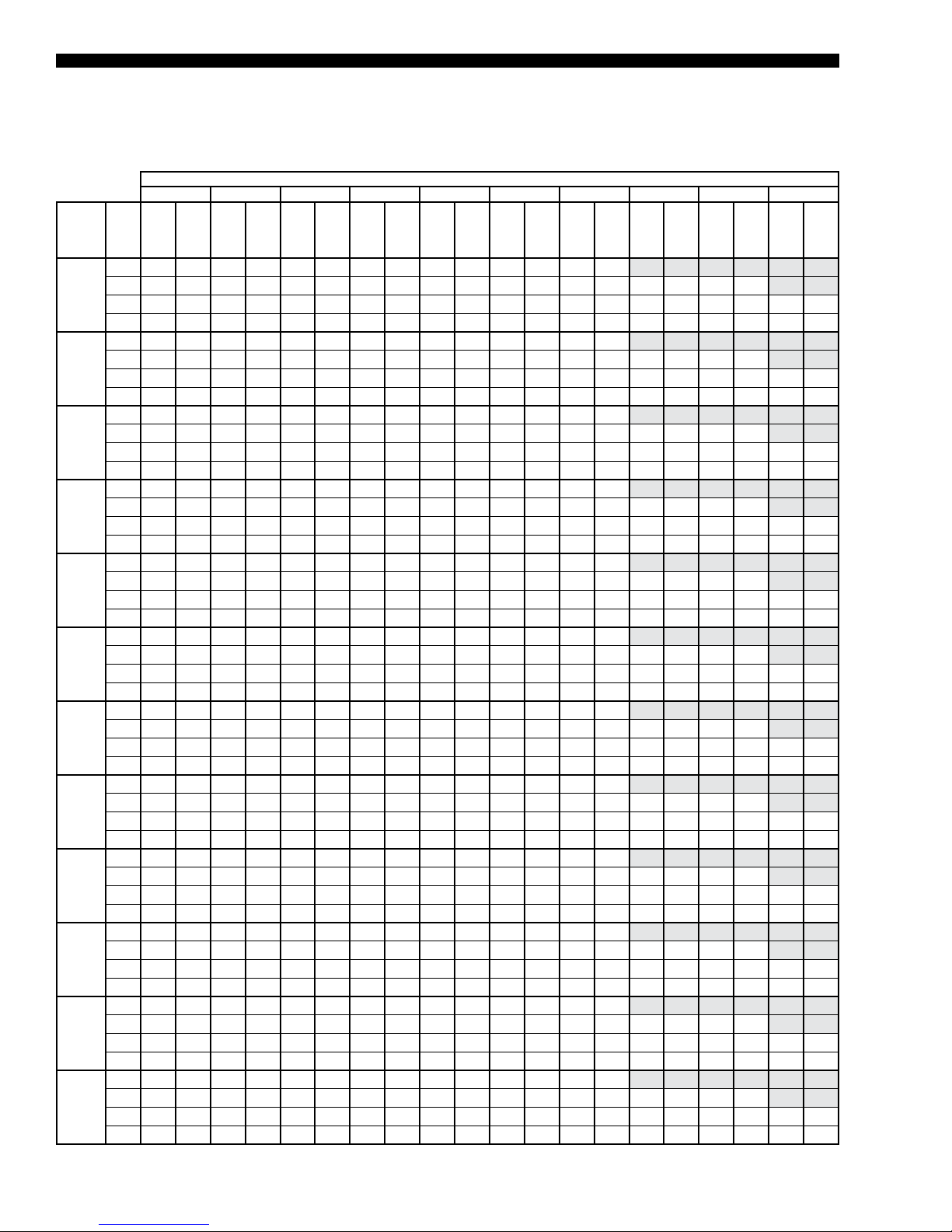
FORM100.50-EG12 (918)
Cooling Performance Data – 90 Ton Model (Cont’d)
TABLE 10 – COOLING PERFORMANCE DATA* – 90 TON MODEL (CONT’D)
95°F OUTDOOR AMBIENT TEMPERATURE
95°F 92°F 89°F 86°F 83°F 80°F 77°F 74°F 71°F 68°F
ENTERING AIR DRY BULB
CFM
17,500
19,250
21,000
22,750
24,500
26,250
28,000
29,750
31,500
33,250
35,000
36,000
* Rated performance is at sea level. Cooling capacities are gross cooling capacity.
TMBH
WB (°F)
75 1124 93 1122 93 1121 93 111 9 93 111 8 93 1117 93 111 7 93
71 1053 91 1052 91 1050 91 1049 91 1047 91 1046 91 1046 91 1046 91 1046 92
67 985 90 984 90 983 90 982 90 980 90 979 90 978 90 977 90 978 90 975 90
62 928 89 919 89 910 89 901 88 901 89 900 89 898 89 896 89 903 89 893 89
75 1145 93 1144 93 1142 93 1140 93 1139 93 1137 93 1138 94
71 1074 92 1073 92 1071 92 1070 92 1068 92 1066 92 1066 92 1066 92 1065 92
67 1006 90 1005 90 1004 90 1003 90 1001 91 999 91 998 91 997 91 998 91 994 91
62 962 89 949 89 935 89 922 89 920 89 919 89 917 89 915 89 926 89 912 89
75 1167 94 1165 94 1163 94 1161 94 1159 94 1158 94 1158 94
71 1095 92 1094 92 1092 92 1091 92 1089 92 1087 92 1839 92 1837 92 1085 92
67 1028 91 1026 91 1025 91 1023 91 1021 91 1020 91 1018 91 1017 91 1015 91 1014 91
62 996 90 978 90 960 90 942 89 940 89 939 89 937 89 935 89 933 89 930 89
75 1181 94 1179 94 1177 94 1175 94 1173 94 1171 94 1171 94
71 1109 93 1108 93 1107 93 1105 93 1103 93 1101 93 1664 93 1662 93 1098 93
67 1046 91 1043 91 1040 91 1037 91 1035 91 1034 91 1032 91 1030 91 1028 91 1026 91
62 1021 91 1000 90 980 90 959 90 956 90 953 90 950 90 948 90 946 90 944 90
75 1195 95 1193 95 1191 95 1189 95 1186 95 1184 95 1184 95
71 1124 93 1122 93 1121 93 111 9 93 111 7 93 1114 93 1489 93 1487 93 111 0 93
67 1064 92 1060 92 1056 92 1051 92 1049 92 1048 92 1045 92 1043 92 1041 92 1038 92
62 1047 91 1023 91 999 90 975 90 971 90 966 90 964 90 962 90 959 90 957 90
75 1209 95 1207 95 1205 95 1203 95 1200 95 1197 95 1196 95
71 1138 93 1137 93 1135 93 1134 93 1131 93 1128 93 1315 93 1312 93 1123 93
67 1083 92 1077 92 1071 92 1065 92 1064 92 1062 92 1059 92 1056 92 1053 92 1051 92
62 1072 92 1046 91 1019 91 992 90 986 90 980 90 978 90 975 90 973 90 970 90
75 1223 95 1221 95 1219 95 1216 95 1213 95 1210 95 1209 95
71 1153 94 1151 94 1149 94 1148 94 1145 94 1142 94 1140 94 1138 94 1135 94
67 1101 92 1094 92 1087 92 1079 92 1078 92 1076 92 1072 92 1069 92 1066 92 1063 92
62 1097 92 1068 92 1039 91 1009 91 1002 91 994 90 991 90 989 91 986 91 983 91
75 1232 96 1230 96 1227 96 1225 96 1222 96 1218 96 1217 96
71 1162 94 1160 94 1158 94 1156 94 1154 94 1151 94 1148 94 1146 94 1143 94
67 1118 93 1108 93 1098 92 1088 92 1086 92 1084 92 1081 92 1077 92 1074 92 1070 92
62 1115 93 1085 92 1055 91 1025 91 1014 91 1003 91 1000 91 997 91 994 91 991 91
75 1241 96 1239 96 1236 96 1234 96 1230 96 1226 96 1224 96
71 1172 94 1169 94 1167 94 1165 94 1162 94 1160 94 1157 94 1154 94 1151 94
67 1135 93 1123 93 1110 93 1097 93 1095 93 1093 93 1089 93 1085 93 1082 93 1078 93
62 1133 93 1102 92 1071 92 1040 91 1026 91 1011 91 1008 91 1005 91 1002 91 999 91
75 1250 96 1247 96 1245 96 1242 96 1238 96 1234 96 1232 96
71 1181 94 1179 94 1176 94 1174 94 1171 94 1168 94 1165 94 1162 94 1158 94
67 1153 94 1137 93 1121 93 1106 93 1103 93 1101 93 1097 93 1093 93 1089 93 1085 93
62 1151 94 111 9 93 1088 92 1056 92 1038 91 1020 91 1017 91 1014 91 1011 91 1008 91
75 1259 96 1256 96 1254 96 1251 96 1247 96 1243 96 1239 96
71 1191 95 1188 95 1185 95 1183 95 1180 95 1177 95 1173 95 1170 95 1166 95
67 1170 94 1151 94 1133 93 111 4 93 111 2 93 1110 93 1105 93 1101 93 1097 93 1093 93
62 1169 94 1137 93 1104 93 1071 92 1050 92 1028 91 1025 91 1022 91 1019 91 1016 91
75 1262 96 1260 96 1258 96 1255 96 1251 96 1246 96 1243 96
71 1197 95 1193 95 1190 95 1186 95 1182 95 1179 95 1176 95 1173 95 1170 95
67 1178 94 1158 94 1138 93 111 8 93 111 5 93 1113 93 1109 93 1105 93 1100 93 1096 93
62 1177 94 1144 94 1111 93 1078 92 1055 92 1032 91 1028 91 1024 91 1020 91 1017 91
SMBH
TMBH
SMBH
TMBH
SMBH
TMBH
SMBH
TMBH
SMBH
TMBH
SMBH
TMBH
SMBH
TMBH
SMBH
TMBH
SMBH
TMBH
SMBH
42
JOHNSON CONTROLS
Page 43

TABLE 10 – COOLING PERFORMANCE DATA* – 90 TON MODEL (CONT’D)
105°F OUTDOOR AMBIENT TEMPERATURE
ENTERING AIR DRY BULB
95°F 92°F 89°F 86°F 83°F 80°F 77°F 74°F 71°F 68°F
FORM 100.50-EG12 (918)
CFM
75 1075 102 1073 102 1071 102 1070 102 1069 102 1067 103 1068 103
17,500
19,250
21,000
22,750
24,500
26,250
28,000
29,750
31,500
33,250
35,000
36,000
* Rated performance is at sea level. Cooling capacities are gross cooling capacity.
71 1007 101 1006 101 1004 101 1003 101 1001 101 1000 101 999 100 998 99 997 98
67 934 100 936 100 937 100 939 100 937 100 935 100 934 100 933 100 933 100 931 100
62 897 98 885 98 873 98 861 98 861 98 860 98 858 98 856 98 858 98 852 98
75 1094 103 1092 103 1091 103 1089 103 1087 103 1086 103 1086 103
71 1026 102 1025 101 1024 101 1022 101 1020 101 1018 101 1017 101 1016 100 1015 100
67 958 100 958 100 958 100 958 100 956 100 954 100 953 100 951 100 952 100 948 100
62 929 99 913 99 897 99 881 98 879 98 878 98 876 98 874 98 886 99 870 99
75 1114 103 1112 103 1110 103 1108 103 1106 103 1104 103 1104 103
71 1045 102 1044 102 1043 102 1041 102 1039 102 1037 102 1412 102 1411 102 1034 102
67 983 100 981 100 979 100 977 100 975 100 973 100 971 100 969 100 968 101 966 101
62 961 100 941 99 920 99 900 99 898 99 896 99 893 99 891 99 889 99 887 99
75 1127 104 1125 104 1123 104 1121 104 1119 104 111 6 104 1116 104
71 1059 102 1058 102 1056 102 1055 102 1052 102 1050 102 1331 102 1329 102 1046 102
67 1002 101 998 101 994 101 990 101 988 101 986 101 984 101 982 101 980 101 977 101
62 985 100 963 100 940 99 917 99 913 99 909 99 906 99 904 99 902 99 899 99
75 1141 104 1139 104 1136 104 1134 104 1132 104 1129 104 1128 104
71 1073 102 1071 102 1070 102 1068 102 1066 102 1063 102 1250 102 1248 102 1058 102
67 1021 101 1015 101 1009 101 1003 101 1001 101 1000 101 997 101 994 101 992 101 989 101
62 1009 101 985 100 960 100 935 99 928 99 922 99 919 99 917 99 914 99 912 99
75 1154 104 1152 104 1150 104 1147 104 1144 104 1141 104 1140 104
71 1086 102 1085 102 1083 102 1082 102 1079 102 1077 102 1169 102 1166 102 1070 102
67 1040 101 1032 101 1024 101 1017 101 1015 101 1013 101 1010 101 1007 101 1004 101 1001 101
62 1034 101 1007 100 979 100 952 99 944 99 935 99 932 99 930 99 927 99 924 99
75 1168 104 1165 104 1163 104 1161 104 1157 104 1154 104 1152 104
71 1100 102 1098 102 1097 102 1095 103 1092 103 1090 103 1087 103 1085 103 1082 103
67 1059 101 1049 101 1040 101 1030 101 1028 101 1026 101 1023 101 1019 101 1016 101 1013 101
62 1058 101 1029 101 999 100 970 99 959 99 948 99 945 99 942 99 940 99 937 99
75 1175 104 1173 104 1170 104 1168 105 1164 105 1160 105 1158 105
71 1109 103 1107 103 1105 103 1102 103 1100 103 1097 103 1094 103 1091 103 1088 103
67 1075 102 1062 102 1050 101 1037 101 1035 101 1033 101 1030 101 1026 101 1022 101 1019 102
62 1074 102 1044 101 1014 101 984 100 970 100 956 100 953 100 950 100 947 100 944 100
75 1183 105 1180 105 1178 105 1175 105 1171 105 1167 105 1164 105
71 1118 103 1115 103 1113 103 1110 103 1107 103 1104 103 1101 103 1098 103 1094 103
67 1091 102 1076 102 1060 102 1045 102 1043 102 1040 102 1036 102 1032 102 1028 102 1024 102
62 1091 102 1060 102 1029 101 999 100 981 100 964 100 960 100 957 100 954 100 950 100
75 1190 105 1188 105 1185 105 1183 105 1178 105 1174 105 1171 105
71 1127 103 1124 103 1120 104 1117 104 1114 104 1111 104 1108 104 1104 104 1100 104
67 1108 103 1089 103 1071 102 1052 102 1050 102 1048 102 1043 102 1039 102 1035 102 1030 102
62 1107 103 1076 102 1044 102 1013 101 992 101 971 100 968 100 964 100 961 100 957 100
75 1198 105 1195 105 1192 106 1190 106 1185 106 1181 106 1177 106
71 1136 104 1132 104 1128 104 1124 104 1121 104 111 8 104 1114 104 1110 104 1106 104
67 1124 103 1102 103 1081 103 1060 102 1057 102 1055 102 1050 102 1046 102 1041 102 1036 102
62 1123 103 1091 103 1060 102 1028 101 1003 101 979 100 975 101 972 101 968 101 964 101
75 1201 106 1198 106 1196 106 1193 106 1189 106 1184 106 1180 106
71 1143 104 1138 104 1133 104 1128 104 1124 104 1120 104 111 7 104 1113 104 1109 104
67 1131 104 1109 103 1086 103 1063 102 1061 102 1058 103 1053 103 1049 103 1044 103 1039 103
62 1131 104 1099 103 1066 102 1034 102 1009 101 983 101 979 101 974 101 970 101 965 101
WB (°F)
TMBH
SMBH
TMBH
SMBH
TMBH
SMBH
TMBH
SMBH
TMBH
SMBH
TMBH
SMBH
TMBH
SMBH
TMBH
SMBH
TMBH
SMBH
TMBH
SMBH
JOHNSON CONTROLS
43
Page 44

FORM100.50-EG12 (918)
Cooling Performance Data – 90 Ton Model (Cont’d)
TABLE 10 – COOLING PERFORMANCE DATA* – 90 TON MODEL (CONT’D)
115°F OUTDOOR AMBIENT TEMPERATURE
95°F 92°F 89°F 86°F 83°F 80°F 77°F 74°F 71°F 68°F
ENTERING AIR DRY BULB
CFM
17,500
19,250
21,000
22,750
24,500
26,250
28,000
29,750
31,500
33,250
35,000
36,000
* Rated performance is at sea level. Cooling capacities are gross cooling capacity.
TMBH
WB (°F)
75 1025 11 2 1024 112 1022 112 1020 11 2 1019 112 1017 112 1018 112
71 962 111 960 111 959 111 957 110 955 11 0 953 11 0 951 108 950 106 948 104
67 883 11 0 887 109 891 109 895 109 894 109 892 109 891 109 889 109 888 109 887 109
62 865 108 851 108 836 107 821 107 820 107 820 107 818 107 816 107 814 108 812 108
75 1043 11 2 1041 112 1040 112 1038 11 2 1036 112 1034 112 1034 113
71 979 111 977 111 976 111 974 111 972 111 970 111 969 11 0 967 109 966 108
67 910 11 0 911 11 0 912 109 913 109 911 109 909 109 908 109 906 110 906 11 0 902 110
62 895 109 877 108 858 108 840 108 838 108 836 108 834 108 832 108 847 108 827 108
75 1061 11 3 1059 113 1057 113 1055 11 3 1053 113 1050 113 1050 113
71 996 111 995 111 993 111 992 111 989 111 987 111 986 111 984 111 983 111
67 938 11 0 935 11 0 933 110 930 11 0 928 110 927 110 925 11 0 922 110 920 110 918 11 0
62 925 109 903 109 881 108 858 108 855 108 853 108 850 108 848 108 845 108 843 108
75 1073 11 3 1071 113 1068 113 1066 11 3 1064 113 1061 113 1060 113
71 1008 111 1006 111 1005 111 1003 112 1001 11 2 998 11 2 997 112 995 11 2 993 11 2
67 957 11 0 952 11 0 947 110 942 11 0 940 110 938 110 935 11 0 933 110 930 110 928 11 0
62 948 11 0 924 109 900 109 876 108 870 108 864 108 861 108 859 109 856 109 854 109
75 1084 11 3 1082 113 1080 113 1078 11 3 1074 114 1071 114 1070 114
71 1020 11 2 1018 112 1016 112 1014 11 2 1012 112 1009 112 1007 112 1005 112 1003 112
67 976 111 969 11 0 961 110 953 110 951 11 0 949 110 946 110 943 111 940 111 937 111
62 970 11 0 944 11 0 919 109 893 109 884 109 875 109 873 109 870 109 867 109 865 109
75 1096 11 4 1094 114 1091 114 1089 11 4 1085 114 1082 114 1080 114
71 1031 11 2 1030 112 1028 112 1026 11 2 1023 112 1021 112 1018 112 1016 112 1013 112
67 996 111 985 111 975 111 964 111 962 111 961 111 957 111 954 111 950 111 947 111
62 992 111 965 11 0 938 110 9 11 109 899 109 887 109 884 109 881 109 878 109 875 109
75 1108 11 4 1105 114 1103 114 1100 114 1096 114 1092 114 1090 114
71 1043 11 2 1041 112 1039 112 1037 11 2 1035 112 1032 113 1029 113 1026 113 1023 113
67 1015 111 1002 111 989 111 976 111 974 111 972 111 968 111 964 111 961 111 957 111
62 1014 111 986 111 957 11 0 928 110 913 109 898 109 895 109 892 109 889 109 886 109
75 1115 114 1112 114 1110 114 1107 114 1103 11 4 1099 114 1096 114
71 1053 11 2 1050 113 1047 113 1044 11 3 1042 113 1039 113 1036 113 1033 113 1029 113
67 1031 11 2 1015 112 999 111 983 111 981 111 979 111 975 111 971 111 967 111 963 111
62 1030 11 2 1001 111 971 111 942 11 0 924 11 0 906 109 903 109 899 109 896 11 0 893 110
75 1122 11 4 1120 114 1117 114 1114 114 1110 115 1105 115 1102 115
71 1063 11 3 1059 113 1055 113 1052 11 3 1049 113 1046 113 1042 113 1039 113 1035 113
67 1046 11 2 1028 112 1009 112 990 111 988 111 986 111 982 111 977 111 973 11 2 968 112
62 1046 11 2 1016 112 986 111 956 11 0 935 110 914 109 910 11 0 907 110 903 110 899 11 0
75 1129 11 5 1127 115 1124 115 1121 115 1117 115 1112 115 1108 115
71 1072 11 3 1068 113 1063 113 1059 11 3 1056 113 1053 113 1049 113 1045 113 1041 113
67 1062 11 3 1041 112 1019 112 998 111 995 111 993 111 988 112 984 11 2 979 11 2 974 112
62 1061 11 3 1031 112 1001 111 970 111 946 11 0 922 110 918 11 0 914 110 910 110 906 11 0
75 1137 11 5 1134 115 1131 115 1129 115 1124 115 1118 115 1114 115
71 1082 11 3 1077 113 1071 113 1066 11 3 1063 113 1059 113 1055 113 1051 113 1047 113
67 1078 11 3 1053 113 1029 112 1005 11 2 1003 112 1000 112 995 11 2 990 112 985 112 980 11 2
62 1077 11 3 1046 112 1015 112 984 111 957 11 0 930 110 925 11 0 921 110 917 110 913 11 0
75 1140 11 5 1137 115 1134 115 1132 115 1127 115 1121 115 1116 115
71 1090 11 3 1083 113 1076 113 1069 11 3 1066 113 1062 113 1058 114 1053 114 1049 114
67 1085 11 3 1060 113 1034 112 1009 11 2 1006 112 1003 112 998 11 2 993 112 987 112 982 11 2
62 1085 11 3 1053 113 1022 112 990 111 962 111 935 111 929 111 924 111 919 11 0 914 110
SMBH
TMBH
SMBH
TMBH
SMBH
TMBH
SMBH
TMBH
SMBH
TMBH
SMBH
TMBH
SMBH
TMBH
SMBH
TMBH
SMBH
TMBH
SMBH
44
JOHNSON CONTROLS
Page 45
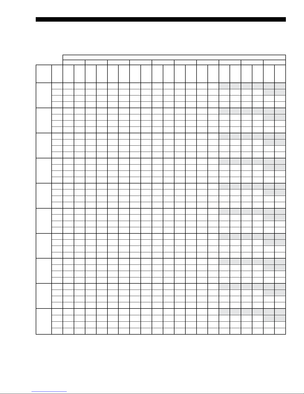
Cooling Performance Data – 105 Ton Model
TABLE 11 - COOLING PERFORMANCE DATA* – 105 TON MODEL
75°F OUTDOOR AMBIENT TEMPERATURE
ENTERING AIR DRY BULB
95°F 92°F 89°F 86°F 83°F 80°F 77°F 74°F 71°F 68°F
FORM 100.50-EG12 (918)
CFM
75 1462 95 1461 95 1460 95 1460 95 1460 95 1460 95 1460 95
21,000
22,750
24,500
26,250
28,000
29,750
31,500
33,250
35,000
36,000
* Rated performance is at sea level. Cooling capacities are gross cooling capacity.
71 1364 93 1363 93 1363 93 1362 93 1361 93 1361 93 1361 93 1361 93 1362 93
67 1273 91 1272 91 1272 91 1272 91 1271 91 1271 90 1270 90 1270 90 1269 90 1269 90
62 1190 89 1182 89 1174 88 1166 88 1166 88 1165 88 1165 88 1166 88 1166 88 1166 89
75 1487 95 1486 95 1485 95 1484 95 1484 95 1484 95 1485 95
71 1388 93 1388 93 1387 93 1386 93 1386 93 1385 93 1385 93 1385 93 1386 93
67 1297 91 1296 91 1296 91 1295 91 1295 91 1294 91 1294 91 1293 91 1293 91 1292 91
62 1227 90 1214 89 1201 89 1188 89 1188 89 1187 89 1187 89 1187 89 1187 89 1187 89
75 1512 96 1511 96 1510 96 1509 96 1509 96 1508 96 1509 96
71 1413 94 1412 94 1412 94 1411 94 1410 94 1409 94 1409 94 1409 94 1409 94
67 1321 92 1320 92 1320 92 1319 92 1318 92 1318 92 1317 92 1317 92 1316 92 1316 91
62 1265 90 1247 90 1229 90 1211 89 1210 89 1209 89 1209 89 1209 89 1208 89 1208 89
75 1537 97 1536 97 1535 97 1534 97 1533 97 1533 97 1533 97
71 1437 94 1437 94 1436 94 1435 94 1434 94 1434 94 1433 94 1433 94 1433 94
67 1345 92 1344 92 1343 92 1343 92 1342 92 1341 92 1340 92 1340 92 1339 92 1339 92
62 1303 91 1279 91 1256 90 1233 90 1232 90 1231 90 1231 90 1230 90 1229 90 1229 90
75 1562 97 1560 97 1559 97 1558 97 1558 97 1557 97 1558 97
71 1462 95 1461 95 1460 95 1459 95 1459 95 1458 95 1458 95 1457 95 1457 95
67 1369 93 1368 93 1367 93 1366 93 1365 93 1364 93 1364 93 1363 93 1363 93 1362 93
62 1340 92 1312 91 1283 91 1255 90 1254 90 1253 90 1252 90 1251 90 1251 90 1250 90
75 1578 98 1576 98 1575 98 1574 98 1573 98 1572 98 1573 98
71 1478 95 1477 95 1476 95 1475 95 1474 95 1473 95 1473 95 1472 95 1472 95
67 1391 93 1388 93 1384 93 1381 93 1380 93 1379 93 1375 93 1371 93 1366 93 1362 93
62 1368 93 1337 92 1305 91 1274 91 1271 90 1268 90 1264 90 1259 90 1254 90 1250 90
75 1594 98 1592 98 1591 98 1590 98 1589 98 1588 98 1588 98
71 1494 96 1493 96 1492 96 1491 96 1490 96 1488 96 1488 96 1488 95 1487 95
67 1412 94 1407 94 1401 93 1396 93 1395 93 1394 93 1386 93 1378 93 1370 93 1362 93
62 1397 93 1362 93 1328 92 1293 91 1288 91 1283 91 1275 91 1267 90 1258 90 1250 90
75 1609 99 1608 99 1607 98 1606 98 1604 98 1603 98 1604 98
71 1510 96 1509 96 1508 96 1507 96 1505 96 1504 96 1503 96 1503 96 1502 96
67 1433 94 1426 94 1419 94 1411 94 1410 94 1409 94 1397 93 1386 93 1374 93 1362 93
62 1425 94 1387 93 1350 92 1312 91 1305 91 1298 91 1286 91 1274 91 1262 90 1250 90
75 1625 99 1624 99 1623 99 1621 99 1620 99 1618 99 1619 99
71 1526 96 1525 96 1523 96 1522 96 1521 96 1519 96 1518 96 1518 96 1517 96
67 1454 95 1445 94 1436 94 1426 94 1425 94 1424 94 1408 94 1393 93 1378 93 1362 93
62 1453 95 1413 94 1372 93 1332 92 1323 92 1313 91 1298 91 1282 91 1266 90 1250 90
75
71
67
62
WB (°F)
TMBH
SMBH
TMBH
SMBH
TMBH
SMBH
TMBH
SMBH
TMBH
SMBH
1635 99 1633 99 1632 99 1630 99 1629 99 1627 99 1627 99
1535 97 1534 97 1532 97 1531 97 1529 96 1528 96 1527 96 1527 96 1526 96
1466 95 1456 95 1445 94 1435 94 1434 94 1432 94 1415 94 1397 93 1380 93 1362 93
1469 95 1427 94 1385 93 1343 92 1332 92 1322 92 1304 91 1286 91 1268 90 1250 90
TMBH
SMBH
TMBH
SMBH
TMBH
TMBH
SMBH
SMBH
TMBH
SMBH
JOHNSON CONTROLS
45
Page 46

FORM100.50-EG12 (918)
Cooling Performance Data – 105 Ton Model (Cont’d)
TABLE 11 – COOLING PERFORMANCE DATA* – 105 TON MODEL (CONT’D)
85°F OUTDOOR AMBIENT TEMPERATURE
95°F 92°F 89°F 86°F 83°F 80°F 77°F 74°F 71°F 68°F
ENTERING AIR DRY BULB
CFM
21,000
22,750
24,500
26,250
28,000
29,750
31,500
33,250
35,000
36,000
* Rated performance is at sea level. Cooling capacities are gross cooling capacity.
TMBH
WB (°F)
75 1409 104 1408 104 1407 104 1407 104 1407 104 1406 104 1407 104
71 1315 102 1314 102 1314 102 1313 102 1312 102 1312 102 1312 102 1312 102 1313 102
67 1226 100 1226 100 1226 100 1226 100 1225 100 1225 100 1224 100 1224 100 1224 100 1223 100
62 1157 98 1146 98 1135 98 1124 97 1124 97 1124 97 1123 97 1123 97 1123 97 1122 97
75 1432 104 1432 104 1431 104 1430 104 1430 104 1429 104 1430 104
71 1338 102 1337 102 1337 102 1336 102 1335 102 1335 102 1335 102 1335 102 1335 102
67 1250 100 1249 100 1249 100 1248 100 1248 100 1247 100 1247 100 1246 100 1246 100 1245 100
62 1193 99 1177 98 1161 98 1145 98 1145 98 1144 98 1144 98 1143 98 1143 98 1143 98
75 1456 105 1455 105 1454 105 1454 105 1453 105 1452 105 1453 105
71 1362 103 1361 103 1360 103 1359 102 1358 102 1358 102 1358 102 1358 102 1358 102
67 1273 100 1272 100 1271 100 1271 100 1270 100 1269 100 1269 100 1268 100 1268 100 1267 100
62 1229 99 1208 99 1187 98 1166 98 1166 98 1165 98 1165 98 1164 98 1163 98 1163 98
75 1480 105 1479 105 1478 105 1477 105 1476 105 1475 105 1476 105
71 1385 103 1384 103 1383 103 1382 103 1381 103 1380 103 1380 103 1380 103 1380 103
67 1296 101 1295 101 1294 101 1293 101 1292 101 1291 101 1291 101 1290 101 1290 101 1289 101
62 1265 100 1239 99 1213 99 1187 98 1187 98 1186 98 1185 98 1184 98 1184 98 1183 98
75 1503 106 1502 106 1501 106 1501 106 1499 106 1498 106 1499 106
71 1408 103 1407 103 1406 103 1405 103 1404 103 1403 103 1403 103 1403 103 1403 103
67 1319 101 1318 101 1317 101 1316 101 1315 101 1314 101 1313 101 1313 101 1312 101 1312 101
62 1302 101 1271 100 1239 99 1208 99 1208 99 1207 99 1206 99 1205 98 1204 98 1203 98
75 1517 106 1516 106 1515 106 1514 106 1513 106 1512 106 1512 106
71 1422 104 1421 104 1420 104 1419 104 1418 104 1417 104 1417 104 1416 104 1416 104
67 1341 102 1337 102 1333 102 1329 102 1328 102 1326 102 1324 101 1322 101 1319 101 1317 101
62 1328 102 1295 101 1262 100 1228 99 1224 99 1220 99 1217 99 1215 99 1212 99 1209 99
75 1531 107 1530 107 1529 107 1528 107 1527 107 1525 107 1526 107
71 1436 104 1435 104 1434 104 1433 104 1432 104 1431 104 1430 104 1430 104 1429 104
67 1364 103 1356 102 1349 102 1342 102 1341 102 1339 102 1335 102 1331 102 1327 102 1323 102
62 1355 102 1319 102 1284 101 1249 100 1241 100 1234 99 1229 99 1224 99 1220 99 1215 99
75 1545 107 1544 107 1543 107 1542 107 1540 107 1539 107 1539 107
71 1451 105 1449 105 1448 105 1447 105 1446 105 1444 105 1444 105 1443 105 1442 105
67 1386 103 1376 103 1366 103 1356 103 1354 103 1352 102 1346 102 1340 102 1334 102 1328 102
62 1381 103 1344 102 1306 101 1269 100 1258 100 1247 100 1241 100 1234 100 1227 99 1221 99
75 1560 108 1558 108 1557 108 1555 108 1554 108 1552 108 1552 108
71 1465 105 1463 105 1462 105 1461 105 1459 105 1458 105 1457 105 1456 105 1456 105
67 1409 104 1395 104 1382 103 1369 103 1367 103 1365 103 1357 103 1349 103 1341 102 1334 102
62 1408 104 1368 103 1328 102 1289 101 1275 101 1261 100 1252 100 1244 100 1235 100 1226 100
75
1568 108 1566 108 1565 108 1564 108 1562 108 1560 108 1560 108
71
1473 106 1472 106 1471 106 1469 106 1468 106 1466 106 1465 105 1464 105 1464 105
67
1422 104 1407 104 1392 104 1377 103 1375 103 1372 103 1364 103 1355 103 1346 103 1337 102
62
1423 104 1382 103 1341 102 1300 101 1285 101 1269 101 1259 100 1249 100 1240 100 1230 100
SMBH
TMBH
SMBH
TMBH
SMBH
TMBH
SMBH
TMBH
SMBH
TMBH
SMBH
TMBH
SMBH
TMBH
SMBH
TMBH
SMBH
TMBH
SMBH
46
JOHNSON CONTROLS
Page 47

TABLE 11 – COOLING PERFORMANCE DATA* – 105 TON MODEL (CONT’D)
95°F OUTDOOR AMBIENT TEMPERATURE
ENTERING AIR DRY BULB
95°F 92°F 89°F 86°F 83°F 80°F 77°F 74°F 71°F 68°F
FORM 100.50-EG12 (918)
CFM
75 1356 11 3 1355 113 1354 113 1354 11 3 1353 113 1353 113 1354 113
21,000
22,750
24,500
26,250
28,000
29,750
31,500
33,250
35,000
36,000
* Rated performance is at sea level. Cooling capacities are gross cooling capacity.
71 1266 111 1265 111 1265 111 1264 111 1263 111 1263 111 1263 111 1263 111 1264 111
67 1180 109 1180 109 1180 109 1180 109 1179 109 1179 109 1178 109 1178 109 1178 109 1178 109
62 1123 107 1110 107 1096 107 1082 106 1082 106 1082 106 1081 106 1080 106 1080 106 1079 106
75 1377 11 4 1376 114 1375 114 1375 11 4 1374 114 1374 114 1374 114
71 1287 111 1286 111 1285 111 1285 111 1284 111 1283 111 1283 111 1284 111 1284 111
67 1202 109 1201 109 1201 109 1200 109 1200 109 1199 109 1199 109 1198 109 1198 109 1197 109
62 1158 108 1139 108 1120 107 1101 107 1101 107 1101 107 1100 107 1099 107 1098 107 1097 107
75 1398 11 4 1397 114 1396 114 1395 11 4 1395 114 1394 114 1395 114
71 1308 11 2 1307 112 1306 112 1305 11 2 1305 112 1304 112 1304 112 1304 112 1304 112
67 1223 11 0 1222 110 1221 110 1220 11 0 1220 110 1219 110 1219 110 1218 110 1218 110 1217 110
62 1192 109 1168 108 1145 108 1121 107 1120 107 111 9 107 1119 107 1118 107 1117 107 1116 107
75 1419 11 5 1418 115 1417 115 1416 11 5 1415 115 1414 115 1415 115
71 1329 11 3 1328 112 1327 112 1326 11 2 1325 112 1324 112 1324 112 1324 112 1324 112
67 1245 11 0 1243 110 1242 110 1241 11 0 1240 110 1239 110 1239 110 1238 110 1238 110 1237 110
62 1226 11 0 1198 109 1169 108 1141 108 1139 108 1138 108 1137 108 1136 108 1135 108 1134 108
75 1440 11 6 1439 116 1438 116 1437 11 6 1436 115 1435 115 1436 115
71 1350 11 3 1349 113 1348 113 1347 11 3 1346 113 1345 113 1344 113 1344 112 1344 112
67 1266 111 1264 111 1263 111 1261 111 1260 111 1260 111 1259 111 1258 111 1257 111 1257 111
62 1260 111 1227 110 1194 109 1160 108 1159 108 1157 108 1156 108 1155 108 1154 108 1153 108
75 1453 11 6 1452 116 1451 116 1450 11 6 1449 116 1448 116 1448 116
71 1363 11 3 1362 113 1361 113 1360 11 3 1359 113 1358 113 1357 113 1357 113 1356 113
67 1290 11 2 1285 111 1279 111 1274 111 1272 111 1271 111 1271 111 1270 111 1269 111 1269 111
62 1286 111 1251 111 1216 11 0 1182 109 1176 109 1170 108 1169 108 1168 108 1167 108 1166 108
75 1467 11 6 1466 116 1464 116 1463 11 6 1462 116 1460 116 1461 116
71 1377 11 4 1375 114 1374 114 1373 11 4 1372 114 1371 114 1370 113 1369 113 1369 113
67 1315 11 2 1305 112 1296 112 1286 111 1285 111 1283 111 1282 111 1282 111 1281 111 1281 112
62 1311 11 2 1275 111 1239 110 1203 109 1193 109 1183 109 1181 109 1180 109 1179 109 1178 109
75 1480 11 7 1479 117 1478 117 1476 11 7 1475 117 1473 117 1474 117
71 1390 11 4 1389 114 1388 114 1387 11 4 1385 114 1384 114 1383 114 1382 114 1381 114
67 1339 11 3 1326 112 1312 112 1299 11 2 1297 112 1294 112 1294 112 1294 112 1293 112 1293 112
62 1337 11 3 1299 112 1262 111 1225 11 0 1210 109 1195 109 1194 109 1193 109 1192 109 1191 109
75 1494 11 7 1492 117 1491 117 1489 11 7 1488 117 1486 117 1486 117
71 1403 11 5 1402 114 1401 114 1400 11 4 1398 114 1396 114 1396 114 1395 114 1394 114
67 1363 11 3 1346 113 1329 112 1312 11 2 1309 112 1306 112 1306 112 1305 112 1305 112 1305 112
62 1362 11 3 1323 112 1285 111 1246 11 0 1227 110 1208 109 1207 109 1206 109 1204 109 1203 109
75
71
67
62
WB (°F)
TMBH
SMBH
TMBH
SMBH
TMBH
SMBH
TMBH
SMBH
TMBH
SMBH
1501 117 1500 117 1498 117 1497 117 1495 117 1493 117 1493 117
1411 115 1410 115 1409 115 1407 115 1406 115 1404 115 1403 114 1402 114 1401 114
1377 114 1358 113 1339 113 1319 112 1316 112 1313 112 1312 112 1312 112 1312 112 1312 112
1376 114 1337 113 1298 112 1258 111 1237 110 1216 110 1214 109 1213 109 1212 109 1210 109
TMBH
SMBH
TMBH
SMBH
TMBH
SMBH
TMBH
SMBH
TMBH
SMBH
JOHNSON CONTROLS
47
Page 48

FORM100.50-EG12 (918)
Cooling Performance Data – 105 Ton Model (Cont’d)
TABLE 11 – COOLING PERFORMANCE DATA* – 105 TON MODEL (CONT’D)
105°F OUTDOOR AMBIENT TEMPERATURE
95°F 92°F 89°F 86°F 83°F 80°F 77°F 74°F 71°F 68°F
ENTERING AIR DRY BULB
CFM
21,000
22,750
24,500
26,250
28,000
29,750
31,500
33,250
35,000
36,000
* Rated performance is at sea level. Cooling capacities are gross cooling capacity.
TMBH
WB (°F)
75 1294 125 1293 125 1292 125 1292 125 1291 125 1291 125 1292 125
71 1208 123 1208 123 1207 123 1207 123 1206 123 1205 123 1206 123 1206 123 1206 123
67 1127 120 1127 120 1126 120 1126 120 1126 120 1125 120 1125 120 1125 120 1124 120 1124 120
62 1084 11 9 1067 119 1049 118 1032 11 8 1032 118 1032 118 1032 118 1031 118 1030 118 1030 118
75 1314 125 1313 125 1312 125 1311 125 1311 125 1310 125 1311 125
71 1228 123 1227 123 1227 123 1226 123 1225 123 1224 123 1224 123 1225 123 1225 123
67 1149 121 1148 121 1147 121 1145 121 1145 121 1144 121 1144 121 1143 121 1143 121 1143 121
62 1117 120 1095 119 1074 11 9 1052 118 1051 118 1050 11 8 1050 118 1049 118 1049 11 8 1048 118
75 1333 126 1332 126 1331 126 1331 126 1330 126 1329 126 1330 126
71 1248 123 1247 123 1246 123 1245 123 1244 123 1243 123 1243 123 1243 123 1244 123
67 1171 121 1169 121 1167 121 1165 121 1164 121 1163 121 1163 121 1162 121 1162 121 1161 121
62 1150 121 1124 120 1098 119 1073 119 1070 119 1068 11 8 1067 11 8 1067 119 1067 119 1066 119
75 1353 126 1352 126 1351 126 1350 126 1349 126 1349 126 1349 126
71 1267 124 1266 124 1265 124 1265 124 1263 124 1262 124 1262 124 1262 124 1262 124
67 1194 122 1190 122 1187 121 1184 121 1183 121 1182 121 1182 121 1181 121 1180 121 1180 121
62 1182 121 1153 121 1123 120 1093 119 1089 119 1086 119 1085 11 9 1085 119 1085 119 1085 11 9
75 1373 127 1372 127 1371 127 1369 127 1369 127 1368 127 1368 127
71 1287 124 1286 124 1285 124 1284 124 1282 124 1281 124 1281 124 1281 124 1281 124
67 1216 122 1212 122 1207 122 1203 122 1202 122 1201 122 1200 122 1200 122 1199 122 1198 122
62 1215 122 1181 121 1147 120 1113 119 1108 119 1103 11 9 1103 119 1103 119 1103 11 9 1103 119
75 1384 127 1383 127 1382 127 1381 127 1380 127 1378 127 1379 127
71 1299 125 1298 125 1296 125 1295 125 1294 124 1293 124 1292 124 1292 124 1292 124
67 1239 123 1231 123 1222 122 1214 122 1213 122 1211 122 1211 122 1210 122 1209 122 1208 122
62 1238 123 1204 122 1169 121 1134 120 1124 120 111 4 11 9 1114 120 111 3 120 1113 120 1113 120
75 1396 128 1395 128 1393 128 1392 128 1391 128 1389 128 1390 128
71 1310 125 1309 125 1308 125 1307 125 1305 125 1304 125 1303 125 1303 125 1302 125
67 1263 124 1250 123 1238 123 1225 123 1223 123 1222 123 1221 123 1220 123 1219 123 1218 122
62 1262 124 1226 123 1190 122 1154 121 1140 120 1125 120 1125 120 1124 120 1123 120 1123 120
75 1408 128 1406 128 1405 128 1404 128 1402 128 1400 128 1400 128
71 1322 126 1321 126 1320 126 1318 126 1317 126 1315 125 1315 125 1314 125 1313 125
67 1286 125 1269 124 1253 124 1236 123 1234 123 1232 123 1231 123 1230 123 1229 123 1228 123
62 1285 125 1249 124 1212 123 1175 122 1156 121 1136 120 1135 120 1134 120 1134 120 1133 120
75 1419 129 1418 129 1416 129 1415 129 1413 129 1411 129 1411 129
71 1334 126 1332 126 1331 126 1330 126 1328 126 1327 126 1326 126 1325 126 1324 126
67 1309 126 1289 125 1268 124 1247 124 1245 124 1243 124 1241 124 1240 123 1239 123 1238 123
62 1309 126 1271 124 1233 123 1196 122 1172 122 1147 121 1146 121 1145 121 1144 121 1143 121
75
1426 129 1425 129 1423 129 1422 129 1420 129 1418 129 1418 129
71
1341 126 1339 126 1338 126 1337 126 1335 126 1333 126 1332 126 1331 126 1330 126
67
1323 126 1300 125 1277 125 1254 124 1251 124 1249 124 1247 124 1246 124 1244 124 1243 123
62
1322 126 1284 125 1246 124 1207 123 1181 122 1154 121 1153 121 1151 121 1150 121 1149 121
SMBH
TMBH
SMBH
TMBH
SMBH
TMBH
SMBH
TMBH
SMBH
TMBH
SMBH
TMBH
SMBH
TMBH
SMBH
TMBH
SMBH
TMBH
SMBH
48
JOHNSON CONTROLS
Page 49

TABLE 11 – COOLING PERFORMANCE DATA* – 105 TON MODEL (CONT’D)
115°F OUTDOOR AMBIENT TEMPERATURE
ENTERING AIR DRY BULB
95°F 92°F 89°F 86°F 83°F 80°F 77°F 74°F 71°F 68°F
FORM 100.50-EG12 (918)
CFM
75 1233 137 1231 137 1230 137 1229 137 1229 137 1230 137 1230 137
21,000
22,750
24,500
26,250
28,000
29,750
31,500
33,250
35,000
36,000
* Rated performance is at sea level. Cooling capacities are gross cooling capacity.
71 1150 134 1150 134 1150 134 1149 134 1148 134 1148 134 1148 134 1148 134 1149 134
67 1073 132 1073 132 1073 132 1072 132 1072 132 1072 132 1072 132 1071 132 1071 132 1070 132
62 1045 131 1024 131 1003 130 982 130 983 130 983 130 982 129 982 129 981 129 981 129
75 1250 137 1249 137 1248 137 1247 137 1246 137 1246 137 1246 137
71 1168 135 1167 135 1167 135 1166 135 1165 135 1164 135 1164 135 1165 135 1165 135
67 1096 133 1094 133 1092 133 1089 133 1089 133 1089 133 1089 133 1090 133 1090 133 1091 132
62 1075 132 1051 131 1027 131 1003 130 1001 130 999 130 998 130 997 130 997 130 996 130
75 1267 138 1266 138 1265 138 1264 138 1263 138 1262 138 1263 138
71 1185 135 1185 135 1184 135 1183 135 1182 135 1181 135 1181 135 1181 135 1181 135
67 1120 133 1115 133 1111 133 1106 133 1106 133 1105 133 1107 133 1108 133 1110 133 111 2 133
62 1105 133 1078 132 1051 131 1024 131 1019 131 1014 130 1013 130 1013 130 1012 130 1011 130
75 1284 139 1283 139 1282 139 1281 138 1280 138 1279 138 1280 138
71 1203 136 1202 136 1201 136 1200 136 1199 136 1198 136 1197 136 1197 136 1197 136
67 1143 134 1137 134 1130 134 1123 134 1123 134 1122 134 1125 134 1127 134 1130 134 1132 133
62 1136 134 1106 133 1076 132 1046 131 1038 131 1030 131 1029 131 1028 131 1027 131 1027 131
75 1301 139 1300 139 1299 139 1298 139 1297 139 1295 139 1296 139
71 1220 137 1219 136 1218 136 1217 136 1216 136 1214 136 1214 136 1214 136 1213 136
67 1167 135 1158 135 1149 134 1140 134 1139 134 1139 134 1142 134 1146 134 1149 134 1153 134
62 1166 135 1133 134 1100 133 1067 132 1056 132 1045 131 1044 131 1044 131 1043 131 1042 131
75 1312 139 1311 139 1310 139 1309 139 1307 139 1305 139 1306 139
71 1231 137 1230 137 1229 137 1228 137 1226 137 1225 137 1224 137 1224 137 1223 137
67 1189 136 1176 135 1163 135 1151 134 1150 134 1149 134 1151 134 1153 134 1155 134 1157 134
62 1188 136 1154 135 1120 133 1086 132 1071 132 1056 132 1055 131 1054 131 1053 131 1052 131
75 1323 140 1322 140 1321 140 1319 140 1318 140 1316 140 1316 140
71 1242 137 1241 137 1240 137 1238 137 1237 137 1236 137 1235 137 1234 137 1233 137
67 1211 136 1195 136 1178 135 1161 135 1160 135 1159 135 1160 135 1160 134 1161 134 1162 134
62 1211 136 1176 135 1141 134 1106 133 1086 132 1066 132 1065 132 1064 132 1063 132 1062 132
75 1334 140 1333 140 1331 140 1330 140 1328 140 1326 140 1326 140
71 1253 138 1252 138 1250 137 1249 137 1248 137 1246 137 1245 137 1244 137 1244 137
67 1234 137 1213 136 1192 136 1171 135 1170 135 1169 135 1168 135 1168 135 1167 135 1166 135
62 1233 137 1197 136 1161 135 1126 134 1101 133 1076 132 1075 132 1074 132 1073 132 1072 132
75 1345 141 1343 141 1342 140 1341 140 1339 140 1336 140 1336 140
71 1264 138 1263 138 1261 138 1260 138 1258 138 1257 138 1256 138 1255 138 1254 138
67 1256 138 1231 137 1207 136 1182 135 1180 135 1179 135 1177 135 1175 135 1173 135 1171 135
62 1255 138 1219 136 1182 135 1145 134 1116 133 1086 132 1085 132 1084 132 1083 132 1082 132
75
71
67
62
WB (°F)
TMBH
SMBH
TMBH
SMBH
TMBH
SMBH
TMBH
SMBH
TMBH
SMBH
1351 141 1350 141 1348 141 1347 141 1345 141 1342 140 1342 140
1271 138 1269 138 1267 138 1266 138 1264 138 1263 138 1262 138 1261 138 1259 138
1269 138 1242 137 1215 136 1188 135 1186 135 1185 135 1182 135 1179 135 1176 135 1173 135
1268 138 1231 137 1194 136 1157 135 1124 134 1092 133 1091 133 1090 133 1089 133 1088 132
TMBH
SMBH
TMBH
SMBH
TMBH
SMBH
TMBH
SMBH
TMBH
SMBH
JOHNSON CONTROLS
49
Page 50

FORM100.50-EG12 (918)
Heating Performance Data – Gas/Electric Heat
GAS HEATING
TABLE 12 - GAS HEAT PERFORMANCE DATA
Unit
70–80
90–105
NOTE
Gas valve rated for 0.5 psig. If gas pressure greater than 0.5 psig then a gas pressure regulator is required.
Minimum gas pressure is 4.5 iwg.
Gas Input Capacity
(Btu/hr x 1000)
375 300 7,500 10–40
750 600 11,150 20–50
1125 900 15,150 25–55
375 300 6,950 10–40
750 600 11,150 20–50
1125 900 15,150 25–55
Maximum Output Capacity
(Btu/hr x 1000)
Airflow
Minimum
ELECTRIC HEATING
TABLE 13 - ELECTRIC HEAT PERFORMANCE DATA
UNIT SIZE (KW)
70–80 TON
90–105 TON
HEAT CAPACITY
(MBH)
80 273 10,000 25
108 369 12,000 28
150 512 14,000 34
200 683 15,000 42
108 369 12,000 28
150 512 14,000 34
200 683 15,000 42
250 854 16,000 49
AIRFLOW MIN
(CFM)
Temp. Rise
(°F)
MAX TEMP RISE
(°F)
50
JOHNSON CONTROLS
Page 51

FORM 100.50-EG12 (918)
Supply Fan Data
TABLE 14 - YPAL070–080: 28X25 FORWARD-CURVED FAN
TOTAL STATIC PRESSURE (IWG)
CFM
STD. AIR
18,000 513 10.0 616 13.9
20,000 520 11.7 619 15.9 717 20.8
22,000 527 13.6 629 18.3 712 22.9 808 28.9
24,000 537 15.8 637 20.9 720 25.9 795 31.1
26,000 549 18.3 643 23.6 729 29.1 801 34.5
28,000 562 21.2 651 26.6 736 32.6 810 38.5
30,000 574 24.2 662 30.1 742 36.3 819 42.8
32,000 585 27.4 674 34.0 750 40.3 825 47.2
34,000 597 30.9 686 38.2 760 44.8
NOTE: For performance at operating points not included in these tables, consult your local Johnson Controls representative.
1.0 2.0 3.0 4.0 5.0 6.0
BHP RPM BHP RPM BHP RPM BHP RPM BHP RPM BHP RPM
TABLE 15 - YPAL070–105: 32-INCH AIRFOIL FAN
TOTAL STATIC PRESSURE (IWG)
CFM
STD. AIR
18,000 937 12.8 1046 17.0 1149 21.7 1249 26.8
20,000 970 14.6 1071 18.9 1168 23.7 1261 28.8
22,000 906 12.4 1006 16.6 1101 21.1 1192 26.0 1280 31.2
24,000 951 14.5 1046 18.9 1136 23.6 1222 28.7 1305 34.0
26,000 900 12.4 998 16.8 1088 21.5 1174 26.4 1255 31.7 1334 37.2
28,000 954 14.8 1047 19.5 1133 24.4 1214 29.6 1292 35.0 1367 40.7
30,000 1008 17.4 1097 22.4 1179 27.6 1256 33.1 1331 38.7 1402 44.6
32,000 1064 20.5 1148 25.8 1226 31.2 1300 36.9 1372 42.8 1440 48.9
YPAL090–105 Only
34,000 111 9 23.8 1200 29.4 1275 35.2 1346 41.1 1414 47.3 1481 53.6
36,000 1176 27.6 1252 33.5 1324 39.5 1393 45.7 1459 52.1 1523 58.7
NOTE: For performance at operating points not included in these tables, consult your local Johnson Controls representative.
1.0 2.0 3.0 4.0 5.0 6.0
BHP RPM BHP RPM BHP RPM BHP RPM BHP RPM BHP RPM
JOHNSON CONTROLS
51
Page 52

FORM100.50-EG12 (918)
Supply Fan Data (Cont’d)
TABLE 16 - YPAL070–105: DDP402-9-100 DIRECT DRIVE PLENUM (DDP) SUPPLY FAN
TOTAL STATIC PRESSURE (IWG)
CFM
STD. AIR
14,000 557 3.5 672 6.5 790 10.1 906 14.1 1,013 18.3 1,109 22.8
16,000 604 4.3 706 7.6 807 11.2 9 11 15.4 1,013 20.0 1,110 24.8
18,000 652 5.2 748 8.8 836 12.6 927 16.9 1,019 21.6 1 ,111 26.7
20,000 701 6.2 792 10.1 873 14.2 953 18.7 1,035 23.5 1,118 28.8
22,000 751 7.3 839 11.6 915 16.0 987 20.7 1,060 25.7 1,134 31.0
24,000 801 8.5 887 13.3 959 18.0 1,026 23.0 1,093 28.1 1,159 33.6
26,000 852 9.9 936 15.1 1,005 20.2 1,069 25.5 1,131 30.9 1,192 36.5
28,000 905 11.5 985 17.1 1,053 22.6 1,114 28.2 1,172 33.9 1,229 39.8
30,000 958 13.3 1,034 19.3 1,101 25.2 1,160 31.1 1,216 37.1 1,270 43.3
32,000 1,012 15.4 1,084 21.6 1,150 28.0 1,208 34.3 1,261 40.6 1,313 47.1
NOTE: For performance at operating points not included in these tables, consult your local Johnson Controls representative.
1.0 2.0 3.0 4.0 5.0 6.0
BHP RPM BHP RPM BHP RPM BHP RPM BHP RPM BHP RPM
TABLE 17 - YPAL070–105: DDP402-9-120 DIRECT DRIVE PLENUM (DDP) SUPPLY FAN
TOTAL STATIC PRESSURE (IWG)
CFM
STD. AIR
18,000 596 4.8 699 8.5 803 12.8 909 17.6 1,013 22.9
20,000 637 5.7 734 9.7 826 14.1 920 19.1 1,016 24.5 1,110 30.3
22,000 680 6.6 772 11.0 856 15.7 940 20.7 1,026 26.3 1,113 32.3
24,000 723 7.7 813 12.5 890 17.4 966 22.6 1,044 28.3 1,123 34.4
26,000 766 8.9 854 14.1 927 19.3 998 24.8 1,069 30.6 1,141 36.9
28,000 810 10.2 895 15.8 967 21.4 1,033 27.1 1,098 33.2 1,164 39.6
30,000 854 11.6 937 17.6 1,009 23.6 1,070 29.7 1,132 36.0 1,193 42.5
32,000 899 13.2 981 19.7 1,049 26.0 1,109 32.4 1,168 39.0 1,225 45.8
34,000 945 15.0 1,024 21.8 1,090 28.6 1,151 35.4 1,205 42.2 1,260 49.3
36,000 991 16.9 1,132 31.3 1,132 31.3 1,192 38.5 1,245 45.7 1,296 53.0
NOTE: For performance at operating points not included in these tables, consult your local Johnson Controls representative.
1.0 2.0 3.0 4.0 5.0 6.0
BHP RPM BHP RPM BHP RPM BHP RPM BHP RPM BHP RPM
52
JOHNSON CONTROLS
Page 53

FORM 100.50-EG12 (918)
Component Static Pressure Drops
TABLE 18 - COMPONENT STATIC PRESSURE DROPS (IWG)
Air Dampers
Low
Leak OA
Damper
& Hoods
w/ 1-in.
Cleanable
Filters
Return
Bottom & Rear
Powered Exhaust**
Discharge
Opening
Side
Size
Evaporator
Airflow
CFM Standard Air
Coils
Wet
Dry
Return Air
Opening
Rear
Bottom
Standard
Side
Cleanable
OA
Damper
& Hoods
w/ 1-in.
Filters
14,000 0.20 0.20 0.07 0.03 0.08 0.142 0.145 0.078 0.018 0.07 0.07 0.049 -0.110
16,000 0.25 0.24 0.08 0.03 0.09 0.188 0.192 0.101 0.023 0.09 0.10 0.049 0.019
18,000 0.30 0.28 0.10 0.04 0.11 0.240 0.246 0.128 0.029 0.12 0.12 0.051 0.171
20,000 0.35 0.33 0.11 0.05 0.13 0.299 0.305 0.158 0.036 0.14 0.15 0.054 0.341
22,000 0.40 0.38 0.13 0.05 0.15 0.364 0.372 0.192 0.044 0.17 0.18 0.060 0.524
24,000 0.46 0.43 0.15 0.06 0.18 0.435 0.445 0.228 0.052 0.21 0.22 0.068 0.716
26,000 0.52 0.48 0.18 0.08 0.21 0.512 0.524 0.268 0.061 0.24 0.26 0.081 0.912
YPAL 70–80
28,000 0.59 0.54 0.21 0.09 0.24 0.597 0.610 0.310 0.071 0.28 0.30 0.099 1.109
30,000 0.66 0.60 0.25 0.10 0.29 0.687 0.702 0.356 0.082 0.32 0.34 0.122 1.301
32,000 0.73 0.67 0.29 0.12 0.34 0.784 0.801 0.405 0.093 0.37 0.39 0.152 1.484
14,000 0.20 0.20 0.07 0.04 0.07 0.107 0.109 0.057 0.011 0.06 0.06 0.045 -0.110
16,000 0.25 0.24 0.08 0.04 0.08 0.141 0.144 0.074 0.015 0.08 0.08 0.046 0.019
18,000 0.30 0.28 0.09 0.05 0.10 0.181 0.185 0.094 0.019 0.10 0.10 0.047 0.171
20,000 0.35 0.33 0.11 0.06 0.11 0.225 0.230 0.116 0.023 0.12 0.12 0.049 0.341
22,000 0.40 0.38 0.12 0.07 0.13 0.275 0.280 0.140 0.028 0.15 0.15 0.052 0.524
24,000 0.46 0.43 0.14 0.08 0.15 0.329 0.336 0.167 0.033 0.18 0.17 0.057 0.716
26,000 0.52 0.48 0.16 0.09 0.17 0.388 0.396 0.196 0.039 0.21 0.21 0.065 0.912
28,000 0.59 0.54 0.19 0.10 0.19 0.452 0.461 0.227 0.045 0.24 0.24 0.075 1.109
YPAL 90–105
30,000 0.66 0.60 0.22 0.12 0.22 0.521 0.531 0.261 0.052 0.28 0.27 0.089 1.301
32,000 0.73 0.67 0.25 0.13 0.25 0.594 0.606 0.297 0.059 0.31 0.31 0.107 1.484
34,000 0.80 0.73 0.29 0.15 0.29 0.673 0.686 0.335 0.067 0.35 0.35 0.129 1.653
36,000 0.88 0.80 0.33 0.18 0.34 0.756 0.772 0.376 0.075 0.40 0.39 0.156 1.804
Filters
Size
2-in.
Throwaway
Airflow CFM
Standard Air
2-in.
Cleanable
2-in.
Pleated
MERV 8
2-in.
Carbon
MERV 8
Rigid Filter
Track w/ 2-in.
Throwaway (only)
12-in. MERV 11*
w/ 2-in. MERV 8
Pre-filters
12-in. MERV 14*
w/ 2-in. MERV 8
14,000 0.06 0.01 0.06 0.12 0.09 0.22 0.34 0.26
16,000 0.07 0.02 0.07 0.14 0.11 0.26 0.40 0.30
18,000 0.08 0.02 0.09 0.16 0.13 0.30 0.46 0.34
20,000 0.10 0.03 0.10 0.18 0.16 0.35 0.52 0.39
22,000 0.11 0.03 0.11 0.20 0.18 0.40 0.59 0.43
24,000 0.13 0.04 0.13 0.23 0.21 0.45 0.66 0.48
26,000 0.14 0.05 0.14 0.25 0.23 0.50 0.74 0.54
YPAL 70–80
28,000 0.16 0.06 0.16 0.27 0.26 0.56 0.81 0.59
30,000 0.18 0.07 0.17 0.29 0.29 0.62 0.90 0.65
32,000 0.20 0.08 0.19 0.32 0.32 0.68 0.98 0.71
14,000 0.04 0.01 0.05 0.10 0.08 0.20 0.30 0.24
16,000 0.05 0.01 0.06 0.11 0.10 0.23 0.35 0.27
18,000 0.06 0.01 0.07 0.13 0.11 0.27 0.41 0.31
20,000 0.07 0.02 0.08 0.15 0.13 0.31 0.46 0.34
22,000 0.08 0.02 0.09 0.17 0.16 0.35 0.52 0.38
24,000 0.10 0.03 0.10 0.18 0.18 0.39 0.58 0.43
26,000 0.11 0.03 0.11 0.20 0.20 0.44 0.65 0.47
28,000 0.12 0.04 0.12 0.22 0.22 0.49 0.71 0.52
YPAL 90–105
30,000 0.13 0.04 0.14 0.24 0.25 0.54 0.78 0.57
32,000 0.15 0.05 0.15 0.26 0.27 0.59 0.85 0.62
34,000 0.16 0.06 0.16 0.27 0.30 0.64 0.93 0.67
36,000 0.18 0.07 0.17 0.29 0.33 0.70 1.01 0.72
NOTES *Includes 2-inch pleated lters. ** Power exhaust pressure drops are for sizing supply fan.
1. Return air opening pressure drop does not include an exhaust fan. Use the value in the Powered Exhaust column to determine return air
pressure drop attributed to the exhaust fan assembly.
2. Front return is not available with barometric relief, exhaust fans or return fans.
3. Pressure drop for rigid lter rack includes a 2-inch throwaway pre-lter.
Dual Direct Drive
Plenum (DDP)
Supply Fan
Safety Grate
Downstream of
Acoustiweir
Bottom
Pre-filters
Screen
™
Final Filter
12-in.
MERV 14*
Inlet
JOHNSON CONTROLS
53
Page 54

FORM100.50-EG12 (918)
Gas Heat Pressure Drops
TABLE 19 - GAS HEAT AIR PRESSURE DROPS
Size (MBH)
Size
70
75
80
90
105
Airflow
CFM Std. Air
14,000 0.05 0.08 0.09
16,000 0.07 0.11 0.11
18,000 0.09 0.14 0.14
20,000 0.11 0.17 0.17
22,000 0.14 0.20 0.21
24,000 0.16 0.24 0.25
26,000 0.19 0.28 0.29
28,000 0.22 0.33 0.34
30,000 0.25 0.38 0.39
32,000 0.29 0.43 0.45
14,000 0.05 0.08 0.09
16,000 0.07 0.11 0.11
18,000 0.09 0.14 0.14
20,000 0.11 0.17 0.17
22,000 0.14 0.20 0.21
24,000 0.16 0.24 0.25
26,000 0.19 0.28 0.29
28,000 0.22 0.33 0.34
30,000 0.25 0.38 0.39
32,000 0.29 0.43 0.45
14,000 0.05 0.08 0.09
16,000 0.07 0.11 0.11
18,000 0.09 0.14 0.14
20,000 0.11 0.17 0.17
22,000 0.14 0.20 0.21
24,000 0.16 0.24 0.25
26,000 0.19 0.28 0.29
28,000 0.22 0.33 0.34
30,000 0.25 0.38 0.39
32,000 0.29 0.43 0.45
18,000 0.07 0.11 0.11
20,000 0.09 0.13 0.14
22,000 0.11 0.16 0.17
24,000 0.13 0.19 0.20
26,000 0.15 0.22 0.23
28,000 0.17 0.26 0.27
30,000 0.20 0.30 0.31
32,000 0.23 0.34 0.35
34,000 0.26 0.38 0.40
36,000 0.29 0.43 0.45
18,000 0.07 0.11 0.11
20,000 0.09 0.13 0.14
22,000 0.11 0.16 0.17
24,000 0.13 0.19 0.20
26,000 0.15 0.22 0.23
28,000 0.17 0.26 0.27
30,000 0.20 0.30 0.31
32,000 0.23 0.34 0.35
34,000 0.26 0.38 0.40
36,000 0.29 0.43 0.45
375 750 1125
54
JOHNSON CONTROLS
Page 55

Electric Heat Pressure Drops
TABLE 20 - ELECTRIC HEAT AIR PRESSURE DROPS
MODEL
YPAL070–080
YPAL090–105
AIRFLOW
CFM STD.
AIR
14,000 0.02 0.03 0.04 0.05
16,000 0.03 0.04 0.06 0.07
18,000 0.04 0.06 0.07 0.09
20,000 0.05 0.07 0.09 0.11
22,000 0.06 0.08 0.11 0.13
24,000 0.07 0.10 0.13 0.16
26,000 0.08 0.12 0.15 0.19
28,000 0.09 0.13 0.18 0.22
30,000 0.11 0.15 0.20 0.25
32,000 0.12 0.17 0.23 0.28
18,000 0.06 0.07 0.09 0.12
20,000 0.07 0.09 0.11 0.15
22,000 0.08 0.11 0.13 0.19
24,000 0.10 0.13 0.16 0.22
26,000 0.12 0.15 0.19 0.26
28,000 0.13 0.18 0.22 0.30
30,000 0.15 0.20 0.25 0.35
32,000 0.17 0.23 0.28 0.39
34,000 0.20 0.26 0.32 0.44
36,000 0.22 0.29 0.36 0.50
80 KW 108 KW 150 KW 200 KW 250 KW
ELECTRIC HEATER AIR PRESSURE DROP (IWG)
FORM 100.50-EG12 (918)
TABLE 21 - ELECTRIC HEATER SIZE AVAILABILITY BY UNIT SIZE
MODEL 80kW 108kW 150kW* 200kW* 250kW*
YPAL070–080 X X X X
YPAL090–105** X X X X
*150–250kW electric heat not available in 200-230V congurations.
**For 208V YPAL105, contact Johnson Controls.
JOHNSON CONTROLS
55
Page 56

FORM100.50-EG12 (918)
Exhaust Fan Data
EXHAUST FAN MOTOR SIZING INSTRUCTIONS
In order to determine the proper exhaust fan motor size, add the return duct static pressure to the appropriate damper pressure drop value in Table 16 on page 53 to get the
total static pressure applied to the exhaust fan. Based on the exhaust fan airflow and total
static pressure, determine the brake horsepower (BHP) and RPM of the exhaust fan.
TABLE 22 - DUAL 18 X 18 FORWARD-CURVED FAN
TOTAL STATIC PRESSURE (IWG)
CFM
STD. AIR
6000 0.4 291 0.7 398 1.1 501 1.6 596 2.1 683 2.7 763
8000 0.7 316 1.1 406 1.5 485 1.9 566 2.4 643 3.0 717
10000 1.2 349 1.6 429 2.1 499 2.5 562 3.0 627 3.6 691
12000 1.9 392 2.3 456 2.9 522 3.4 581 3.9 635 4.5 688
14000 2.8 435 3.3 491 3.9 549 4.5 605 5.1 656 5.7 704
16000 3.9 476 4.6 533 5.1 579 5.9 631 6.6 681 7.3 727
18000 5.2 517 6.2 577 6.7 619 7.4 661 8.3 707 9.1 752
20000 7.0 560 8.0 619 8.8 662 9.4 698 10.2 737 11.2 779
22000 9.1 604 10.1 660 11.3 706 12.0 740 12.7 773 13.6 809
24000 11.7 648 12.7 701 14.0 748
26000 14.7 693
NOTE: For performance at operating points not included in these tables, consult your local Johnson Controls representative.
0.25 0.50 0.75 1.00 1.25 1.50
BHP RPM BHP RPM BHP RPM BHP RPM BHP RPM BHP RPM
TABLE 23 - EXHAUST FAN PERFORMANCE
FAN TYPE 18X18 20X18
YPAL070–080 X X
YPAL090–105 X X
TABLE 24 - DUAL 20 X 18 FORWARD-CURVED FAN
TOTAL STATIC PRESSURE (IWG)
CFM
STD. AIR
12000 1.3 295 1.9 373 2.5 445 3.2 514 3.9 577 4.6 635
14000 1.9 318 2.5 388 3.2 453 3.9 515 4.7 574 5.5 630
16000 2.6 344 3.3 407 4.1 466 4.9 522 5.7 576 6.6 629
18000 3.5 371 4.3 429 5.1 483 6.0 535 6.9 584 7.8 633
20000 4.6 399 5.4 453 6.4 503 7.3 551 8.3 597 9.3 642
22000 5.9 428 6.8 478 7.8 525 8.8 570 9.9 613 11.0 654
24000 7.5 458 8.5 505 9.5 549 10.6 591 11.7 631 12.9 670
26000 9.4 488 10.4 532 11.5 574 12.7 613 13.9 652 15.1 689
28000 11.5 519 12.6 560 13.8 600 15.0 637 16.3 673 17.6 709
30000 13.9 551 15.2 589 16.4 626 17.7 662 19.0 697 20.4 730
32000 16.7 583 18.1 618 19.4 654 20.7 688 22.1 721 23.6 753
34000 19.9 615 21.3 648 22.7 682 24.1 715 25.6 746
36000 23.4 647 24.9 679 26.4 710 27.9 742
NOTE: For performance at operating points not included in these tables, consult your local Johnson Controls representative.
0.25 0.50 0.75 1.00 1.25 1.50
BHP RPM BHP RPM BHP RPM BHP RPM BHP RPM BHP RPM
56
JOHNSON CONTROLS
Page 57

FORM 100.50-EG12 (918)
Return Fan Data
TABLE 25 - YPAL070–105: 270 SWSI AIRFOIL FAN
TOTAL STATIC PRESSURE (IWG)
CFM
STD. AIR
16000 5.4 966 7.3 1056 9.2 1139 11.2 1217 13.3 1295
18000 6.6 1041 8.6 1126 8.6 1126 12.9 1277 16.1 1618
20000 7.9 1119 10.2 1198 12.5 1272 14.9 1342 18.8 1709
22000 9.6 1199 12.0 1273 14.5 1343 17.1 1410 21.7 1803
24000 11.5 1283 14.0 1351 16.8 1417 19.5 1481 24.9 1900
26000 13.7 1369 16.4 1430 19.3 1493 22.2 1554 25.1 1611
28000 16.2 1456 19.0 1512 22.0 1571 25.2 1629 28.4 1684
30000 19.0 1544 22.0 1597 25.1 1651 28.5 1705 31.9 1759
32000 22.2 1633 25.4 1683 28.6 1733 32.1 1784 35.7 1835
34000 25.7 1723 29.1 1770 32.5 1817 36.1 1864 39.8 1912
36000 29.7 1813 33.3 1859 36.9 1902
NOTE: For performance at operating points not included in these tables, consult your local Johnson Controls representative.
1.0 1.5 2.0 2.5 3.0
BHP RPM BHP RPM BHP RPM BHP RPM BHP RPM
TABLE 26 - RETURN FAN PERFORMANCE
FAN TYPE 2X270
YPAL070–080 X
YPAL090–105 X
JOHNSON CONTROLS
57
Page 58

FORM100.50-EG12 (918)
Electrical Data
ELECTRICAL SERVICE SIZING
In order to determine the electrical service required for the cooling only Series 100 single
package unit, use the appropriate calculations listed below from UL 1995. Based on the
configuration of the single package unit, the calculations will yield different minimum circuit ampacity (MCA) and maximum overcurrent protection (MOP).
Using the following load definitions and calculations, determine the correct electrical sizing for your unit. All concurrent load conditions must be considered in the calculations, and
you must use the highest value for any combination of loads.
Load Definitions:
• LOAD1 is the current of the largest motor – compressor or fan motor.
• LOAD2 is the sum of the remaining motor currents that may run concurrently with
LOAD1.
• LOAD3 is the current of the electric heaters – zero for cooling only units.
• LOAD4 is the sum of any remaining currents greater than or equal to 1.0 amp.
Use the following calculations to determine MCA and MOP for units supplied with a singlepoint power connection:
MCA = (1.25 x LOAD1) + LOAD2 + LOAD3 + LOAD4
MOP = (2.25 x LOAD1) + LOAD2 + LOAD3 + LOAD4
If the MOP does not equal a standard current rating of an overcurrent protective device,
then the marked maximum rating is to be the next lower standard rating. However, if the
device selected for MOP is less than the MCA, then select the lowest standard maximum
fuse size greater than or equal to the MCA.
TABLE 27 - COMPRESSOR DATA (R-410A)
COMPRESSOR NOMINAL VOLTAGE
MODEL
YPAL 70 TON
YPAL 75 TON
YPAL 80 TON
YPAL 90 TON
YPAL 105 TON
NOTE: *RLA data is per compressor
QTY MODEL
6 ZP120 33.3 239 17.9 125 12.8 80
2 ZP154 51.3 300 23.1 150 19.9 109
4 ZP137 48.1 245 18.6 125 14.7 100
4 ZP154 51.3 300 23.1 150 19.9 109
2 ZP137 48.1 245 18.6 125 14.7 100
4 ZP182 55.8 340 26.9 173 23.7 132
2 ZP154 51.3 300 23.1 150 19.9 109
3 ZP182 26.9 173 23.7 132
3 ZP236 30.8 229 25.0 180
208/230 460 575
RLA LRA RLA LRA RLA LRA
58
JOHNSON CONTROLS
Page 59

FORM 100.50-EG12 (918)
TABLE 28 - SUPPLY, RETURN, AND EXHAUST FAN MOTOR DATA
PREMIUM EFFICIENCY - ODP PREMIUM EFFICIENCY - TEFC
MOTOR
HP
5 14 13.2 6.6 5.3 5 13.9 13.4 6.7 5.3
7.5 20.4 19.4 9.7 8 7.5 20 19 9.5 7.6
10 26 25 12.5 10 10 25.4 24 12 9.6
15 38 36 18 14.2 15 38 36.2 18.1 14.6
20 52 48 24 18.9 20 52 48 24 19.2
25 64 60 30 24.5 25 64 62 31 24
30 76 72 36 28 30 78 76 38 29
40 99 98 49 40 40 102 96 48 37
50 121 114 57 46 50 128 11 6 58 45
60 144 136 68 56 60 149 135 67.8 54.4
208/3/60 230/3/60 460/3/60 575/3/60 208/3/60 230/3/60 460/3/60 575/3/60
FLA FLA FLA FLA FLA FLA FLA FLA
NOMINAL VOLTAGE
MOTOR
HP
NOMINAL VOLTAGE
TABLE 29 - POWER SUPPLY VOLTAGE LIMITS
Nominal Voltage Power Supply Minimum Voltage Maximum Voltage
208 200V/3Ph/60Hz 187 218
240 230V/3Ph/60Hz 216 252
480 460V/3Ph/60Hz 432 504
600 575V/3Ph/60Hz 540 630
TABLE 30 - CONDENSER FAN MOTOR RLA
RLA EACH MOTOR
MODEL QUANTITY OF FANS 208V/3PH/60HZ 230V/3PH/60HZ 460V/3PH/60HZ 575V/3PH/60HZ
YPAL070–105 6 43.8 37.2 18.6 15.0
208V/3PH/60HZ 230V/3PH/60HZ 460V/3PH/60HZ 575V/3PH/60HZ
7.3 6.2 3.1 2.5
TABLE 31 - MISCELLANEOUS ELECTRICAL DATA
NOMINAL VOLTAGE
DESCRIPTION
Control Transformer 750 VA 3.6 3.3 1.6 1.3 2.0
Control Transformer 1.0 KVA 4.8 4.4 2.2 1.8 2.6
Convenience Outlet 9.6 8.7 4.4 3.5 N/A
Gas Heat 9.6 8.7 4.4 3.5 5.3
208V 230V 460V 575V 380V-60
AMPS AMPS AMPS AMPS AMPS
TABLE 32 - ELECTRIC HEAT AMP DRAW
KW*
80 193 193 96 80
108 260 260 130 109
150 181 151
200 241 201
250 301 251
NOTE
Heaters will be sized as follows: 208V heaters rated at 208V, 230V heaters rated at 240V, 460V heaters rated at 480V, 575V heaters rated
at 600V.
200V/3Ph/60Hz 240V/3Ph/60Hz 480V/3Ph/60Hz 600V/3Ph/60Hz
AMPS AMPS AMPS AMPS
JOHNSON CONTROLS
59
Page 60

FORM100.50-EG12 (918)
Electrical Data (Cont'd)
TABLE 33 - ELECTRICAL HEAT STAGES
200V/3/60Hz 5 6 NA NA
Available
Voltages
Available
Voltages
230V/3/60Hz 5 6 NA NA
460V/3/60Hz 3 3 4 6
575V/3/60Hz 2 3 4 5
200V/3/60Hz 6 NA NA NA
230V/3/60Hz 6 NA NA NA
460V/3/60Hz 3 4 6 6
575V/3/60Hz 3 4 5 6
70–80 Tons
80 KW 108 KW 150 KW 200 KW
90–105 tons
108 KW 150 KW 200 KW 250 KW
60
JOHNSON CONTROLS
Page 61

Controls
FORM 100.50-EG12 (918)
CONTROL SEQUENCES (VAV & SZVAV)
GENERAL
The control system for the Johnson Controls Series 100 single package unit is fully selfcontained and based around a single package unit controller. To aid in unit setup, mainte-
nance, and operation, the single package unit controller is equipped with a user interface
that is based around a 4 line x 20 character backlit LCD display. The LCD displays plain
language text in a menu-driven format to facilitate use.
Based on the unit type (Variable Air Volume (VAV) or Single Zone VAV (SZVAV)), the
Johnson Controls Series 100 Single Package units can be operated by a space temperature sensor or stand alone. A field wiring terminal block is provided to facilitate unit setup
and installation.
In lieu of the hardwired control options, the single package unit controller can be connected to and operated by a Building Automation System (BAS).
The IPU Controller uses the latest technology and provides complete control for the unit
along with standard BACnet® MS/TP and Modbus™ RTU communications. The IPU also
has an SD card slot that can be used to capture historic data on unit operation.
If required, the unit can be equipped with an optional field installed gateway which allows
N2 or Echelon® communications. The E-Link gateway device is field installed and purchased through the Advanced Order Management System (AOMS).
YK-ELNKE01-0 – E-Link for Echelon
YK-ELNKE00-0 – E-Link for N2
UNOCCUPIED / OCCUPIED SWITCHING
Depending on application, the unit can be indexed between unoccupied and occupied
modes of operation by one of three methods, hardwired input, internal time clock, or BAS.
A contact-closure input is provided for hardwiring to an external indexing device such as
a central time clock or a manual switch. The unit controller is also equipped with a built in
7-day time clock which can be used, in lieu of the contact closure input, to switch the unit
between Unoccupied and Occupied modes of operation.
The internal time clock is fully configurable via the user interface and includes Holiday
scheduling. In addition to the hardwired input or the internal time clock, the unit can also
be indexed between unoccupied and occupied modes of operation via a BAS command.
GAS HEATING OPERATION
Units supplied with gas heat can be equipped with one, two, or three independently operated burner modules. Each module is a fully self-contained furnace with all necessary
ignition controls, safeties, and gas valves. The IPU single package unit controller determines how the furnaces are started and stopped and prevents furnace operation if the
Supply Fan airflow is not sufficient or if the Supply Air Temperature is excessively high.
If a furnace module receives a signal to start from the IPU controller, the ignition control
engages the furnace inducer (draft) fan for a 30-second pre-purge cycle. At the end of
the 30-second pre-purge, the ignition control will stop the furnace and allows the inducer
fan to operate for a 30-second post-purge. Each furnace contains a direct spark ignition
system and included safeties for flame and inducer fan verification, high temperature and
flame roll-out.
JOHNSON CONTROLS
61
Page 62

FORM100.50-EG12 (918)
Controls (Cont'd)
HYDRONIC HEAT
If the unit is configured with either of the wet heat options (steam or hot water) the single
package unit controls will modulate the hydronic valve to maintain a supply air set point.
In the event temperatures off the hydronic coil are below 34.0°F the fans will be shut down
and the hydronic valve will open 100%. This function is an automatic reset so as the temperature rises above 36.0°F, the unit will automatically begin normal operation.
ELECTRIC HEATING OPERATION
For units equipped with electric heaters, the unit can control up to six stages of electric
heat which are staged on based on heating demand calculates by the IPU controller.
MORNING WARM-UP
Morning warm-up can be initialized by BAS or by the IPU controller if the internal scheduling is used. If the internal scheduling is used, the morning warm-up start time is calculated
through an adaptive algorithm. When morning warm-up is required, the IPU controller
energizes the VAV heat relay, starts the supply fan and qualifies the return air tempera-
ture (RAT) for 5 minutes. The internal heat source (gas, hot water/steam, or electric) is
controlled to maintain the RAT to the return air (RA) heating setpoint, morning warm-up
ends when occupancy occurs (BAS, internal scheduling, or contact closure), or when the
maximum morning warm-up time has expired.
ECONOMIZER OPERATION
The unit can be equipped with one of three types of optional economizers, dry bulb, single
enthalpy, or comparative enthalpy. When the unit controller determines that outside air
is suitable for economizing, the unit controller will control the outside air (OA) damper(s)
open to provide economizer cooling. If economizer cooling alone is insufficient for the
cooling load, the unit controller will stage up compressors, one at a time, to meet demand.
The control logic for the three types of economizers is as follows:
Dry Bulb Economizer
The dry bulb economizer is the default economizer control scheme. With the dry bulb
economizer, the unit controller monitors the outside air temperature (OAT) only and compares it to a reference temperature setting. Outside air is deemed suitable for economizing when the OAT is determined to be less than the reference temperature setting. This
method of economizing is effective, but is prone to some change-over inefficiencies due
to the fact that this method is based on sensible temperatures only and does not take
outside air moisture content into consideration.
Single Enthalpy Economizer
With the optional single enthalpy economizer, the unit controller monitors the OA enthalpy
in addition to the OAT and compares it to a reference enthalpy setting and a reference temperature setting. Outside air is deemed suitable for economizing when the OA enthalpy is
determined to be less than the reference enthalpy setting and the OAT is less than the reference temperature setting. This method of economizing allows the reference temperature
setting to be set higher than the dry bulb economizer and is consequently a more efficient
single package unit economizer.
62
JOHNSON CONTROLS
Page 63

FORM 100.50-EG12 (918)
Dual Enthalpy Economizer
With the optional dual enthalpy economizer, the unit controller monitors and compares the
OA and RA enthalpies in addition to comparing the OAT to the reference temperature setting. Outside air is deemed suitable for economizing when the OA enthalpy is determined
to be less than the RA enthalpy and the OAT is less than the reference temperature setting. This method of economizing is the most accurate and provides the highest degree of
energy efficiency for a packaged single package unit economizer.
VENTILATION CONTROL SEQUENCES
Minimum OA Damper Position (VAV Units)
With VAV units, there are two minimum OA damper positions, one when the unit is at full
speed and the second when the unit is at approximately half speed. These two points allow the control to linearly reset the position of the OA damper in response to fan speed.
When the unit goes into the occupied mode of operation, the unit controller will monitor the
speed of the supply fan and open the OA damper to a calculated minimum position based
on the fan speed. This minimum position will vary as the speed of the fan changes. The
damper will remain at this calculated position as long as the unit is in the occupied mode,
and the economizer is not suitable for cooling.
Air Measurement Stations
When the unit is equipped with an air measurement station, the unit controller will control
the OA damper to a measured flow rate through the air measurement station.
When the unit goes into the occupied mode of operation, the unit controller will control the
OA damper to maintain the minimum airflow setpoint through the air measurement station.
The unit controller will control the OA damper to this flow rate as long as the unit is in the
occupied mode, and the economizer is not suitable for cooling.
Demand Ventilation
If optional CO2 sensors are connected to the unit, the unit controller can reset the minimum OA damper position(s) or minimum flow rate based on demand.
The unit controller will monitor the CO2 level within the building. If the CO2 level rises
above the CO2 setpoint, the controller will temporarily increase the minimum OA damper
position or minimum OA flow rate to increase ventilation. If the CO2 level drops below the
CO2 setpoint, the controller will decrease the minimum OA damper position or minimum
OA flow rate to decrease ventilation. Demand ventilation will remain active as long as the
unit is in the occupied mode of operation.
EXHAUST CONTROL SEQUENCES
Barometric
The optional barometric exhaust system consists of a lightweight barometric relief damper
installed on the end of the unit in the RA section. As more outside air is introduced into
the controlled zone due to economizer and ventilation control sequences, the pressure
inside the building rises. As building static pressure increases to overcome any exhaust
duct static pressure, air will be allowed to escape through the barometric relief damper.
Because this type of exhaust is not powered, the amount of air exhausted will be limited
to the static pressure that will need to be overcome.
JOHNSON CONTROLS
63
Page 64

FORM100.50-EG12 (918)
Controls (Cont'd)
Powered Variable Volume Exhaust-Discharge Damper Controlled
This optional variable volume powered exhaust system consists of a fixed speed fan
configured with a proportionally controlled discharge damper. The single package unit
controller monitors the pressure inside the building and controls the exhaust damper and
the exhaust fan. If the building pressure rises, the exhaust damper is proportionally controlled open and the exhaust fan is controlled ON. If the building pressure falls, the exhaust damper is proportionally controlled closed and the exhaust fan is controlled OFF.
The position of the exhaust damper in which the exhaust fan is controlled ON and OFF
as well as the building pressure setpoint is user selectable from the single package unit
user interface.
Powered Variable Volume Exhaust-Variable Frequency Drive (VFD) Controlled
This optional variable volume powered exhaust system consist of an exhaust fan driven
by a variable frequency drive (VFD), which is controlled by the single package unit controller. The single package unit controller monitors the pressure within the building. As the
pressure rises, the VFD is controlled to increase exhaust fan speed. As the pressure falls,
the VFD is controlled to decrease exhaust fan speed. The building pressure setpoint is
user selectable from the single package unit user interface. ON/OFF control is maintained
the same as exhaust-discharge damper control stated above.
Return Fan Controlled
This optional variable volume powered return fan system consists of two return fans controlled by one VFD that is controlled by the single package unit control center. The VFD is
controlled to maintain a slightly positive pressure over the mixing box section to prevent
reverse flow. As the return and/or exhaust air dampers open, the return plenum pressure
drops, the fan will speed up to maintain pressure. When the return and/or exhaust air
dampers close, the return plenum pressure increases causing the VFD to slow the fan
speed down.
LOW AMBIENT/HEAD PRESSURE CONTROL OPERATION
The single package unit controller continuously monitors the OAT to determine if mechanical cooling should be allowed. As a safety, if the OAT falls to or below the low ambient lockout temperature, mechanical cooling is prevented from operating. For units with
economizers, the low ambient lockout temperature is typically low enough that mechani-
cal cooling will rarely be required. However, for some applications mechanical cooling is
required when the OAT is lower than the low ambient lockout temperature.
For these applications, the unit must be equipped with optional low ambient controls. For
optional low ambient operation, the single package unit controller monitors the refrigeration system discharge pressure and controls the speed of the condenser fans. If the
discharge pressure falls, the speed of the first condenser fan on the refrigeration circuit
is reduced to maintain acceptable condensing pressures in the refrigeration system. With
the optional low ambient controls, mechanical cooling is allowed down to outside air temperatures of 0.0°F.
64
JOHNSON CONTROLS
Page 65

FORM 100.50-EG12 (918)
SMOKE PURGE SEQUENCES
General
The controls of the Series 100 are designed as standard with a ventilation override se-
quence to remove, exhaust, or ventilate smoke, fumes, or other airborne contaminates
from the occupied space. This feature offers three selectable operations: purge, pressur-
ization, and evacuation. The sequence is activated via one of three binary inputs. Some
typical contact closures are smoke detectors, fire alarms, manual switches, etc.
Note: All cooling and heating modes are disabled during smoke purge.
Purge – Purge shall be used to displace the air inside the space with fresh outside air.
When this sequence is started, the following will occur:
Start the supply fan if not already on. (Note: With VAV and FlexSys™ units, the fan speed
will be controlled to maintain the active duct pressure setpoint.) Start the return fan if not
already on. Start the exhaust fan if not already on, and set the VFD to 100%. Set the OA
damper position to 100%. Set the exhaust damper to 100%.
Pressurization – Pressurization shall be used to pressurize the building or space in
order to force the air inside the space through the walls to adjacent spaces or outside
the building envelope. When this sequence is started, the following will occur:
Start the supply fan if not already on. (Note: With VAV and FlexSys units, the fan speed
shall be controlled to maintain the active duct pressure setpoint.) Stop the return fan if on.
Stop the exhaust fan if on, and set exhaust/return fan VFD to 0%. Set the OA damper to
100%. Set the exhaust damper to 0%.
Evacuation – Evacuation shall be used to evacuate (negatively pressurize) the building
or space in order to draw air through the walls from adjacent spaces or outside the
building envelope. When this sequence is started, the following shall occur:
Stop the supply fan if on. Start the return fan if not already on. Start the exhaust fan if not
already on, and set the exhaust/return fan VFD to 100%. Set the OA damper to 0%. Set
the exhaust damper to 100%.
SPECIFIC SEQUENCES
(See the Installation, Operation, and Maintenance manual (100.50-NOM9) for further detail.)
Variable Air Volume (VAV) Mode
Occupied Cooling – In the occupied cooling mode, the unit controller monitors the RAT
and compares it to the RAT cooling setpoint. The RAT cooling setpoint is entered into the
unit controller through the setpoint key, cooling subsection of the user interface. If the RAT
is equal to or greater than the RAT cooling setpoint plus 0.5°F, the unit controller will place
the unit in the occupied cooling mode. The unit will remain in the occupied cooling mode
until the RAT is equal to or less than the RAT cooling setpoint minus 0.5°F.
Occupied Heating – In the occupied heating mode, the unit controller monitors the RAT
and compares it to the RAT heating setpoint. The RAT heating setpoint is entered into the
unit controller through the set points key heating subsection of the user interface. If the
RAT is equal to or less than the RAT heating setpoint minus 0.5°F, the unit controller will
place the unit in the occupied heating mode. The unit will remain in the occupied heating
mode until the RAT is equal to or greater than the RAT heating setpoint plus 0.5°F.
JOHNSON CONTROLS
65
Page 66

FORM100.50-EG12 (918)
Controls (Cont'd)
Unoccupied Cooling – In the unoccupied cooling mode, the unit controller will monitor
the zone temperature and compare it to the unoccupied zone cooling setpoint. The unoccupied zone cooling setpoint is set through the setpoints key, cooling subsection of the
user interface. If the zone temperature is equal to or greater than the unoccupied zone
cooling setpoint temperature plus 0.5°F, the unit controller will place the unit in the unoccupied cooling mode. The unit will remain in the unoccupied cooling mode until the zone
temperature is equal to or less than the unoccupied zone cooling setpoint minus 0.5°F.
Unoccupied Heating – In order for the unoccupied heating to function, the night set back
setting must be set to enable. This can be done through the program key, heating subsection of the user interface. In the unoccupied heating mode the unit controller will monitor
the zone temperature and compare it to the unoccupied zone heating setpoint. The unoccupied zone heating setpoint is set through the set points key, heating subsection of the
user interface. If zone temperature is equal to or less than the unoccupied zone heating
setpoint minus 0.5°F, the unit controller will place the unit in the unoccupied heating mode.
The unit will remain in the unoccupied heating mode until the zone temperature is equal
to or greater than the unoccupied zone heating setpoint plus 0.5°F.
FIGURE 4 - OPERATIONAL MODE: VARIABLE AIR VOLUME (VAV)
66
LD20073
JOHNSON CONTROLS
Page 67

FORM 100.50-EG12 (918)
Single Zone VAV (SZVAV) Mode
Units configured for SZVAV operation shall contain a supply fan VFD. The unit shall switch
between cooling mode, heating mode, and standby mode based on zone temperature.
In cooling mode, the supply fan speed shall be varied based on zone temperature. If the
zone temperature gets warmer, the supply fan speed shall increase. Conversely, if the
zone temperature gets cooler, the supply fan speed shall decrease. In heating mode, the
supply fan shall run at full speed. When the zone temperature is satisfied, the unit is neither in cooling mode nor heating mode, and the supply fan shall run at minimum speed.
Control of cooling and heating stages shall operate as described in the following section.
Unit Mode Determination (Hardwired or Communicated) – The unit compares
the analog wired zone temp or communicated zone temp input to the occupied zone
cooling, occupied zone heating, unoccupied zone cooling, or unoccupied zone heating
setpoints to determine the sub-mode of operation. Figure 5 on page 67 shows what
the unit mode would be based on the difference between the zone temperature and the
zone temperature setpoints.
The only difference between hardwired and communicated is the method the unit controller uses to determine the zone temperature. In the hardwired mode the input is an analog
input to the control. In the communicated mode the input is a serial input from a bas control system.
FIGURE 5 - OPERATIONAL MODE: SINGLE ZONE VAV (SZVAV)
JOHNSON CONTROLS
LD19888
67
Page 68

FORM100.50-EG12 (918)
Controls (Cont'd)
COOLING OPERATION
Zone Sensor Control
If a zone sensor controls the unit, the single package unit controller shall maintain the
zone temperature setpoint. This setpoint is user selectable at the single packaged unit
User Interface.
When a zone sensor is used for control, the single package unit controller will monitor
the temperature within the space and control the unit accordingly. A closed-loop staging
algorithm is used to stage compressors up and down as required to maintain the desired
zone temperature setpoint. If the unit is equipped with an economizer, outside air condi-
tions are continuously monitored by the control to determine if conditions are suitable for
economizing. If conditions are suitable for economizing, the single package unit controller
will modulate the outside air damper in addition to staging compressors up and down to
maintain the zone temperature setpoint.
HEATING OPERATION
Zone Sensor Control
If a zone sensor controls the unit, the single package unit controller shall maintain all zone
temperature setpoints. These setpoints are user selectable at the single package unit
user interface.
When a zone sensor is used for control, the single package unit controller will monitor
the temperature within the space and control the unit accordingly. A closed-loop staging
algorithm is used to stage heating steps up and down as required to maintain the desired
zone temperature setpoint. If the unit is equipped with an economizer, outside air condi-
tions are continuously monitored by the control to determine if conditions are suitable for
economizing. If conditions are suitable for economizing, the single package unit controller
will modulate the outside air damper in addition to staging heating steps up and down to
maintain the zone temperature setpoint.
68
JOHNSON CONTROLS
Page 69

TABLE 34 - THREE PHASE POWER SUPPLY CONDUCTOR SIZE RANGE
70–75 TON UNITS
SUPPLY
VOLTAGE
208V
230V
380V-60 (2-in.) 3/0-250 kcmil 4 AWG-500 kcmil 6 AWG-400 kcmil 14 AWG-2/0
460V (2-in.) 3/0-250 kcmil 4 AWG-500 kcmil 14 AWG-2/0 14 AWG-2/0
575V 6 AWG-400 kcmil 6 AWG-350 kcmil 14 AWG-2/0 14 AWG-2/0
80 TON UNITS
SUPPLY
VOLTAGE
208V (2-in.) 2/0-400 kcmil
230V
380V-60 (2-in.) 3/0-250 kcmil 4 AWG-500 kcmil 6 AWG-400 kcmil 14 AWG-2/0
460V (2-in.) 3/0-250 kcmil 4 AWG-500 kcmil 6 AWG-400 kcmil 14 AWG-2/0
575V (2-in.) 3/0-250 kcmil 6 AWG-350 kcmil 14 AWG-2/0 14 AWG-2/0
SINGLE POINT
TB
(2-in.) 250 kcmil-500 kcmil
(2-in.) 250 kcmil-500 kcmil
SINGLE POINT
TB
(2-in.) 250 kcmil-500 kcmil
SINGLE POINT
DISCONNECT
(2-in.) 2 AWG-500 kcmil
(2-in.) 2 AWG-500 kcmil
SINGLE POINT
DISCONNECT
(2-in.) 2 AWG-500 kcmil
(2-in.) 2 AWG-500 kcmil
DUAL POINT TB
4 AWG-500 kcmil 6 AWG-350 kcmil
6 AWG-400 kcmil 6 AWG-350 kcmil
DUAL POINT TB
(2-in.) 2 AWG-500 kcmil
4 AWG-500 kcmil 6 AWG-350 kcmil
TB1
TB1
FORM 100.50-EG12 (918)
TB2
TB2
6 AWG-350 kcmil
90–105 TON UNITS
SUPPLY
VOLTAGE
208V (2-in.) 2/0-400 kcmil
230V (2-in.) 2/0-400 kcmil
380V-60 (2-in.) 3/0-250 kcmil 4 AWG-500 kcmil 4 AWG-500 kcmil 14 AWG-2/0
460V (2-in.) 3/0-250 kcmil 4 AWG-500 kcmil 6 AWG-400 kcmil 14 AWG-2/0
575V (2-in.) 3/0-250 kcmil 6 AWG-350 kcmil 14 AWG-2/0 14 AWG-2/0
SINGLE POINT
TB
SINGLE POINT
DISCONNECT
(2-in.) 2 AWG-500 kcmil (2-in.) 2 AWG-500 kcmil
(2-in.) 2 AWG-500 kcmil (2-in.) 2 AWG-500 kcmil
DUAL POINT TB
TB1
TB2
4 AWG-600 kcmil
4 AWG-600 kcmil
JOHNSON CONTROLS
69
Page 70

FORM100.50-EG12 (918)
Power Wiring: YPAL070–105
SINGLE-POINT POWER SUPPLY WIRING
NOTES
1. All eld wiring must be provided through a eld-supplied fused disconnect switch to the unit terminals (or optional molded disconnect
switch).
2. All electrical wiring must be made in accordance with all N.E.C. and/or local code requirements.
3. Minimum Circuit Ampacity (MCA) is based on U.L. Standard 1995, Section 36.14 (N.E.C. Section 440.34).
4. Maximum Dual Element Fuse size is based on U.L. Standard 1995, Section 36.15 (N.E.C. Section 440.22)
5. Use copper conductors only.
6. On units with an optional disconnect switch, the supplied disconnect switch is a “Disconnecting Means” as dened in the N.E.C. Section
100, and is intended for isolating the unit from the available power supply to perform maintenance and troubleshooting. This disconnect
switch is not intended to be a Load Break Device.
FIGURE 6 - SINGLE-POINT POWER SUPPLY WIRING
70
JOHNSON CONTROLS
Page 71
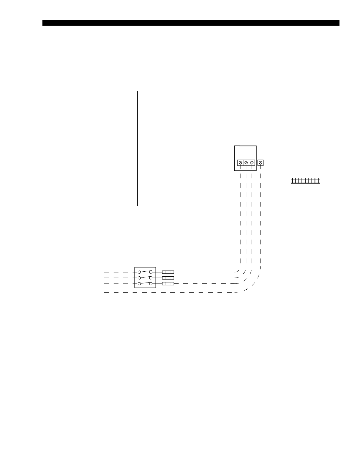
SINGLE-POINT POWER SUPPLY WIRING
WITH NON-FUSED DISCONNECT
FORM 100.50-EG12 (918)
NOTES
1. All eld wiring must be provided through a eld-supplied fused disconnect switch to the unit terminals (or optional molded disconnect
switch).
2. All electrical wiring must be made in accordance with all N.E.C. and/or local code requirements.
3. Minimum Circuit Ampacity (MCA) is based on U.L. Standard 1995, Section 36.14 (N.E.C. Section 440.34).
4. Maximum Dual Element Fuse size is based on U.L. Standard 1995, Section 36.15 (N.E.C. Section 440.22)
5. Use copper conductors only.
6. On units with an optional disconnect switch, the supplied disconnect switch is a “Disconnecting Means” as dened in the N.E.C. Section
100, and is intended for isolating the unit from the available power supply to perform maintenance and troubleshooting. This disconnect
switch is not intended to be a Load Break Device.
ld06415
FIGURE 7 - SINGLE-POINT POWER SUPPLY WIRING WITH NON-FUSED DISCONNECT
JOHNSON CONTROLS
71
Page 72

FORM100.50-EG12 (918)
Power Wiring: YPAL070–105 (Cont'd)
DUAL-POINT POWER SUPPLY WIRING
NOTES
1. All eld wiring must be provided through a eld-supplied fused disconnect switch to the unit terminals (or optional molded disconnect
switch).
2. All electrical wiring must be made in accordance with all N.E.C. and/or local code requirements.
3. Minimum Circuit Ampacity (MCA) is based on U.L. Standard 1995, Section 36.14 (N.E.C. Section 440.34).
4. Maximum Dual Element Fuse size is based on U.L. Standard 1995, Section 36.15 (N.E.C. Section 440.22)
5. Use copper conductors only.
6. On units with an optional disconnect switch, the supplied disconnect switch is a “Disconnecting Means” as dened in the N.E.C. Section
100, and is intended for isolating the unit from the available power supply to perform maintenance and troubleshooting. This disconnect
switch is not intended to be a Load Break Device.
FIGURE 8 - DUAL-POINT POWER SUPPLY WIRING
72
JOHNSON CONTROLS
Page 73

Field Control Wiring
FORM 100.50-EG12 (918)
FIGURE 9 - FIELD CONTROL WIRING
JOHNSON CONTROLS
ld08184
73
Page 74

FORM100.50-EG12 (918)
Field Control Wiring (Cont'd)
FIGURE 10 - FIELD CONTROL WIRING
74
JOHNSON CONTROLS
Page 75
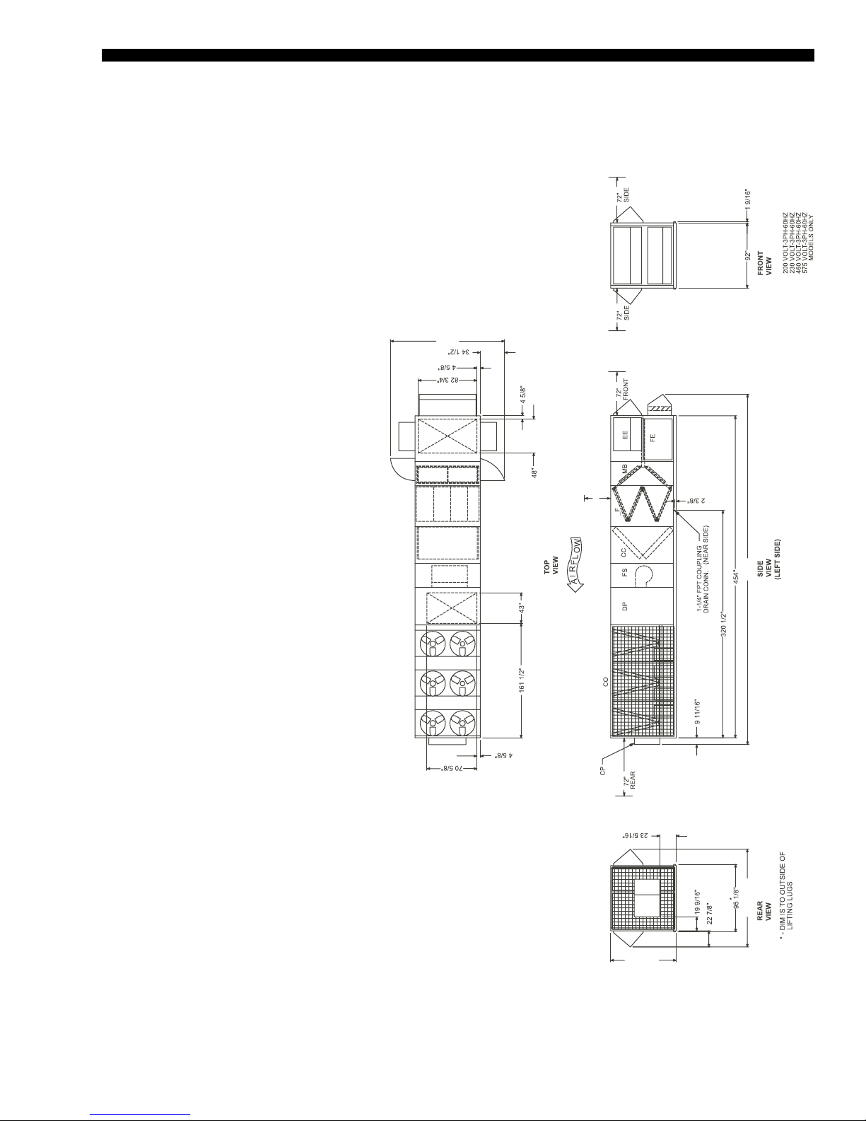
FORM 100.50-EG12 (918)
13’-5”
11’ - 5 13/16” 41’ - 2”
10’
7’ - 8 7/8”
General Arrangement Drawing – 70–80 Ton Models
BOTTOM SUPPLY / BOTTOM RETURN
SECTION DESCRIPTIONS:
EE = Economizer
FE = Fan Exhaust
MB = Mixing Box
_F = Filter Segments
CC = Cooling Coils
FS = Supply Fan
DP = Discharge Plenum
CO = Condenser Section
CP = Control Panel
of the Condensing Unit.
1. 10’ Clearance Minimal Over The Top
2. Only One Adjacent Wall Can Exceed
NOTES
FIGURE 11 - GENERAL ARRANGEMENT DRAWING
JOHNSON CONTROLS
Unit Height.
Units
3. 12’ Clearance Required to Adjacent
One Side.
4. 8’ Service Access Recommended on
Where Applicable, are Folded Inside
Unit for Shipment.
5. Economizer and Exhaust Hoods,
LD08128
75
Page 76

FORM100.50-EG12 (918)
13’ - 5”
10’
41’ - 2”
11’ - 5 13/16”
7’ - 8 7/8”
General Arrangement Drawing – 70–80 Ton Models (Cont'd)
LEFT SUPPLY / LEFT RETURN
SECTION DESCRIPTIONS:
EE = Economizer
FE = Fan Exhaust
MB = Mixing Box
_F = Filter Segments
CC = Cooling Coils
FS = Supply Fan
DP = Discharge Plenum
CO = Condenser Section
CP = Control Panel
of the Condensing Unit.
Unit Height.
Units
One Side.
Where Applicable, are Folded Inside
Unit for Shipment.
1. 10’ Clearance Minimal Over The Top
2. Only One Adjacent Wall Can Exceed
3. 12’ Clearance Required to Adjacent
4. 8’ Service Access Recommended on
5. Economizer and Exhaust Hoods,
NOTES
FIGURE 12 - GENERAL ARRANGEMENT DRAWING
76
JOHNSON CONTROLS
Page 77
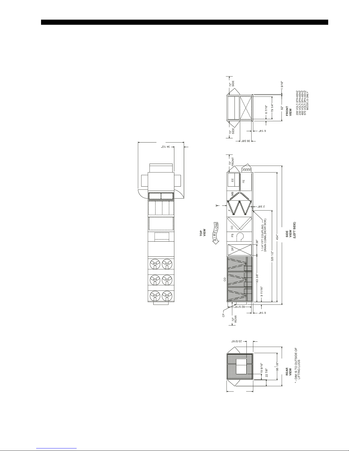
LEFT SUPPLY / FRONT RETURN
13’ - 5”
10’
41’ - 2”
11’ - 5 13/16”
7’ - 8 7/8”
SECTION DESCRIPTIONS:
EE = Economizer
FE = Fan Exhaust
MB = Mixing Box
_F = Filter Segments
CC = Cooling Coils
FS = Supply Fan
DP = Discharge Plenum
CO = Condenser Section
CP = Control Panel
FORM 100.50-EG12 (918)
of the Condensing Unit.
Unit Height.
Units
1. 10’ Clearance Minimal Over The Top
2. Only One Adjacent Wall Can Exceed
3. 12’ Clearance Required to Adjacent
4. 8’ Service Access Recommended on
NOTES
FIGURE 13 - GENERAL ARRANGEMENT DRAWING
JOHNSON CONTROLS
One Side.
Where Applicable, are Folded Inside
Unit for Shipment.
5. Economizer and Exhaust Hoods,
LD08130
77
Page 78

FORM100.50-EG12 (918)
13’ - 5”
10’
46’ - 5”11’ - 5 13/16”
7’ - 8 7/8”
31”
General Arrangement Drawing – 70–80 Ton Models (Cont'd)
EXTENDED CABINET / BOTTOM SUPPLY / BOTTOM RETURN
SECTION DESCRIPTIONS:
EE = Economizer
FE = Fan Exhaust
MB = Mixing Box
_F = Filter Segments
CC = Cooling Coils
FS = Supply Fan
DP = Discharge Plenum
CO = Condenser Section
CP = Control Panel
of the Condensing Unit.
Unit Height.
Units
One Side.
Where Applicable, are Folded Inside
Unit for Shipment.
er. If the Diffuser Factory Option is Not
Installed, Clearance, Downstream of
the Supply Fan Outlet is Required to
Provide Adequate Airow and Reduce
Air Pressure Drop.
1. 10’ Clearance Minimal Over The Top
2. Only One Adjacent Wall Can Exceed
3. 12’ Clearance Required to Adjacent
4. 8’ Service Access Recommended on
5. Economizer and Exhaust Hoods,
NOTES
6. Clearance Downstream of the Diffus-
FIGURE 14 - GENERAL ARRANGEMENT DRAWING
78
JOHNSON CONTROLS
Page 79

EXTENDED CABINET / LEFT SUPPLY / LEFT RETURN
13’ - 5”
10’
46’ - 5”
11’ - 5 13/16”
7’ - 8 7/8”
SECTION DESCRIPTIONS:
EE = Economizer
FE = Fan Exhaust
MB = Mixing Box
_F = Filter Segments
CC = Cooling Coils
FS = Supply Fan
FF = Final Filter
DP = Discharge Plenum
CO = Condenser Section
CP = Control Panel
FORM 100.50-EG12 (918)
of the Condensing Unit.
Unit Height.
Units
One Side.
Where Applicable, are Folded Inside
Unit for Shipment.
1. 10’ Clearance Minimal Over The Top
2. Only One Adjacent Wall Can Exceed
3. 12’ Clearance Required to Adjacent
4. 8’ Service Access Recommended on
5. Economizer and Exhaust Hoods,
6. Clearance Downstream of the Diffus-
NOTES
FIGURE 15 - GENERAL ARRANGEMENT DRAWING
er. If the Diffuser Factory Option is Not
Installed, Clearance, Downstream of
the Supply Fan Outlet is Required to
Provide Adequate Airow and Reduce
Air Pressure Drop.
ld08137
JOHNSON CONTROLS
79
Page 80

FORM100.50-EG12 (918)
13’ - 5”
10’
46’ - 5”
11’ - 5 13/16”
7’ - 8 7/8”
General Arrangement Drawing – 70–80 Ton Models (Cont'd)
EXTENDED CABINET / LEFT SUPPLY / FRONT RETURN
SECTION DESCRIPTIONS:
EE = Economizer
FE = Fan Exhaust
MB = Mixing Box
_F = Filter Segments
CC = Cooling Coils
FS = Supply Fan
DP = Discharge Plenum
CO = Condenser Section
CP = Control Panel
of the Condensing Unit.
Unit Height.
Units
One Side.
Where Applicable, are Folded Inside
Unit for Shipment.
er. If the Diffuser Factory Option is Not
Installed, Clearance, Downstream of
the Supply Fan Outlet is Required to
Provide Adequate Airow and Reduce
Air Pressure Drop.
1. 10’ Clearance Minimal Over The Top
2. Only One Adjacent Wall Can Exceed
3. 12’ Clearance Required to Adjacent
4. 8’ Service Access Recommended on
5. Economizer and Exhaust Hoods,
NOTES
6. Clearance Downstream of the Diffus-
FIGURE 16 - GENERAL ARRANGEMENT DRAWING
80
JOHNSON CONTROLS
Page 81

FORM 100.50-EG12 (918)
12’ - 5”
10’
43’ - 4 3/4”
11’ - 5 13/16”
7’ - 8 7/8”
General Arrangement Drawing – 90–105 Ton Models
BOTTOM SUPPLY / BOTTOM RETURN
SECTION DESCRIPTIONS:
EE = Economizer
FE = Fan Exhaust
MB = Mixing Box
_F = Filter Segments
CC = Cooling Coils
FS = Supply Fan
DP = Discharge Plenum
CO = Condenser Section
CP = Control Panel
of the Condensing Unit.
1. 10’ Clearance Minimal Over The Top
NOTES
FIGURE 17 - GENERAL ARRANGEMENT DRAWING
JOHNSON CONTROLS
Unit Height.
Units
2. Only One Adjacent Wall Can Exceed
3. 12’ Clearance Required to Adjacent
One Side.
4. 8’ Service Access Recommended on
Where Applicable, are Folded Inside
Unit for Shipment.
5. Economizer and Exhaust Hoods,
ld08131
81
Page 82

FORM100.50-EG12 (918)
12’ - 5”
10’
43’ - 4 3/4”
11’ - 5 13/16”
7’ - 8 7/8”
General Arrangement Drawing – 90–105 Ton Models (Cont'd)
LEFT SUPPLY / LEFT RETURN
SECTION DESCRIPTIONS:
EE = Economizer
FE = Fan Exhaust
MB = Mixing Box
_F = Filter Segments
CC = Cooling Coils
FS = Supply Fan
DP = Discharge Plenum
CO = Condenser Section
CP = Control Panel
of the Condensing Unit.
Unit Height.
Units
One Side.
Where Applicable, are Folded Inside
Unit for Shipment.
1. 10’ Clearance Minimal Over The Top
2. Only One Adjacent Wall Can Exceed
3. 12’ Clearance Required to Adjacent
4. 8’ Service Access Recommended on
5. Economizer and Exhaust Hoods,
NOTES
FIGURE 18 - GENERAL ARRANGEMENT DRAWING
82
JOHNSON CONTROLS
Page 83

LEFT SUPPLY / FRONT RETURN
12’ - 5”
10’
43’ - 4 3/4”
11’ - 5 13/16”
7’ - 8 7/8”
SECTION DESCRIPTIONS:
EE = Economizer
FE = Fan Exhaust
MB = Mixing Box
_F = Filter Segments
CC = Cooling Coils
FS = Supply Fan
DP = Discharge Plenum
CO = Condenser Section
CP = Control Panel
FORM 100.50-EG12 (918)
1. 10’ Clearance Minimal Over The Top
NOTES
FIGURE 19 - GENERAL ARRANGEMENT DRAWING
JOHNSON CONTROLS
of the Condensing Unit.
Unit Height.
Units
One Side.
2. Only One Adjacent Wall Can Exceed
3. 12’ Clearance Required to Adjacent
4. 8’ Service Access Recommended on
Where Applicable, are Folded Inside
Unit for Shipment.
5. Economizer and Exhaust Hoods,
ld08133
83
Page 84

FORM100.50-EG12 (918)
12’ - 5”
10’
49’ - 10 3/4”
11’ - 5 13/16”
7’ - 8 7/8”
36”
General Arrangement Drawing – 90–105 Ton Models (Cont'd)
EXTENDED CABINET / BOTTOM SUPPLY / BOTTOM RETURN
SECTION DESCRIPTIONS:
EE = Economizer
FE = Fan Exhaust
MB = Mixing Box
_F = Filter Segments
CC = Cooling Coils
FS = Supply Fan
FF = Final Filter
DP = Discharge Plenum
CO = Condenser Section
CP = Control Panel
of the Condensing Unit.
Unit Height.
1. 10’ Clearance Minimal Over The Top
2. Only One Adjacent Wall Can Exceed
NOTES
3. 12’ Clearance Required to Adjacent
Units
One Side.
Where Applicable, are Folded Inside
4. 8’ Service Access Recommended on
5. Economizer and Exhaust Hoods,
Unit for Shipment.
er. If the Diffuser Factory Option is Not
Installed, Clearance, Downstream of
the Supply Fan Outlet is Required to
Provide Adequate Airow and Reduce
Air Pressure Drop.
6. Clearance Downstream of the Diffus-
FIGURE 20 - GENERAL ARRANGEMENT DRAWING
84
JOHNSON CONTROLS
Page 85

12’ - 5”
10’
49’ - 10 3/4”
11’ - 5 13/16”
7’ - 8 7/8”
EXTENDED CABINET / LEFT SUPPLY / LEFT RETURN
SECTION DESCRIPTIONS:
EE = Economizer
FE = Fan Exhaust
MB = Mixing Box
_F = Filter Segments
CC = Cooling Coils
FS = Supply Fan
FF = Final Filter
DP = Discharge Plenum
CO = Condenser Section
CP = Control Panel
FORM 100.50-EG12 (918)
of the Condensing Unit.
Unit Height.
Units
One Side.
Where Applicable, are Folded Inside
Unit for Shipment.
er. If the Diffuser Factory Option is Not
Installed, Clearance, Downstream of
the Supply Fan Outlet is Required to
Provide Adequate Airow and Reduce
Air Pressure Drop.
1. 10’ Clearance Minimal Over The Top
2. Only One Adjacent Wall Can Exceed
3. 12’ Clearance Required to Adjacent
4. 8’ Service Access Recommended on
5. Economizer and Exhaust Hoods,
6. Clearance Downstream of the Diffus-
NOTES
FIGURE 21 - GENERAL ARRANGEMENT DRAWING
JOHNSON CONTROLS
LD08137
85
Page 86

FORM100.50-EG12 (918)
12’ - 5”
10’
49’ - 10 3/4”
11’ - 5 13/16”
7’ - 8 7/8”
General Arrangement Drawing – 90–105 Ton Models (Cont'd)
EXTENDED CABINET / LEFT SUPPLY / BOTTOM RETURN
SECTION DESCRIPTIONS:
EE = Economizer
FE = Fan Exhaust
MB = Mixing Box
_F = Filter Segments
CC = Cooling Coils
FS = Supply Fan
FF = Final Filter
DP = Discharge Plenum
CO = Condenser Section
CP = Control Panel
of the Condensing Unit.
Unit Height.
1. 10’ Clearance Minimal Over The Top
2. Only One Adjacent Wall Can Exceed
NOTES
3. 12’ Clearance Required to Adjacent
Units
One Side.
Where Applicable, are Folded Inside
4. 8’ Service Access Recommended on
5. Economizer and Exhaust Hoods,
Unit for Shipment.
er. If the Diffuser Factory Option is Not
Installed, Clearance, Downstream of
the Supply Fan Outlet is Required to
Provide Adequate Airow and Reduce
Air Pressure Drop.
6. Clearance Downstream of the Diffus-
FIGURE 22 - GENERAL ARRANGEMENT DRAWING
86
JOHNSON CONTROLS
Page 87

General Arrangement Drawing - Curb Layout
CURB LAYOUT DRAWING / 70–80 TON MODEL
FORM 100.50-EG12 (918)
CURB LAYOUT DRAWING / 90–105 TON MODEL
NOTES
1. Unit must be installed square and level.
2. Curb conguration for “bottom” return and “bottom” supply.
3. These drawings are not intended as construction documents for the eld fabricated roof curbs. Johnson
Controls will not be responsible for the unit t up, leak integrity, or sound level for installation using eld
fabricated roof curbs.
4. The YPAL unit does not have a base pan under the condensing section of the unit. Field fabricated roof
curbs must have a cap on the top of the condensing section of the curb to prevent moisture from entering
the space. The cap design must be sloped away from the supply duct opening to the end of the unit for the
drainage of the moisture off of the top of the cap.
FIGURE 23 - GENERAL ARRANGEMENT DRAWING
JOHNSON CONTROLS
87
Page 88

FORM100.50-EG12 (918)
General Arrangement Drawing - Curb Layout (Cont'd)
EXTENDED CURB LAYOUT DRAWING / 70–80 TON MODEL
EXTENDED CURB LAYOUT DRAWING / 90–105 TON MODEL
NOTES
1. Unit must be installed square and level.
2. Curb conguration for “bottom” return and “bottom” supply.
3. These drawings are not intended as construction documents for the eld fabricated roof curbs. Johnson Controls will not be responsible
for the unit t up, leak integrity, or sound level for installation using eld fabricated roof curbs.
4. The YPAL unit does not have a base pan under the condensing section of the unit. Field fabricated roof curbs must have a cap on the top
of the condensing section of the curb to prevent moisture from entering the space. The cap design must be sloped away from the supply
duct opening to the end of the unit for the drainage of the moisture off of the top of the cap.
FIGURE 24 - GENERAL ARRANGEMENT DRAWING
88
JOHNSON CONTROLS
Page 89

Hot Water/Steam Coil Connection Locations
C
D Supply
D Return
From Base Rail Bottom
Piping Connections
A
B
Coil
HOT WATER & STEAM
COIL CONNECTION
LOCATIONS
FORM 100.50-EG12 (918)
LD08119
TABLE 35 - FITTING LOCATION DIMENSIONS
UNIT SIZE
A B C D
Note 1 Note 2 Note 3 Note 4 Note 4 SUPPLY RETURN
SUPPLY
HOT WATER
70–80 254.60 285.60 6.25 45.60 16.00 2-inch FPS 2-inch FPS
90–105 283.10 319.80 6.25 50.10 15.50 2-inch FPS 2-inch FPS
STEAM
70–80 254.60 270.50 5.75 31.90 16.00 2-inch MPT 1.5-inch MPT
90–105 283.10 301.50 5.75 32.60 15.60 2-inch MPT 1.5-inch MPT
NOTES
1. Location of return line connection, horizontal from economizer corner post, in direction of airow
2. Location of supply line connection, horizontal from economizer corner post, in direction of airow
3. Location of both supply and return lines, horizontal from outside casing of unit, across direction of airow
4. Location of supply and return lines, vertical from bottom edge of base rail
MPT = Male Pipe Thread FPS = Female Pipe Sweat FPT = Female Pipe Thread
Hot Water Coil Connections w/ controls are valve connections facing bottom of the unit, at locations indicated.
Steam and Hot Water connections w/o controls are ttings connections facing side of the unit, at locations indicated.
D
RETURN
CONNECTION SIZES (INCHES)
JOHNSON CONTROLS
89
Page 90

FORM100.50-EG12 (918)
Power/Control Entry Drawing – 70-105 Ton Models
FIGURE 25 - POWER/CONTROL ENTRY DRAWING – 70 - 105 TON MODELS
90
LD19503
JOHNSON CONTROLS
Page 91

Guide Specifications
GENERAL
Scope
The requirements of the General Conditions, Supplementary Conditions, Division 1 and
drawings apply to all work herein.
Provide Microprocessor-controlled, air-cooled, double-wall construction outdoor packaged single package unit air conditioning product of the scheduled capacities and performance as shown and indicated on the Drawings, including but not limited to:
1. Single-piece single package unit package
2. Charge of refrigerant and oil
3. Electrical power and control connections
4. Supply and return duct connections
FORM 100.50-EG12 (918)
5. Factory start-up
Quality Assurance
All units are tested, rated or certified, as applicable, in accordance with the following standards, guidelines and codes:
1. All units shall meet the latest ASHRAE 90.1 minimum energy-efciency requirements (EER)
2. All units shall meet the latest ASHRAE 62 requirements for ventilation and indoor
air quality.
3. All units shall be rated in accordance with the ARI Standard 340/360
4. All units shall be tested to ANSI/UL 1995 and CAN/CSA C22.2 No. 236 standards
5. Gas heating units shall be designed in conform to ANSI Z21.47-2006/CSA2.3-2006
standards and be carry the ETL listed.
6. Units shall be ETL and ETL Canada listed
Manufacturers: The design shown on the drawing is based upon products of the manu-
facturer scheduled. Alternate equipment manufacturers shall be acceptable if equipment
meets the scheduled performance and complies with these specifications. If equipment
manufactured by manufacturer other than that scheduled is utilized, then the Mechanical
Contractor shall be responsible for coordinating with the General Contractor and all affected Subcontractors to insure proper provisions for installation of the furnished unit. This
coordination shall include, but not be limited to, the following:
1. Structural supports for units.
2. Roof curb transition.
3. Piping size and connection/header locations.
4. Electrical power requirements and wire/conduit and overcurrent protection sizes.
5. All costs incurred to modify the building provisions to accept the furnished units.
JOHNSON CONTROLS
91
Page 92

FORM100.50-EG12 (918)
Guide Specifications (Cont'd)
Warranty: Manufacturer shall warrant all equipment and material of its manufacture
against defects in workmanship and material for a period of eighteen (18) months from
date of shipment.
1. The warranty shall include parts only during this period.
2. The warranty shall not include parts associated with routine maintenance, such as
belts, air lters, etc.
Delivery and Handling
Unit shall be delivered to the job site fully assembled, wired, and charged with refrigerant
and oil by the manufacturer.
Unit shall be stored and handled per Manufacturer’s instructions.
All handling and storage procedures shall be per manufacturer’s recommendations.
Submittals
Shop Drawings: Shop drawing submittals shall include, but not limited to, the following:
drawings indicating components, dimensions, weights, required clearances, and location,
type and size of field connections, and power and control wiring connections.
Product Data: Product data shall include dimensions, weights, capacities, ratings, fan
performance, motor electrical characteristics, and gauges and finishes of materials.
Documentation:
1. Fan curves with specied operating point clearly plotted shall be provided.
2. Product data of lter media, lter performance data, lter assembly, and lter frames
shall be provided.
3. Electrical requirements for power supply wiring; including wiring diagrams for inter-
lock and control wiring shall be supplied. Factory and eld-installed wiring shall be
clearly indicated.
4. Operation and maintenance documentation shall be supplied in accordance with
Section 01830 – Operation and Maintenance, including but not limited to instruc-
tions for lubrication, lter replacement, compressor, motor and drive replacement,
coil cleaning, lter maintenance, spare parts lists, and wiring diagrams.
Warranties
Equipment shall include the manufacturer’s warranty not less than eighteen months from
the date of shipment.
Extended parts warranty [optional] shall be included for an additional 1 [5] years
Extended parts and labor warranty [optional] shall be included for an additional 1 [5] years
EQUIPMENT
Product Specification
Summary: Completely factory assembled unitized construction packaged single package
unit air conditioning unit including a factory-mounted and wired unit controller and sensors, single-point power connection 460V [208V/230V/575V] three-phase, 60Hz power
supply, outdoor air handling section with return and supply openings, discharge plenum,
direct-expansion refrigerant condensing section.
92
JOHNSON CONTROLS
Page 93

FORM 100.50-EG12 (918)
Factory Test: The refrigerant circuit shall be pressure-tested, evacuated and fully charged
with refrigerant and oil. The completed refrigerant circuit shall undergo a factory helium
leak test and undergo an automated operational run test and quality inspection prior to
shipment. The unit controller shall be configured and run tested at the factory to minimize
field setup time. If the unit is not configured and tested, then the manufacturer shall provide field start up and testing to ensure that the controller is functioning properly.
Unit Construction
Base Rail: The unit shall include an integral design base rail with lifting points clearly
marked and visible on the base rail and a 1-1/4-inch FPT connection for condensate
drainage. The unit base shall be designed with a recessed curb mounting location. The
recessed curb-mounting surface shall provide a continuous surface for field application of
curb gasketing to create a weather tight seal between the curb and unit.
Casing: Casing shall be complete post and panel construction with exterior skin. All pan-
els, doors, walls, uprights, floor panels and roofing shall be one-inch thick; 1-1/2 pound
density insulation. Units are specifically designed for outdoor installation.
Roof: The unit roof shall be bowed with the peak in the middle of the unit and sloped
to both sides of the unit for drainage. A drip lip shall run the length of the unit to prevent
water drainage down the side of the unit. Roof and sidewall seams shall be continuously
caulked and covered with formed galvanized seam caps. All panel fasteners shall be secured through standing seams to prevent fastener penetrations that are exposed to the
air stream.
Paint: Exterior painted surfaces are designed to withstand a minimum of 1,000 salt spray
hours when tested in accordance with ASTM B-117.
Markings and Diagrams: All necessary tags and decals to aid in the service and/or indicating caution areas shall be provided. Electrical wiring diagrams shall be attached to the
control panel access door.
Documentation: Installation and maintenance manuals shall be supplied with each unit.
Access Doors: Double wall access doors shall be provided in the fan, coil, filter and inlet
sections of the unit on both sides of the unit. Doors shall be double-wall construction with
a solid liner and a minimum thickness of 1-inch. Doors shall be attached to the unit with
piano-type stainless steel hinges. Latches shall be positive-action, creating an airtight
seal between the door and unit. Panels and doors shall be completely gasketed with
a closed-cell, neoprene gasket. Door tiebacks shall be provided for all doors to secure
doors while servicing.
Economizer Type
Select None or One of the Following
1. No Outside Air: the unit has no provisions for outside ventilation air.
2. Manual Outside Air Damper: A manually adjustable outside air damper capable of
admitting 0–25% outside air shall be provided.
3. Two-Position Outside Air Damper: A two position damper outside air damper ca-
pable of admitting 0–25% outside air shall be provided. The minimum position shall
be manually adjustable from 0–25%. Control shall be based on the occupied mode
of the unit. For occupied mode, the damper shall be open to the minimum position
and for unoccupied, it shall be closed.
JOHNSON CONTROLS
93
Page 94

FORM100.50-EG12 (918)
Guide Specifications (Cont'd)
4. Modulating Economizer: The economizer segment shall be designed to use outside air for cooling and ventilation and provide a means of exhausting air from the
air-handling unit. The segment shall consist of parallel acting low-leak dampers. The
return air, outside air and exhaust air dampers shall be sized for 100% of nominal
unit airow. The exhaust air damper assembly shall have a factory-assembled rain
hood. The rain hood shall have a drip-lip the full width of the hood to channel moisture away from the air being drawn into the unit.
Economizer Leakage
Select One of the Following
1. Damper assemblies are low-leak design. Damper blades are fabricated from a minimum of 16-gauge galvanized steel. Blade edges are covered with vinyl seals.
2. Damper assemblies have a maximum leakage rate of 10 CFM/ft2 at 1.0 inch water gauge (iwg) when tested in accordance with AMCA Standard 500, and have a
longevity of 60,000 damper opening and closing cycles, complying with the requirements of California Title 24.
Select One of the Following Types of Building Pressure Control
1. No Building Exhaust/Relief: The unit has no provisions to exhaust building return
air.
2. Barometric Relief Damper: Building air exhaust shall be accomplished through
barometric relief dampers installed in the return air plenum. The dampers open relative to the building pressure. The opening pressure shall be adjustable.
3. On/Off Fan Powered Exhaust: A twin double width, double inlet (DWDI) Class II
forward-curved centrifugal exhaust fan shall be provided to exhaust building return
air to relieve building static pressure. The fans shall be constant volume and operate based on either a building static pressure, or outside air damper position.
4. Powered Exhaust with Modulating Discharge Damper: A twin DWDI Class II
forward-curved centrifugal exhaust fan shall be provided to exhaust building return
air to relieve building static pressure. The fans shall operate at a constant volume
and operate based on building static pressure. Exhaust airow shall be modulated
via a parallel-acting control damper. The exhaust air dampers shall be sized for
100% of the exhaust airow.
5. Powered Exhaust with Variable Frequency Drive (VFD): A twin DWDI Class II
forward-curved centrifugal exhaust fan shall be provided to exhaust building re-
turn air to relieve building static pressure. Exhaust airow shall be modulated via a
factory-installed and commissioned variable frequency drive (VFD) with the same
nameplate horsepower as the supply fan motor.
6. Power Return Fan: Two single width, single inlet (SWSI) plenum fans shall be pro-
vided to draw return air from the building to the single package unit. An access door
shall be provided on at least one side of the unit for fan/motor access. The return fan
shall operate to maintain a constant pressure within the return plenum.
7. Power Return Fan: Two SWSI plenum fans shall be provided to draw return air
from the building to the single package unit. An access door shall be provided on
at least one side of the unit for fan/motor access. The return fan shall operate to
maintain a constant pressure within the return plenum. A discharge damper shall be
provided to modulate building exhaust. The damper shall be controlled via building
pressure. The return damper shall linked with the outside air damper to modulate
volumes of return and outside airows.
94
JOHNSON CONTROLS
Page 95

FORM 100.50-EG12 (918)
For Powered Exhaust or Return Fan Options Above, Use The Following
1. Fan Motor: Fan motors shall be NEMA design ball-bearing types with electrical
characteristics and horsepower as specied. Motors shall be 1750 RPM, open drip-
proof type [TEFC]. [Optional shaft grounding rings on motors increase motor longevity when applied with a VFD.] The motor shall be located within the unit on an
adjustable base.
Mountings: Fan and fan motor shall be internally mounted and isolated on a full
width isolator support channel using 1-inch springs [2-inch springs and seismic
restraints]. The fan discharge shall be connected to the fan cabinet using a flexible
connection to insure vibration-free operation.
Bearings and Drives: Fan bearings shall be self-aligning, pillow block or flanged
type regreaseable ball bearings and shall be designed for an average life (L50) of
at least 200,000 hours. All bearings shall be factory lubricated and equipped with
standard hydraulic grease fittings and lube lines extended to the motor side of the
fan. Fan drives shall be selected for a 1.5 service factor and anti-static belts shall be
furnished. All drives shall be fixed pitch. Fan shafts shall be selected to operate well
below the first critical speed and each shaft shall be factory coated after assembly
with an anti-corrosion coating.
Filter Section
Select a Filter Rack, Filter Media, and Switch if Desired
1. Angled Filter Rack: Two-inch throwaway lters shall be provided in an angled lter
rack.
2. Angled Filter Rack: Two-inch cleanable lters shall be provided in an angled lter
rack.
3. Angled Filter Rack: Two-inch MERV 8 carbon media lters shall be provided in an
angled lter rack.
4. Angled Filter Rack: Two-inch high efciency (30%) MERV 8 pleated lters shall be
provided in an angled lter rack.
5. Flat Filter Rack: 60–65% Efcient MERV 11 Rigid Filters with a two-inch high ef-
ciency MERV 8 pleated pre-lters shall be provided in a at lter rack.
6. Flat Filter Rack: 90–95% Efcient MERV 14 Rigid Filters with a two-inch high ef-
ciency MERV 8 pleated pre-lters shall be provided in a at lter rack.
7. Dirty Filter Alarm: A dirty lter switch shall be provided and wired to the single
package unit control panel. Upon closure of the switch, the controller shall display
a dirty lter fault. The setting of the switch can be changed manually to close at a
specied pressure drop across the lters.
Evaporator Section
1. Cooling Coil: Evaporator coils shall be direct expansion type with intertwined circu-
iting to assure complete coil face activity during part load operation. Coil tubes shall
be 3/8-inch OD copper, with internally enhanced tubes. Fins shall be enhanced mechanically expanded to bond with the copper tubes. Coil casing shall be fabricated
from heavy gauge galvanized steel. All coils shall be pressure tested at a minimum
of 450 psig.
JOHNSON CONTROLS
95
Page 96

FORM100.50-EG12 (918)
Guide Specifications (Cont'd)
2. IAQ Drain Pan: The main coil drain pan shall be double-sloped stainless steel with
a condensate connection through the base rail of the unit. Clearance between the
evaporator coil and the drain pan shall allow for easy access to the drain pan for
cleaning, and shall be visible for inspection without the removal of components.
3. Intermediate Drain Pan: Coils with nned height greater than 48 inches shall have
an intermediate drain pan extending the entire nned length of the coil. The intermediate pans shall have drop tubes to guide condensate to the main drain pan.
Supply Fan Section
1. Fan: The fan section shall be equipped with a single DWDI forward-curved [airfoil
optional on 70–85T but standard on 90–105T] centrifugal type wheels. An access
door shall be provided on both sides of the unit for fan/motor access.
a. Mountings: Fan and fan motor shall be internally mounted and isolated on a
full width isolator support channel using 1-inch [2-inch optional] springs [with
optional seismic restraints]. The fan discharge shall be connected to the fan
cabinet using a flexible connection to insure vibration-free operation.
b. Bearings and Drives: Fan bearings shall be self-aligning, pillow block or
flanged type regreaseable ball bearings and shall be designed for an average
life (L50) of at least 200,000 hours. All bearings shall be factory lubricated and
equipped with standard hydraulic grease fittings and lube lines extended to the
motor side of the fan. Fan drives shall be selected for a 1.5 service factor and
anti-static belts shall be furnished. All drives shall be fixed pitch. Fan shafts shall
be selected to operate well below the first critical speed and each shaft shall be
factory coated after assembly with an anti-corrosion coating.
c. Optional VFD Manual Bypass: A three contactor manual bypass shall be pro-
vided to permit replacement of the VFD in the event of a power failure.
2. Direct Drive Plenum (DDP) Supply Fan: The fan section shall be equipped with a
Single Width Single Inlet (SWSI) airfoil plenum wheel. Plenum fans shall be direct
drive. An access door shall be provided on both sides of the unit for fan/motor access.
a. Mountings: Fan and fan motor shall be internally mounted and isolated on a full
width isolator support channel using 1-inch springs [2-inch springs and seismic
restraints].
b. Acoustiweir™: Unit shall include a discharge air (DA) sound attenuation barrier.
The passive sound attenuator barrier shall be mounted on the downstream side
of the supply fan and shall block line-of-sight between the fan and the unit discharge opening. If not available, manufacturer must provide a sound attenuator
of at least 3 feet in length.
c. Thrust Restraints: Provide horizontal thrust restraints between air handling
unit casing and fan housing.
d. Seismic Snubber: Unit shall be supplied with seismic snubbers on the SWSI
plenum fan.
e. Supply Fan Airflow Measurement: The SWSI supply fan shall be supplied with
an airflow measurement device. Airflow measurement device shall be ca¬pable
of measurement accuracy of +/-5%. Airflow measurement ring and trans¬ducer
shall be supplied for integration into a field-supplied controller.
f. Fan Inlet Screen: Unit shall be provided with a fan inlet screen.
96
JOHNSON CONTROLS
Page 97

FORM 100.50-EG12 (918)
g. Safety Grate: Safety grates capable of supporting a 300 pound center load
shall be provided over bottom supply air (SA) opening.
3. Fan Motor: Fan motors shall be NEMA design ball-bearing types with electrical
characteristics and horsepower as specied. Motors shall be 1750 RPM, open drip-
proof type [TEFC optional]. [Optional shaft grounding rings on motors increase motor longevity when applied with a VFD.] The motor shall be located within the unit
on an adjustable base.
4. Variable Air Volume (VAV) Fan Control: Variable Air Volume (VAV) supply fan con-
trol shall be accomplished by using a VFD matched to the supply fan motor HP. The
VFD shall include an integral DC line reactor to reduce harmonic distortion in the
incoming and outgoing power feeds. If a DC line reactor is not provided, an AC line
reactor must be provided. Inlet guide vanes shall not be acceptable. VFD control
keypads shall be located in the control cabinet for accessibility and servicing while
the unit is operating.
Discharge Plenum
Select One of the Following Heat/No Heat Configurations:
1. Cooling Only: The discharge air temperature sensor shall be located in the dis-
charge plenum and be located such that it accurately measures the supply air temperature. Walls shall be lined with a solid liner to prevent erosion of the insulation
and separate insulation from the air stream.
2. Staged Gas Heat: The heating section shall include an induced draft furnace in two
stages [four stages or six stages] of heating capacity.
Heat Exchanger: The heat exchanger shall be constructed of tubular aluminized
steel [stainless steel], with stainless steel flue baffles and flue assembly.
Burner and Ignition Control: The burner shall include a direct-driven induced-draft
combustion fan with energy efficient intermittent pilot spark ignition, redundant main
gas valves with pressure regulator.
Combustion Air Fan: The inducer fan(s) shall maintain a positive flow of air through
each tube, to expel the flue gas and to maintain a negative pressure within the heat
exchanger relative to the conditioned space.
Safety Devices: A high limit controller with automatic reset to prevent the heat exchanger from operating at an excessive temperature shall be included. A centrifugal
switch on the induced draft fan motor shaft shall prevent ignition until sufficient airflow is established through the heat exchanger. A rollout switch shall provide secondary airflow safety protection. The rollout switch shall discontinue furnace operation if
the flue becomes restricted.
3. Modulating Gas Heat: The heating section shall include an induced draft furnace
JOHNSON CONTROLS
Flue: The furnace flue shall be shipped loose to protect it from damage during transit. The flue shall be field-mounted by the installing contractor. The flue outlet shall be
located above the unit to help prevent recycling of combustion gases back through
the heat exchanger. Agency Certification: Gas heating sections are ETL listed to both
US and Canadian safety standards.
in 8:1 modulation [16:1, 24:1] of heating capacity.
Heat Exchanger(s): The heat exchanger(s) shall be constructed of tubular aluminized steel [stainless steel], with stainless steel flue baffles and flue assembly.
97
Page 98

FORM100.50-EG12 (918)
Guide Specifications (Cont'd)
Burner(s) and Ignition Control: The burner(s) shall include a direct-driven induceddraft combustion fan with energy efficient intermittent pilot spark ignition, redundant
main gas valves with pressure regulator.
Combustion Air Fan(s): The inducer fan(s) shall maintain a positive flow of air
through each tube, to expel the flue gas and to maintain a negative pressure within
the heat exchanger relative to the conditioned space.
Safety Devices: A high limit controller with automatic reset to prevent the heat exchanger from operating at an excessive temperature shall be included. A centrifugal
switch on the induced draft fan motor shaft shall prevent ignition until sufficient airflow is established through the heat exchanger. A rollout switch shall provide secondary airflow safety protection. The rollout switch shall discontinue furnace operation if
the flue becomes restricted.
Flue: The furnace flue shall be shipped loose to protect it from damage during transit. The flue shall be field-mounted by the installing contractor. The flue outlet shall be
located above the unit to help prevent recycling of combustion gases back through
the heat exchanger.
Agency Certification: Gas heating sections are ETL listed to both US and Canadian
safety standards.
4. Electric Heat: An electric slip-in heater is installed within the single package unit
discharge plenum to provide the heating requirements per the schedule shown on
the plans. The electric heater is wired in such a manner as to provide a minimum of
two steps of capacity.
Heat Exchanger: The furnace is an industrial grade design using an open coil made
of the highest-grade resistance wire containing 80% nickel and 20% chromium. The
resistance coils are adequately supported in the air stream using ceramic bushings
in the supporting framework. Terminals of the coil are stainless steel with high temperature ceramic bushings.
Safety Devices: The primary high temperature protection is a manual reset type
thermal cut out. Secondary protection is a manual reset type thermal cut out. Secondary protection is a replaceable thermal link.
Agency Certification: The operation of the electric heater is an integral part of the
single package units control system. Power connection to the heater is through the
power panel for the unit. Electric heat is ETL certified to both US and Canadian safety
standards.
5. Hot Water Heating Coil: A hot water coil shall be installed in the single package
unit discharge plenum.
Construction: The hot water coil shall have 8 [10, 12, 14] fins per inch, 2 tubes per
circuit, and an 2-inch inlet and outlet connection. Primary surface shall be 1/2-inch
OD copper tube, staggered in direction of airflow. Connections have 1/4-inch FPT
drain plug on each connection. A structural galvanized steel casing shall protect the
coil. An intermediate coil support shall be provided. The coil shall be circuited to
provide free draining and venting, through one vent and drain. Freezestat shall be
provided to prevent coil freeze-up.
Testing: Completed coil, including headers, connections and return bends shall be
tested with 325 pounds compressed air under water. Coils shall be designed for operation at 250 psig design working pressure.
98
JOHNSON CONTROLS
Page 99

FORM 100.50-EG12 (918)
6. Steam Heating Coil: A steam heating coil shall be installed in the single package
unit discharge plenum.
Construction: The steam coil shall be constructed in the non-freeze style. The
steam coil shall have six fins per inch, an 2-inch inlet, and 1-1/2-inch outlet connection. Tubes shall be 1-inch OD seamless copper tubing with a minimum wall thickness of 0.035-inch and expanded into the fin collars for maximum fin-tube bond.
Inner distributing tubes shall be 5/8-inch OD seamless copper tubing with a minimum
wall thickness of 1/4 inch. All header connections shall be of red brass or steel, with
male pipe threads and silver braze to headers. Casing shall be galvanized steel. The
core shall be pitched in the direction of the condensate connection for proper drainage. Freezestat shall be provided to prevent coil freeze-up.
Testing: The completed coil, including headers and connections, shall be tested
underwater with 325 pounds. compressed air to ensure a leak free coil.
7. Diffuser Section: For applications with an extended discharge plenum with down-
stream ltration or heating, a diffuser section is provided. A diffuser shall be included
to distribute the airow from the fan evenly across the heating coil or lter bank to
optimize coil/lter life and effectiveness. The diffuser shall be sized for 50% free
area and provide adequate upstream and downstream clearance to minimize air-
side pressure drop.
For Extended Discharge Plenums, Select One of the Following:
1. Downstream Final Filter Rack: A 12-inch rigid lter rack and lters shall be provid-
ed downstream of the supply fan and diffuser segment for hospital applications. The
lter shall be 90–95% efcient MERV 14. A magnahelic pressure gauge shall be
included and visible from the outside of the unit for servicing and code compliance.
2. Blank Section: A blank section shall be provided downstream of the supply fan and
diffuser section.
Condenser Section
1. Condenser Fans: Condenser fans shall be matched up with compressors to op-
timize system control. Condenser fans shall be propeller type, directly driven by
permanently lubricated TEAO motor.
2. Condenser Coil: Microchannel condenser coils shall be constructed of parallel ow
aluminum alloy tubes metallurgically brazed to enhanced aluminum alloy ns. Coils
are congured in a V-bank conguration, with individual at coils rotated from the
vertical plane for protection from hail damage for each condensing circuit. Condens-
ing coils shall have a subcooler for more efcient, stable operation.
3. Compressors: Units shall use industrial-duty hermetic scroll compressors, piped
and charged with P.O.E. oil and R-410A refrigerant. Compressors shall have an
enlarged liquid carrying capacity to withstand rugged operating conditions. Compressor frame shall be cast iron, with cast iron xed and orbiting scrolls. Each com-
pressor shall feature a solid state protection module, designed to protect the compressor from over-temperature and over-current conditions. Compressors shall be
vibration-isolated from the unit, and installed in an easily accessible area of the unit.
All compressor-to-pipe connections shall be brazed to minimize potential for leaks.
Each compressor shall include a replaceable suction screen, discharge line check
valve, and oil sight glass.
JOHNSON CONTROLS
99
Page 100

FORM100.50-EG12 (918)
Guide Specifications (Cont'd)
4. Low Ambient: Compressors shall operate down to 0.0°F [optional] by monitor-
ing the refrigeration system discharge pressure and adjusting condenser airow
to maintain the proper head pressure to protect compressor operation. Refrigerant
pressure transducers shall be included and provide the discharge pressure on the
single package unit control display.
5. In-Line Liquid Line Driers [replaceable core liquid line driers]: Refrigerant piping includes check valves, thermal expansion valves with replaceable thermostatic
elements, high and low pressure switches, anti-recycling timing device to prevent
compressor restart for 5 minutes after shutdown.
6. Condenser Wire Grill [optional louvered condenser enclosure or no enclo-
sure]: The condenser section shall be enclosed by a wire grill [louvered or none]
condenser enclosure on the three exposed sides. Paint nish shall match the color
and salt spray specications of the unit exterior.
7. Hot Gas Bypass: Hot gas bypass piping shall be provided to enable compressor
unloading to as low as 5% to better match cooling demand at low loads, prevent
excessive cycling of the compressor, and reduce the risk of coil freeze-up.
8. Compressor sound treatment [optional]: Compressor sound blankets shall be
provided to attenuate radiated sound from the compressors.
9. Service Valves [optional]: Liquid, suction and discharge service valves shall be
included to provide a means of isolating the refrigerant charge in the system so that
the refrigeration system may be serviced without removing the charge of the unit.
Controls
1. Enclosure: Unit shall be shipped complete with factory congured, installed, wired
and tested single package unit controller housed in a rain and dust tight enclosure
with hinged, latched, and gasket sealed door.
2. Basic Controls: Control shall include automatic start, stop, operating, and pro-
tection sequences across the range of scheduled conditions and transients. The
single package unit controller shall provide automatic control of compressor start/
stop, energy saver delay and anti-recycle timers, condenser fans, and unit alarms.
Automatic reset to normal operation after power failure. Software stored in nonvolatile memory, with programmed setpoints retained in lithium battery backed real
time clock (RTC) memory for minimum 5 years. Eighty character liquid crystal display, descriptions and numeric data in English (or metric) units. The sealed keypad
shall include buttons for setpoints, display, entry, unit options & clock, and an on/
off switch.
3. Diagnostics: Upon startup, the controller shall run through a self-diagnostic check
to verify proper operation and sequence loading. The single package unit controller shall continually monitor all input and output points on the controller to maintain
proper operation. The unit shall continue to operate in a trouble mode or shut down
as necessary to prevent an unsafe condition for the building occupants, or to prevent damage to the equipment. In the event of a unit shutdown or alarm, the operating conditions, date and time shall be stored in the shutdown history to facilitate
service and troubleshooting.
100
JOHNSON CONTROLS
 Loading...