

Page 1
JOHNSON
Issue date
Revision
date
2017-3-1
Edition 01 Doc No. SM-TM-AF-011
Edition time
01
Page
Johnson Industries (Shanghai) Co.,Ltd
Document: R30 & R50 Service Manual
33
Approval Review Editor
Kyle. Schweitzer
Alex Tang Dora
1
Page 2
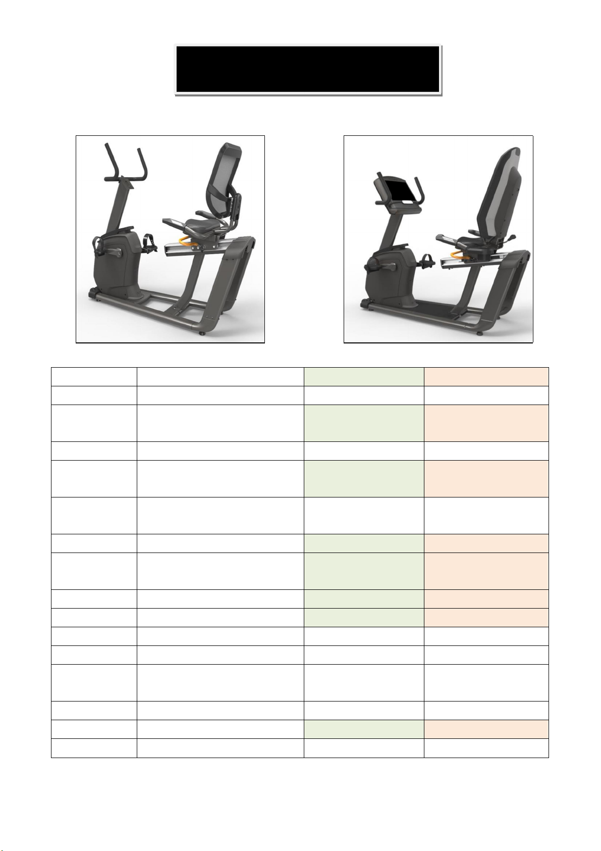
Product Browse
Matrix Retail R30 Matrix Retail R50
Specification
Model Name R30 R50
Frame Frame Type New recumbent frame New recumbent frame
Pedal Type Ratcheting Closure
*JD1A-B
Handle Bar Adjustment N/A N/A
Handle Bar Type Seat - Painted
Mast - Foam
Seat Adjustment Aluminum extrusion
*same as Matrix R1x
Seat Bottom Type Foam *Same as R20 Foam *Same as R40
Seat Back Type Mesh
*Same as R20
Drive System Flywheel Weight 10.5kg N/A
Resistance System Internal ECB Induction Brake
Crank Style Custom Custom
Power Supply 2A 2A
Power Requirements 110 - 120 Volt circuit
200 - 220 Volt circuit
Ratcheting Closure
*JD-62A - Blue
Seat - Painted
Mast - Dipped
Aluminum extrusion
*same as Matrix R1x
Mesh
*Same as R40
110 - 120 Volt circuit
200 - 220 Volt circuit
No. Transport Wheels
Remote Buttons No On grip pulse
Levelers Yes Yes
2 2
2
Page 3

Contents
CHAPTER 1: SERIAL NUMBER LOCATION ................................................................................................ 5
CHAPTER 2: CONSOLE INSTRUCTION
2.1 XR/XIR/XER CONSOLE ...................................................................................................................... 6
2.2 OPERATION GUIDE ........................................................................................................................... 6
2.3 CONSOLE DESCRIPTION-XR ............................................................................................................ 7
2.4 4 SOFTWARE UPDATING .................................................................................................................. 9
2.5 CONSOLE DESCRIPTION- XER/XIR .................................................................................................. 9
CHAPTER 3: TROUBLESHOOTING
3.1 ELECTRICAL DIAGRAM-CONSOLE ............................................................................................... 11
3.3.1 XR CONSOLE DIAGRAM .................................................................................................... 11
3.1.2 XER/XIR CONSOLE DIAGRAM ........................................................................................... 11
3.2 ELECTRICAL DIAGRAM-FRAME .................................................................................................... 12
3.2.1 R30 FRAME WIRING SCHEMATIC ..................................................................................... 12
3.2.2 R50 FRAME WIRING SCHEMATIC ..................................................................................... 13
3.2 ECB/LCB Wiring Instructions ........................................................................................................... 14
3.3.1 ECB WIRING INSTRUCTIONS (R30) .................................................................................. 14
3.3.2 MCB WIRING INSTRUCTIONS(R50) ................................................................................... 14
3.4 Troubleshooting .............................................................................................................................. 14
3.4.1 NO POWER TO THE CONSOLE ........................................................................................... 15
3.4.2 TROUBLESHOOTING – SPEED DOES NOT DISPLAY .......................................................... 15
3.4.3 TROUBLESHOOTING – NO HAND PULSE RESPONSE ....................................................... 16
3.4.4 TROUBLESHOOTING – SPEAKER/AUDIO ISSUES ............................................................... 16
3.4.5 TROUBLESHOOTING – RADIO FREQUENCY ISSUES ......................................................... 17
3.4.6 TROUBLESHOOTING – NO RPM DISPLAYED ...................................................................... 18
3
Page 4

3.4.7 TROUBLESHOOTING – NO RESISTANCE OR INCORRECT RESISTANCE ......................... 19
3.4.8 TROUBLESHOOTING – HEART RATE ISSUES..................................................................... 21
3.4.9 TROUBLESHOOTING-HANDLEBAR KEYPAD ISSUE…………………………………………….22
CHAPTER 4: PART REPLACEMENT GUIDE
4.1 CONSOLE REPLACEMENT ........................................................................................................... 23
4.2 HANDLEBAR REPLACEMENT ....................................................................................................... 24
4.3 PEDAL REPLACEMENT ................................................................................................................. 24
4.4 CRANK REPLACEMENT ................................................................................................................ 25
4.5 SIDE COVERS REPLACEMENT ..................................................................................................... 25
4.6 MCB REPLACEMENT .................................................................................................................... 27
4.7 STABILIZER COVERS REPLACEMENT ......................................................................................... 28
4.8 CUP HOLDER REPLACEMENT ...................................................................................................... 28
4.9 HEART RATE WIRE REPLACEMENT ............................................................................................ 29
4.10 SEAT REPLACEMENT ................................................................................................................. 30
4.11 ADJUSTMENT BAR REPLACEMENT ........................................................................................... 31
4.12 DRIVE BELT REPLACEMENT………………………………………………………………………………32
4.13 DRIVE AXLE REPLACEMENT………………………………………………………………………………33
4
Page 5
CHAPTER
1: Serial
Number
Location
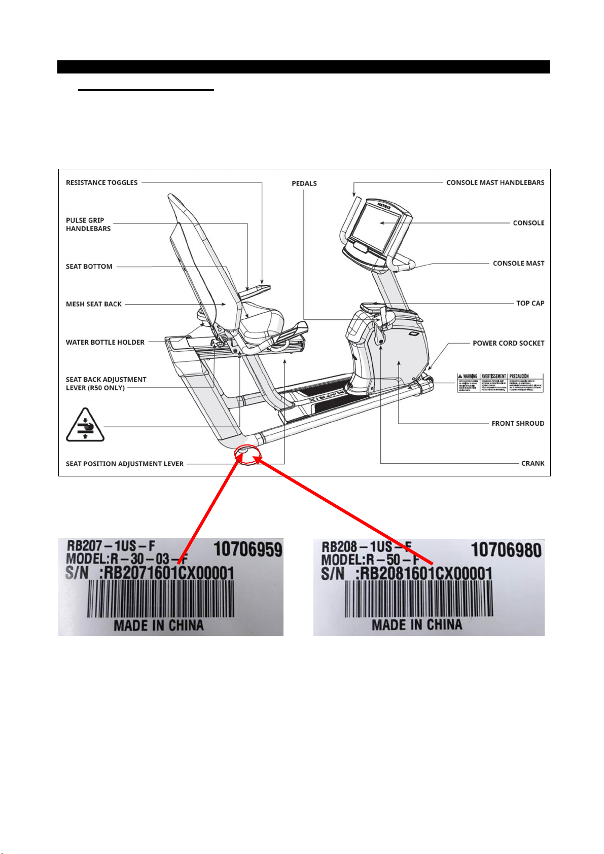
1.1 Serial Number Location
MATRIX R30/R50 BIKE FRAME
5
Page 6
CHAPTER
2: Console
Instruction
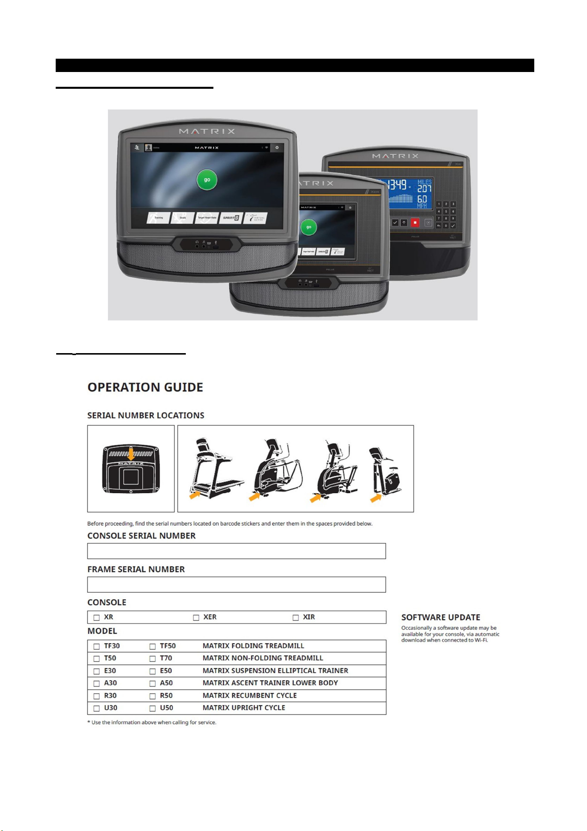
2.1 XR/XIR/XER CONSOLE
2.2 OPERATION GUIDE
6
Page 7
CHAPTER
2: Console
Instruction
2.3 CONSOLE DESCRIPTION-XR
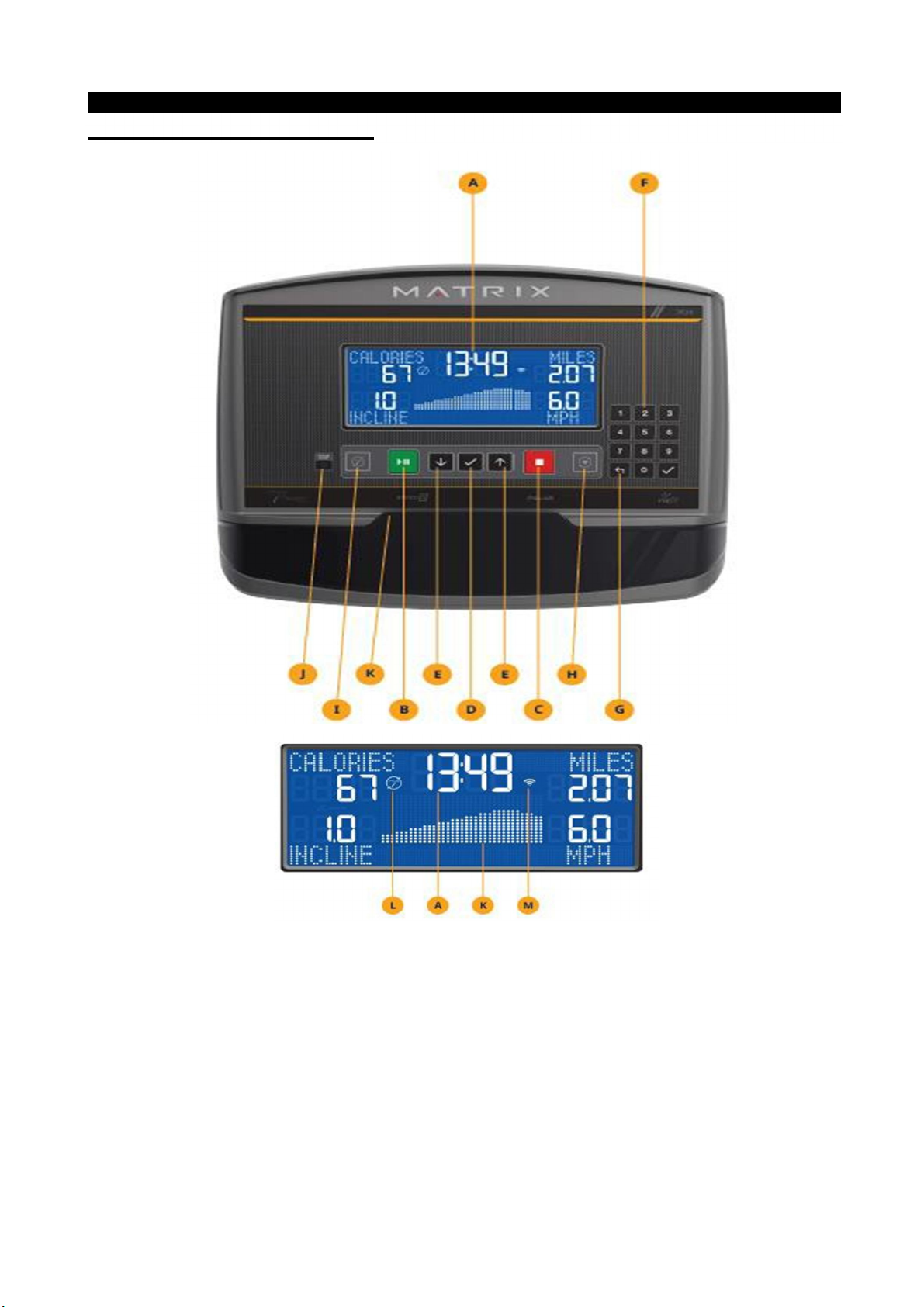
XR CONSOLE DESCRIPTION
Note: There is a thin, protective sheet of clear plastic on the overlay of the console that should be removed
before use.
A) LCD DISPLAY WINDOW: Displays workout feedback, program profile and more.
B) GO/PAUSE: Press to start, pause or resume your workout.
C) STOP: Press to stop your workout. Press and hold for 3 seconds to reset the console.
7
Page 8

CHAPTER
2: Console
Instruction
2.3CONSOLE DESCRIPTION-XR-CONTINUED
D) ENTER: Confirm each program setting. Press to change display feedback during workout. Press and hold to
scan.
E) ARROWS: Used to adjust program settings.
F) NUMBER KEYPAD: Used to enter XID login or program data during program setup. Also used to adjust
speed/resistance level during workout. Press to confirm setting.
G) BACK: Go to previous program setting.
H) WI-FI CONNECT & SYNC: Press to connect to wireless Internet. See BEFORE YOU BEGIN section for
more info.
I) PASSPORT CONNECT & SYNC: Press to connect your Passport box for Virtual Active programming.
Passport Player is sold at your retailer or at www.passportplayer.com
J) ENERGY SAVER LIGHT: Indicates if machine is in energy saver mode. Press any key to wake up the
machine.
K) READING RACK: Holds reading material or electronic device.
XR DISPLAY DESCRIPTION
A) TIME: Is always shown in the larger, central portion of the display. Shown as minutes: seconds. View
the time remaining or the time elapsed in your workout.
B) INCLINE: Shown as percent. Indicates the incline of your walking or running surface (Treadmills and
Ascents only).
C) DISTANCE: Shown as Miles or Kilometers* based on your default setting. Indicates distance traveled or
distance remaining during your workout.
D) SPEED: Shown as MPH or KPH* based on your default setting. Indicates how fast the footpads/pedals are
moving.
E) CALORIES: Total calories burned or calories remaining to burn during your workout.
F) HEART RATE: Shown as BPM (beats per minute). Used to monitor your heart rate (when wearing a
wireless heart rate strap or when contact is made with both pulse grips).
G) RESISTANCE (RES): Shows the current resistance level (Bikes, Ellipticals, Ascents only).
H) RPM: Revolutions Per Minute (Bikes, Ellipticals, Ascents only).
I) WATTS: Displays current user power output (Bikes, Ellipticals, Ascents only).
J) PACE: Indicates how many minutes it takes to complete a mile based on your current speed (Treadmills
only).
K) PROGRAM PROFILE: The dot matrix will show the program profile as you progress through your workout.
Profile represents incline, resistance or speed (depending on model type and workout type).
L) PASSPORT: Indicates Passport box connection is present.
M) WI-FI: Indicates wireless connection is present and the strength (low, medium, high). Flashes when Wi-Fi
is trying to connect.
* Default is set during console install. If logged in with XID, the default is set by user profile.
8
Page 9
CHAPTER
2: Console
Instruction
2.4 Software Updating
Update console software with the software updating tool.
b. Load the software update onto the USB flash drive. Insert the USB flash drive into the USB port; the
console will update automatically.
c.
If the software has updated successfully, the console will start initial setup and display the software version.
d. Remove the USB flash drive.
2.5CONSOLE DESCRIPTION-XER/XIR
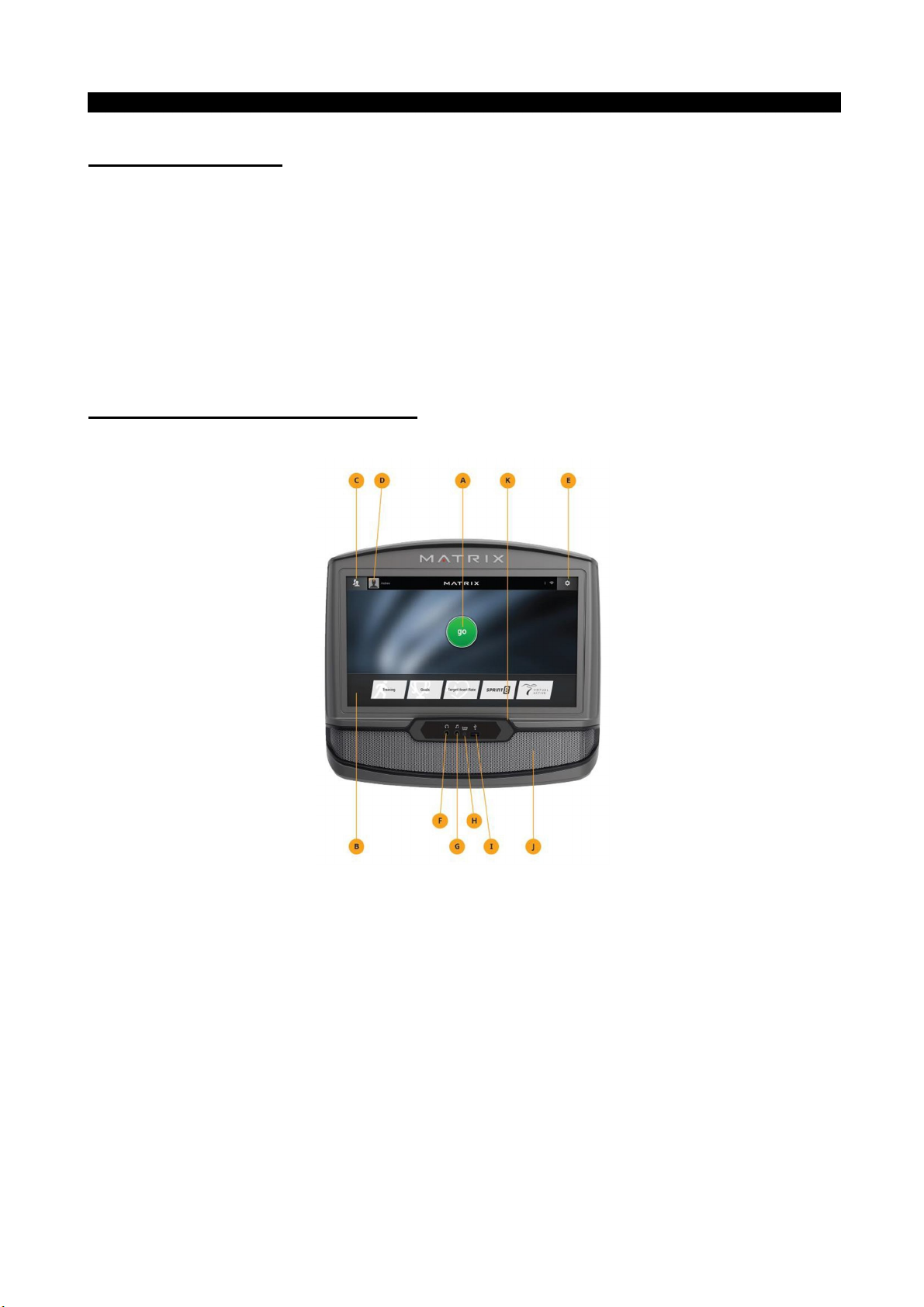
XER/XIR CONSOLE DESCRIPTION
Note: There is a thin protective sheet of clear plastic on the overlay of the console that should be removed
before use. The XER and XIR have a fully-integrated touchscreen display. All information required for workouts
is explained onscreen. Exploration of the interface is highly encouraged.
A) GO: Press to begin a quick start program.
B) PROGRAM BUTTONS: Press to select from a number of preset programs.
C) USER MENU: Select an existing User, Guest or add a User.
D) USER SETUP: Allows you to edit User Information.
E) SETTINGS MENU: Access to Volume Controls, Bluetooth Pairing, Wi-Fi Setup, Sync Passport, Machine
defaults and more.
9
Page 10

CHAPTER
2: Console
Instruction
F) HEADPHONE JACK: Plug your headphones into the console to use them instead of the console
speakers.
G) AUDIO IN: Plug your media player into the console using the included audio adaptor cable.
H) ENERGY SAVER LIGHT: Indicates if machine is in energy saver mode. Press a speed/incline/resistance
button to wake up the machine.
* USB PORT: Access media from compatible devices (XIR only) or use to charge devices that draw up to 5 amp.
Also used for software updates.
I) SPEAKERS: Audio plays through the speakers.
J) READING RACK: Holds reading material or electronic device.
*
10
Page 11
CHAPTER
3: Troubleshooting
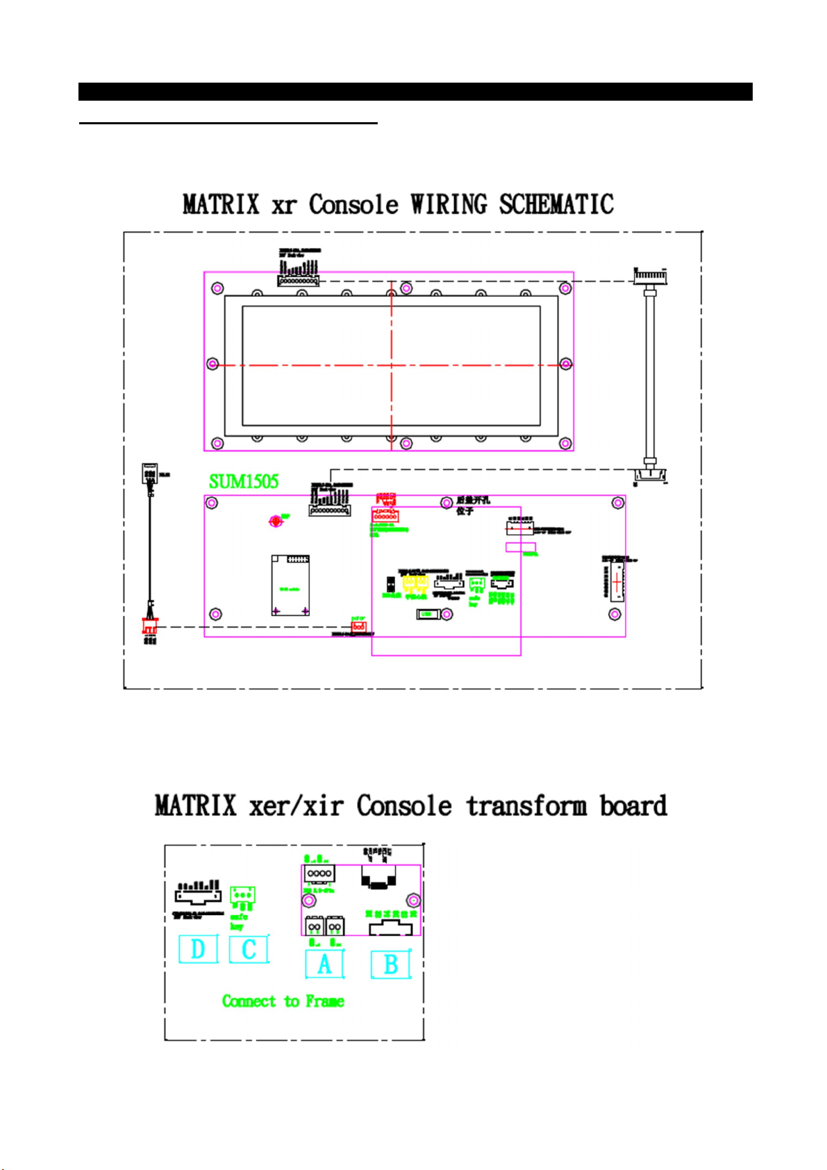
3.1ELECTRICAL DIAGRAM-CONSOLE
3.1.1 XR CONSOLE DIAGRAM
3.1.2 XER/XIR CONSOLE DIAGRAM
11
Page 12

CHAPTER
3: Troubleshooting
3.2 ELECTRICAL DIAGRAM-FRAME
3.2.1 R30 FRAME WIRING SCHEMATIC
12
Page 13

CHAPTER
3: Troubleshooting
3.2 ELECTRICAL DIAGRAM-FRAME-CONTINUED
3.2.2 R50 FRAME WIRING SCHEMATIC
13
Page 14

CHAPTER
3: Troubleshooting
3.3 ECB/LCB WIRING INSTRUCTIONS
3.3.1 ECB WIRING INSTRUCTIONS (R30)
N1
N2
N3
N1------- Power light
N2------- Speed sensor cable socket Console set cable socket
N3------- Console cable
14
Page 15

CHAPTER
3: Troubleshooting
3.3 ECB/LCB WIRING INSTRUCTIONS
3.3.2 MCB WIRING INSTRUCTIONS (R50)
N4
N1------- Power light
N2------- Speed sensor cable socket Console set cable socket
N3------- Console cable
N4 ------ Generator / Induction Brake/Magnet
15
Page 16

CHAPTER
3: Troubleshooting
3.4 TROUBLE SHOOTING
3.4.1 TROUBLESHOOTING – NO POWER TO THE CONSOLE
Symptom:
Console does not light up.
Possible Reason:
a. The power adaptor is not correct or is defective.
b. The console cable has a bad connection or is defective.
c. The console is defective.
Solution:
a. The adaptor for this model is 12V - 2A. Check to make sure the power adaptor on the unit is correct.
Test the power adaptor on a known good outlet. Replace the adaptor if it is defective.
b. Check the connection of the console cable at the console. Unplug the console cable from the console,
and use a multi-meter to check the voltage through the console cable. Normally it should be 12VDC. If
no voltage is present, the console cable is defective; replace it.
c. If the voltage through the console cable is 12VDC, the console is defective, replace it.
3.4.2 TROUBLESHOOTING – SPEED DOES NOT DISPLAY
Symptom:
The speed value does not display on the console.
1. Unplug the power cord, remove the console and check that all connections to the console are secure and
Solution:
not damaged or pinched.
16
Page 17

CHAPTER
3: Troubleshooting
3.4.2 TROUBLESHOOTING –SPEED DOES NOT DISPLAY---CONTINUED
2. Remove the side cover and check to see if the sensor wire is firmly connected.
3. Check to see if one corner of the sensor is aligned with the magnet and that the distance is less than
5mm.
3.4.3 TROUBLESHOOTING –NO HAND PULSE RESPONSE
Symptom:
The console does not display the heart rate during exercise.
Solution:
a. The user must hold one grip sensor in each hand.
b. Maintain moderate pressure while holding onto the heart rate handlebars.
c. Check to see if the wires are firmly connected to the sensor.
3.4.4 TROUBLESHOOTING – SPEAKER/AUDIO ISSUES
Symptom:
The speaker or headphones have no sound output.
Possible Reason:
a. The speaker wire is not firmly connected to the UCB.
b. The audio short circuit terminal is missing.
c. The software is obsolete.
d. The head phone wire or board is defective.
Solution:
a. Confirm whether the speaker wire is firmly connected to the UCB.
b. If firmly connected, make sure that the audio output short-circuit terminal is present and tight.
c. Update the console software (see Section 2.4).
d. If the speakers have sound output, but the headphones do not, replace the headphone wire. If problems
persist, replace the headphone board.
17
Page 18

CHAPTER
3: Troubleshooting
3.4.5 TROUBLESHOOTING – RADIO FREQUENCY ISSUES
Symptom:
The Radio Frequency Board (RF Board) cannot connect with Passport.
Possible Reason:
a. The Passport keys are not functional.
b. The FFC wire is damaged or disconnected.
c. The console is defective.
Solution:
a. Make sure that the Passport keys are functional.
b. Confirm whether the FFC wire is firmly connected, not broken or damaged. Replace if needed.
c. If above connections are all OK, replace the console.
18
Page 19

CHAPTER
3: Troubleshooting
3.4.6 TROUBLESHOOTING –NO RPM DISPLAYED
Symptom:
No RPM shown on the console.
Possible Reason:
a. Bad connection between the console cable and the console, or a damaged cable.
b. The speed sensor wire is damaged or not working.
c. The magnet is not present on the drive pulley.
d. The console is defective.
Solution:
a. Check the connection of the console cable at the console; make sure there are no kinks or pinches in
the console cable. Replace the cable if any damage is found.
b. Check the connection of the speed sensor wire at the ECB motor. Also check the gap between the
speed sensor and the magnet on the pulley. It should be within 5mm. Adjust the gap if it is too big.
c. Install a new magnet.
d. Replace the console set.
19
Page 20

CHAPTER
3: Troubleshooting
Using the photos on page
3.4.7 TROUBLESHOOTING – NO RESISTANCE OR INCORRECT RESISTANCE
1. General information:
Symptom Possible Cause Test Procedure Repair
No resistance change or
erratic or continuous
resistance change.
Tension cable is not connected
to the brake or has failed
Failed or improper power
supply
Failed console cable.
Failed servomotor
Failed console. Replace console.
The steel rope of the magnet
system is not routed correctly.
Verify that the tension
cable is connected to the
break or has not failed.
Perform voltage check on
adapter.
-Verify the adapter is the
correct voltage.
- Verify console cable is
not pinched or damaged
-Perform voltage check on
console cable.
-Perform voltage check on
servomotor.
Reattach cable.
Replace power supply
Replace console cable
Replace servomotor.
Re adjust position of
the magnet
29 for reference, check
The quick key on handle bar
was used wrong wire
the quick key wire
connection points to
Replace new quick
key connection wire
make sure they are
attached correctly.
Resistance is Too Hard
or Too Weak.
Tension cable is not
connected to the brake or has
failed.
Magnetic brake is positioned
improperly.
The inside magnet is defective.
Verify that the tension
cable is connected to the
brake or has not failed.
-Verify the correct
Position of magnetic
brake.
- Verify the of magnetic
brake.
Reattach cable.
Reposition the
magnetic brake
Replace new magnetic
brake
20
Page 21

CHAPTER
3: Troubleshooting
R30
Solution:
a. Check if the console shows RPM value. If it does not, refer to troubleshooting for NO RPM
DISPLAYED in Section 3.4.6
b. Remove the front shrouds. Turn on the console, and check the ECB motor. At resistance level 1, the
head of the steel rope should point towards the top right side (around 45 degrees – Fig A). If the head of
the steel rope points toward the bottom or left side, the resistance will be reversed; adjust the head of the
steel rope to the correct position.
c. Press the LEVEL UP key to adjust the resistance.
(1). If the ECB motor does not move, the resistance will not change. The ECB motor or console
cable is defective. Check the console cable connection at the ECB motor (Fig B). Use a multi-meter
to measure the voltage through the console cable. It should be 12VDC.
(2). If there is no voltage present, the console cable is defective. Replace the console cable.
(3). If the voltage is 12VDC, the ECB motor is defective. Replace the ECB motor.
(4). If the ECB motor does move, the resistance can be adjusted. If the resistance is still too high,
check the gap between the orange block and the bottom of the ECB track (Fig C). It should be within
1-2 mm of the bottom of the ECB track. If the gap is bigger than 1-2 mm, the resistance will be
higher than normal. Adjust the cable to the correct gap range (Fig D).
d. If all above conditions are OK, and the resistance is still too high, the inside magnet is defective.
Replace the ECB as the last step.
21
Page 22

CHAPTER
3: Troubleshooting
R50
1. Check the Connection wire between consoles to MCB. Try to unplug and then plug in the connector
(Page 14, CN2);
2. Check the connection wire between MCB and Induction Brake/Magnet Try to unplug and then plug in the
connector (Page 14, CN4);
3. Check the connection wire between quick key pad and console. Be sure not use wrong connection wire
Quick key on handlebar right/left (Fig1) /Handlebar connection to console. (Fig2)
Fig1
. Fig2
3.4.8. TROUBLESHOOTING – HEART RATE ISSUES
Symptom:
The console does not display heart rate or it is consistently inaccurate.
Possible Reason:
a. The heart rate grips are not connected correctly.
b. The heart rate wiring is damaged.
c. The heart rate board or console is defective.
22
Page 23

CHAPTER
3: Troubleshooting
Solution:
a. Remove the 2 screws holding the 2 halves of the heart rate grip together and check to make sure it is
firmly connected, with no breaks.
b. Check continuity of the HR grip wiring.
Place one terminal of a multi-meter set for resistance on the HR grip wiring at the HR grip, and
the other terminal on the HR grip wiring at the console. An ohm reading of around 1 should be
expected; if the reading is higher than 1, replace the HR grip wiring.
c. If the HR grip and wiring is confirmed to be good, replace the console
3.4.9. TROUBLESHOOTING –Handlebar keypad ISSUES
Symptom:
The handlebar keypad does not react or it is consistently inaccurate.
Possible Reason:
a. The handlebar keypad connection wire does not connect correctly.
b. The handlebar keypad connection wire is incorrect
c The handlebar keypad connection wiring is damaged.
d. The handlebar keypad board or console is defective.
Solution:
a. Remove the 3 screws holding the 2 halves of the handlebar together and check to make sure it is firmly
connected, with no breaks.
b. Check continuity of the Handlebar connection wiring.
Place one terminal of a multi-meter set for resistance on the handlebar wiring at the Handlebar, and
the other terminal on the quick key pad wiring at the console. An ohm reading of around 0 should be
expected; if the reading is higher than 0, replace the quick key wiring.
c. If the handlebar connection wiring is confirmed to be good, replace the console
.
23
Page 24

CHAPTER
4: Part
Replacement
Guide
4.1 CONSOLE REPLACEMENT
1) Remove the 5 screws holding the console back cover to the frame (Figure A).
2) Remove the 4 screws holding the console to the frame (Figure B).
3) Disconnect the console cable and HR connections from the defective console and remove the console
(Figure C).
FIGURE A FIGURE B
FIGURE C
3) Reinstall the wire connections to the new console.
4) Carefully push the wires into the console and mast until they are clear of the console/mast connection
and attach the console to the mast using the 4 screws.
24
Page 25

CHAPTER
4: Part
Replacement
Guide
4.2 HANDLEBAR REPLACEMENT
1) Remove the 2 screws holding the handlebar. (Figure A).
2) Install a new handlebar.
FIGURE A
4.3 PEDAL REPLACEMENT
1) Loosen and remove the screw holding the pedal to the crank (Figure A).
2) Install a new pedal.
FIGURE A
25
Page 26

CHAPTER
4: Part
Replacement
Guide
4.4 CRANK REPLACEMENT
1) Loosen and remove the screw holding the crank to frame (Figure A).
2) Install a new crank.
FIGURE A
4.5 SIDE COVERS REPLACEMENT
1) Remove the two top covers by hand (Figure A and B)
2) Remove the mast by removing the four screws. (Figure C).
FIGURE A FIGURE B
FIGURE C
26
Page 27

CHAPTER
4: Part
Replacement
Guide
4.5 SIDE COVERS REPLACEMENT---CONTINUE
3) Remove the top cover by loosening and removing the four screws. (Figure D and E)
FIGURE D FIGURE E
4) Remove crank arm (see section 4.4)
5) Remove the crank by loosening and removing the four screw. (Figure F and G)
FIGURE F FIGURE G
5) Remove the side cover by removing the 7 screws on both the left and right side covers. (Figure H and I)
FIGURE H FIGURE I
6) Reverse the steps to install new covers.
27
Page 28

CHAPTER
4: Part
Replacement
Guide
4.6 MCB REPLACEMENT
1) Remove side cover (see section 4.5)
2) Remove the LCB by removing the 2 screws (Fig A).
3) Install a new LCB. (Fig B)
4) Reverse step 1
Fig A Fig B
Note: Wear an ESD strip when handling and installing the MCB.
28
Page 29

CHAPTER
4: Part
Replacement
Guide
4.7STABILIZER COVERS REPLACEMENT
1) Remove the front stabilizer by removing the two screws underneath the frame (Figure A)
2) Remove the 4 screws to remove the central cover (Figure B).
3) Reverse the steps to install a new cover.
FIGURE A FIGURE B
4.8 CUP HOLDER REPLACEMENT
1) Remove the 2 screws to remove the cup holder (Figure A).
2) Install a new cup holder.
FIGURE A
29
Page 30

CHAPTER
4: Part
Replacement
Guide
4.9 Heart rate replacement
1) Remove the 3 screws (Figure A & Figure B).
2) Gently pull out the heart rate wire (Figure B).
3) Reverse the steps to install a new heart rate wire.
4) Connect the heart rate wire to the console by following the path shown from A to B (FIGURE-D)
FIGURE A FIGURE B
FIGURE C FIGURE D
30
Page 31

CHAPTER
4: Part
Replacement
Guide
4.10 SEAT REPLACEMENT
1) Remove the 4 screws to disassemble the back cover (Figure A) and then remove the seat mast (Figure
B).
2) Install a new seat.
FIGURE A FIGURE B
31
Page 32

CHAPTER
4: Part
Replacement
Guide
4.11 ADJUSTMENT BAR REPLACEMENT
1) Remove the 2 screws to disassemble the front cover (Figure A) and or the back cover (Figure B).
FIGURE A FIGURE B
2) Remove the (front or rear) 2 screws corresponding to step one (Figure C and D).
3) Reverse the steps to install a new adjustment bar.
FIGURE C FIGURE D
32
Page 33

CHAPTER
4: Part
Replacement
Guide
4.12. DRIVE BELT REPLACEMENT
1. REMOVE SIDE COVER (SEE SECTION 4.5)
2. Put the drive belt on the wheel (FIGURE-A)
FIGURE A
3. Measure belt tension that it should be 200HZ -220HZ (FIGURE-B)
FIGURE B
4. Reverse Step 1
33
Page 34

CHAPTER
4: Part
Replacement
Guide
4.13 .DRIVE AXLE REPLACE
1. REMOVE SIDE COVER (SEE SECTION 4.5)
2. Insert the wheel with C3 Bearing (FIGURE-A)
FIGURE A FIGURE B
3. Add C buckle (FIGURE-B)
4. Press bearing by fixture (FIGURE-C)
Note: An alternative method is to position the old bearing over the new bearing, and then use a mallet to pound
against the old bearing until the new bearing is pressed in place. Be careful not to directly hit the new bearing.
5. Roll the wheel to see if smooth (FIGURE-D)
FIGURE C FIGURE D
34
 Loading...