

Page 1
Pub. No. 6902118
Issued: 2008-10-15
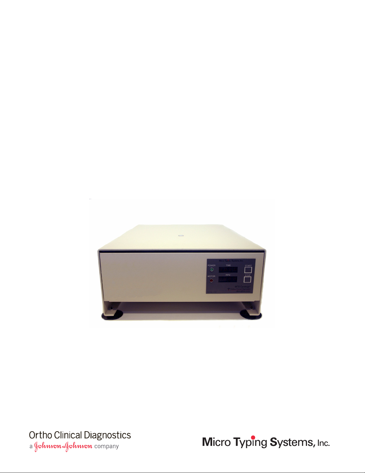
Centrifuge User’s Guide - Model 5150-60
ID-Micro Typing System™
Page 2

Customer Technical Services
Contact OCD Customer Technical Services (CTS) at
1-800-421-3311.
Proprietary Notice
This document discloses subject matter in which Micro Typing
Systems, Inc. (MTS) has certain proprietary rights. Neither receipt
nor possession of this document confers or transfers any rights to
copy, reproduce or disclose the document, any part of such
document or any information contained therein without the
express written consent of a duly authorized representative of
Micro Typing Systems, Inc.
Acknowledgments
ID-MTS is a trademark of Micro Typing Systems, Inc.
ID-Micro Typing System is a trademark of Micro Typing
Systems, Inc.
Windows is a registered trademark of Microsoft Corporation.
Copyright © by Micro Typing Systems, Inc., 2003, 2004, 2008
Pompano Beach, FL 33069
All rights reserved.
ii 2008-10-15
MTS Centrifuge™ User’s Guide
Page 3

MTS Centrifuge™ User’s Guide
This guide describes how to install, use, and maintain the MTS Centrifuge™.
Intended Use
The MTS Centrifuge™ is a precision bench-top, single speed instrument
designed specifically for the ID-MTS™ Gel Test™.
The MTS Centrifuge™ is intended for centrifugation of the ID-MTS™ Gel
Card.
Description
The MTS Centrifuge™ is designed and manufactured to use the principle of
centrifugal force to yield an appropriate cell migration in the microtube of the
ID-MTS™ Gel Card.
The centrifuge is designed with a preset time and speed to ensure consistent
results. The centrifuge time is controlled by a pre-programmed timer that will
apply power to the motor for 10 minutes. This time cannot be changed.
The MTS Centrifuge™ Model 5150-60 will reach a speed of 895 ±25 RPM
(revolutions per minute); 80-90 RCF (Relative Centrifugal Force) and has a
time of 10 minutes. The centrifuge’s rotor head accommodates up to 24
ID-MTS™ Gel Cards.
MTS Centrifuge™ User’s Guide 2008-10-15 3
Page 4

MTS Centrifuge™ User’s Guide
Precautions and Limitations
This guide includes the following topics:
Precautions and Limitations . . . . . . . . . . . . . . . . . . . . . . . . . . . . . . . . . . . . . . 4
Warnings, Cautions, and Symbols . . . . . . . . . . . . . . . . . . . . . . . . . . . . . . . . . 6
Specifications . . . . . . . . . . . . . . . . . . . . . . . . . . . . . . . . . . . . . . . . . . . . . . . . . 8
Unpacking and Installation . . . . . . . . . . . . . . . . . . . . . . . . . . . . . . . . . . . . . . 9
Controls and Indicators . . . . . . . . . . . . . . . . . . . . . . . . . . . . . . . . . . . . . . . . 12
Operation . . . . . . . . . . . . . . . . . . . . . . . . . . . . . . . . . . . . . . . . . . . . . . . . . . . 15
Routine Maintenance . . . . . . . . . . . . . . . . . . . . . . . . . . . . . . . . . . . . . . . . . . 17
Troubleshooting . . . . . . . . . . . . . . . . . . . . . . . . . . . . . . . . . . . . . . . . . . . . . . 20
Schematic Diagram . . . . . . . . . . . . . . . . . . . . . . . . . . . . . . . . . . . . . . . . . . . 21
Revision History . . . . . . . . . . . . . . . . . . . . . . . . . . . . . . . . . . . . . . . . . . . . . 22
Precautions and Limitations
Precautions
The electric plug is 3-prong type for safe grounding. If the wall outlet is
not the grounded type, an approved adapter must be used.
Only authorized service personnel should make repairs and adjustments.
Never attempt to open the drawer while the rotor is spinning; serious
injury may result.
Personal injury and instrument damage is possible if this centrifuge is
operated with a rotor not specified by MTS.
Always position ID-MTS™ Gel Cards to maintain balance in the
centrifuge. The following diagram shows some examples of balanced
arrangements.
4 2008-10-15 MTS Centrifuge™ User’s Guide
Page 5

Figure 1. Examples of balanced ID-MTS™ Gel Card arrangements
Precautions and Limitations
2
643
8
151412109
2016 18
If the power is interrupted, and remains off, the door will not automatically
2221
open. The drawer may be opened using the release safety latch once the
rotor has come to a complete stop.
If power is momentarily interrupted, the timer will reset to zero (a blank
timer display), the tachometer RPM display will show the appropriate
speed during spin down, and the drawer will open automatically when the
rotor head has come to a complete stop.
If you need to leave during the centrifugation process, you may choose to
set a second, independent timer for 10 minutes. If the centrifuge stops and
time remains on the second timer, you will know there has been an
interruption in power.
CAUTION: Incorrect results may occur if the ID-MTS™ Gel Cards are
not centrifuged for the preset time. If the centrifuge is
interrupted, discard the ID-MTS™ Gel Cards and repeat
the tests when you can monitor the centrifuge for the entire
ten minute period.
MTS Centrifuge™ User’s Guide 2008-10-15 5
Page 6

MTS Centrifuge™ User’s Guide
Warnings, Cautions, and Symbols
Limitations
The centrifuge cannot be started until the drawer is closed and latched.
The centrifuge cannot be started while the rotor is in motion.
If the rotor spins slightly when closing the drawer, wait 1 to 2 seconds
before pressing the Start button to ensure the rotor head has stopped
moving.
Do not press the Start button while the centrifuge drawer is open. If the
Start button is pressed with the drawer open, the timer will display 10:00
and may start to count down if the rotor is put in motion (spun).
To reset the timer to 10:00 with the drawer still open, press the Start button
a second time.
To clear the timer with the drawer still open, press the Stop button twice.
ID-MTS™ Gel Cards placed incorrectly in the card holders of the rotor
head can give incorrect results. Always verify ID-MTS™ Gel Cards are
seated firmly in the card holders.
Warnings, Cautions, and Symbols
Warnings
To avoid the risk of electric shock, read all instructions before plugging in
the centrifuge.
To reduce the risk of electric shock, do not remove the Electronics Cover
or Back Panel.
To prevent fire or shock hazards, do not expose this product to water or
moisture.
Only trained personnel should complete the installation procedures. Do
not attempt to operate this centrifuge before thoroughly reading the
instructions in the following topics beginning on page 9: “Unpacking and
Installation”, “Controls and Indicators”, and “Operation”.
Never perform the safety interlock release procedure when the rotor is still
turning. Opening the drawer will expose rotating parts; serious injury may
result.
6 2008-10-15 MTS Centrifuge™ User’s Guide
Page 7

Warnings, Cautions, and Symbols
Do not bypass the drawer safety interlock as a routine operation; serious
injury may result.
Electrical grounding of the MTS Centrifuge™ is accomplished with the
three-prong plug included with the instrument. If the intended wall outlet
is a grounded (three wire) type, the instrument will be grounded
automatically.
If the intended wall outlet is not the grounded type, use an approved
adapter. Make sure the grounding lead on the adapter is firmly attached
to a grounded receptacle box before operating the instrument.
Extension cords should also be three-wire type.
NEVER attempt to open the drawer while rotor is spinning.
Personal injury and instrument damage is possible if this centrifuge is
operated with a rotor not specified by MTS.
Cautions
If you hear excessive or loud banging sounds, press the Stop button
immediately. The centrifuge will spin down for two minutes and then
release the latch. Open the drawer carefully and inspect for problems.
Note: A slight rattle or squeak may be heard during the first minute of
each cycle.
Always balance the ID-MTS™ Gel Cards in the rotor head before closing
the drawer for a run.
Do not attempt to override the latch release by turning the power switch
off and on. This could cause damage to the electronics of the instrument.
Symbols
These symbols are located on back panel and inside of the electronics
compartment.
The Caution symbol indicates a possible hazardous
situation. Non-compliance with this instruction may lead to
minor physical injury or damage to property.
Inside the centrifuge, the Caution symbol indicates the
Safety Latch Interlock Release mechanism. Use the safety
latch only during an electrical power failure or servicing.
The Ground symbol identifies any terminal connected to a
protective earth ground.
MTS Centrifuge™ User’s Guide 2008-10-15 7
Page 8

MTS Centrifuge™ User’s Guide
Specifications
Specifications
The centrifuge time is controlled by a pre-programmed timer that applies
power to the motor for 10 minutes. Time and speed are pre-set at the factory
and cannot be changed.
Instrument size and weight
Height 5.75 in (14.37 cm)
Width 13.50 in (33.75 cm)
Depth 19.25 in (48.12 cm)
Weight 14.00 lb (6.36 Kg)
Electrical requirements for Model 5150-60
Voltage 110-120 VAC
CAUTION: The main supply voltage should
not exceed ±10% of the nominal
voltage.
Frequency 60 Hz
Power 110 VA
Amps 3.0
Environmental Conditions
Temperature
(operating)
5-40° C
Performance
Rotor Head The rotor head accommodates up to 24
ID-MTS™ Gel Cards.
Speed/Time 895 RPM ±25 (80-90 RCF) for
10:00 minutes ±10 seconds
8 2008-10-15 MTS Centrifuge™ User’s Guide
Page 9

Unpacking and Installation
Unpacking
The MTS Centrifuge™ has been carefully packed to prevent shipping
damage. Inspect the carton and contents for damage.
Note: If damaged, file a claim with the delivering carrier and notify
Unpacking and Installation
OCD Customer Technical Service immediately.
Unpacking the Centrifuge
Remove the rotor head box from the centrifuge box. Carefully open
1
the rotor head box and remove the rotor head.
Remove the power cord and place it next to the rotor head on the
2
table.
Remove the top foam insert from the box.
3
Remove the centrifuge from the box and place it on the table next to
4
the rotor head and power cord (do not install the rotor head).
Check that all items have been received.
5
Item
MTS Centrifuge™ 1
Rotor Head 1
Power Cord 1
MTS5150-60 Belt/Fuse Spares Kit 1
6
Certificate of Conformity 1
Inspect all items. If any items are missing or damaged, contact OCD
Customer Technical Services.
Qty
MTS Centrifuge™ User’s Guide 2008-10-15 9
Page 10

MTS Centrifuge™ User’s Guide
Unpacking and Installation
Installation
Installing the Centrifuge
Place the MTS Centrifuge™ on a sturdy and level surface in the
1
designated work area. The surface of the bench or table should be
clean and dry.
CAUTION: Do not plug the centrifuge in at this time. The
Turn the MTS Centrifuge™ over so that the centrifuge lies on its
2
cover and the rubber feet are facing up.
Locate the two shipping support braces that run across the bottom of
3
the cover.
Locate the two inner screws on each brace that attach the centrifuge
4
drawer to the braces; black rubber washers are located between the
braces and the centrifuge drawer.
drawer of the MTS Centrifuge™ is secured to two
shipping bars for reinforcement during shipping.
Remove the four screws with a screwdriver. Remove the black
5
rubber washers. (Do not remove the four outer screws that are
secured to the cover.)
Turn the centrifuge back on its rubber feet, being careful not to let
6
the drawer abruptly open.
Open the drawer and place the rotor head onto the spindle.
7
WARNING: Never open the drawer when the rotor is still
turning. Rotating parts would be exposed; serious
injury may result.
Note: If the drawer is latched, open the drawer by using the
safety latch interlock release. Locate the small lever
inside the latch release access located on the rear panel,
and use a screwdriver to slide the release lever to the left
until the latch is released. See Figure 2.
10 2008-10-15 MTS Centrifuge™ User’s Guide
Page 11

Installing the Centrifuge (continued)
Unpacking and Installation
Figure 2. Rear Panel
Latch Release
Plug one end of the power cord into the power cord connector on the
8
back panel of the centrifuge and plug the other end into a
grounded AC outlet that has the appropriate voltage and frequency.
Power line voltage and frequency requirements are shown on the
back panel of the centrifuge.
WARNING: Electrical grounding of the MTS Centrifuge™ is
Power Switch
3 Amp Fuse Holder
accomplished with the three-prong plug included
with the instrument.
Power Cord Connector
Instrument Label
If the intended wall outlet is a grounded (three
wire) type, the instrument will be grounded
automatically. If the intended wall outlet is not the
grounded type, an approved adapter should be
used.
Make sure the grounding lead on the adapter is
firmly attached to a grounded receptacle box
before operating the instrument. Extension cords
should also be three wire type.
CAUTION: Do not attempt to operate this centrifuge before thoroughly
reading and understanding the “Operation” section on
page 15.
MTS Centrifuge™ User’s Guide 2008-10-15 11
Page 12

MTS Centrifuge™ User’s Guide
Controls and Indicators
Controls and Indicators
Figure 3. Front Panel
Time Display Start Button
Power Indicator
Motor Indicator
Controls
Control Description
Power Switch
The power switch is located on the left-hand side of the
back panel (refer to Figure 2 on page 11). The power
switch controls all power to the system. It is mounted
through a cutout in the back panel. The cover latch
releases after a 2 to 3-second delay when the power
switch is turned on.
Stop ButtonTachometer RPM Display
12 2008-10-15 MTS Centrifuge™ User’s Guide
Page 13

Refer to Figure 3 on page 12.
Control Description
Controls and Indicators
Start Button
Stop Button
The start button is located on the front right hand side of
the centrifuge. Press this button to start the centrifugation
cycle.
Note: The centrifuge will not spin if the drawer is not
latched.
CAUTION: Do not press the Start button while the
centrifuge drawer is open.
If the start button is pressed while the centrifuge drawer
is open, the time display will read 10:00, and will begin
to count down if the rotor head is then put into motion. If
this occurs, reset the time display to 10:00 by pressing
the start button a second time, or clear the time display
by pressing the stop button twice.
The stop button is located on the front right hand side of
the centrifuge. Press the stop button when you need to
remove power from the motor immediately.
If the centrifuge is in mid-cycle when the stop button
is pressed, the latch releases when the rotor has
stopped spinning.
CAUTION: Incorrect results may occur if the
ID-MTS™ Gel Cards are not
centrifuged for the preset time. If the
centrifuge is interrupted, discard the
ID-MTS™ Gel Cards and repeat the
tests when you can monitor the
centrifuge for the entire ten minute
period.
If the centrifuge is idle when the Stop button is
pressed, the latch releases after a 2 to 3-second delay.
MTS Centrifuge™ User’s Guide 2008-10-15 13
Page 14

MTS Centrifuge™ User’s Guide
Controls and Indicators
Indicators
Refer to Figure 3 on page 12.
Indicators Description
Power Indicator
Motor Indicator
Time Display
Tachometer (RPM)
Display
The green power indicator is located on the front right
hand side of the centrifuge. When illuminated, it
indicates that the instrument is plugged into a power
receptacle and that the power switch is in the ON
position.
The red motor indicator is located on the front right hand
side of the centrifuge. When illuminated, it indicates that
power is being supplied to the motor. However, if the
centrifuge drawer is not firmly latched, the motor will
not spin.
The time display is located on the front right hand side of
the centrifuge. The same four-digit time display is used
in digital clocks.
Time is displayed in minutes and seconds from 10:00.
Characters illuminate and are approximately 0.5" in
height. The display is blank when 00:00 is reached.
With the centrifuge drawer latched, the time begins
when the Start button is pressed and counts down to
zero while the centrifuge is running.
The tachometer (RPM) display is located on the front
right-hand side of the centrifuge and is the lower of the
two visible displays.
Speed is displayed in RPMs, 1 to 9999.
Characters illuminate and are approximately 0.5" in
height. The display is blank when the rotor head
speed is zero.
The tachometer will remain operational as long as the
power switch is in the ON position.
14 2008-10-15 MTS Centrifuge™ User’s Guide
Page 15

Operation
Operating the MTS Centrifuge™
Turn the power switch to the ON position (see Figure 2 on page 11).
1
The drawer will open after a 2 to 3-second delay.
Check the centrifuge drawer for any foreign objects and lift the
2
rotor, if necessary, to remove them. When replacing the rotor, make
sure it is securely seated on the spindle.
Carefully insert the ID-MTS™ Gel Cards to be tested into the card
3
holders. Be sure each ID-MTS™ Gel Card is seated completely in
the holder.
CAUTION: Always balance the ID-MTS™ Gel Cards before
closing the drawer (see Figure 1 on page 5).
Operation
Close the centrifuge drawer and make sure the drawer is latched
4
(listen for a click).
MTS Centrifuge™ User’s Guide 2008-10-15 15
Page 16

MTS Centrifuge™ User’s Guide
Operation
Operating the MTS Centrifuge™ (continued)
Press the start button to activate the timer and start the motor.
5
Note: The start button will not activate the timer while the rotor
head is in motion. If the tachometer RPM display
indicates that the rotor is turning, wait until the display
indicates no movement (blank display) before pressing
the Start button.
If you need to leave during the centrifugation process, you may
choose to set a second, independent timer for 10 minutes. If the
centrifuge stops and time remains on the second timer, you will
know there has been an interruption in power.
WARNING: NEVER attempt to open the drawer while rotor is
spinning.
CAUTION: Incorrect results may occur if the gel cards are not
centrifuged for the preset time. If the centrifuge is
interrupted, discard the gel cards and repeat the
tests when you can monitor the centrifuge for the
entire ten minute period.
CAUTION: If you hear excessive or loud banging sounds, press
the stop button immediately. The centrifuge will
spin down for two minutes and then release the
latch. Open the drawer carefully and inspect for
problems.
Note: A slight rattle or squeak may be heard during the first
minute of each cycle.
When the cycle is completed, the latch releases after the rotor stops
spinning.
Open the drawer, remove the gel cards, and read the results.
6
16 2008-10-15 MTS Centrifuge™ User’s Guide
Page 17

Routine Maintenance
Perform routine maintenance procedures when recommended.
Routine Maintenance
Perform Procedure
Daily “Confirm Instrument Displays” on
page 17
Ye ar l y “Inspect the Retractile Cable Sub-
Assembly” on page 18
“Inspect the Drive Belt” on page 19
As Needed “Check the Rotor Head Speed” on page 19
Clean as Needed, at Routine QC
Intervals, and after Repairs
Note: Only authorized service personnel should perform major repair and
adjustments.
“Clean the Instrument” on page 19
Daily
Confirm Instrument Displays
Check that the tachometer RPM display reads 895 ±25.
1
Check that the timer display begins at 10:00 minutes and counts
2
down (9:59, 9:58, etc.). When the timer reaches zero, the display
becomes blank.
Contact OCD Customer Technical Services if a display is not
3
functioning correctly.
MTS Centrifuge™ User’s Guide 2008-10-15 17
Page 18

MTS Centrifuge™ User’s Guide
Routine Maintenance
Yearly
Inspect the Retractile Cable Sub-Assembly and the Drive Belt for wear.
Inspect the Retractile Cable Sub-Assembly
Remove the rotor head from the centrifuge.
1
Turn off the power to the centrifuge. Be sure to leave the centrifuge
2
drawer unlatched.
Unplug the power cord from the rear of the instrument and the
3
power supply.
WARNING: Electric shock hazard. Serious injury may occur if
the power cord is not unplugged.
Turn the instrument upside down, and extend the drawer out in order
4
to see the black Retractile Cable Sub-Assembly extended from the
rear of the instrument to the inside of the drawer.
Check the Retractile Cable Sub-Assembly for the following:
5
Are there any nicks, cuts, or tears visible in the outer black
surface of the Retractile Cable exposing
black wires on the inside of the Retractile Cable Sub-Assembly?
Has the Retractile Cable lost its coil?
Have any of the green, white, or black wires that extend out from
each side of the Retractile Cable Sub-Assembly been nicked or
cut to the point where the metal wire inside is exposed?
Replace the Retractile Cable Sub-Assembly if any items listed in
6
step 5 are observed. Contact OCD Customer Technical Services for
an MTS 5150-60 Retractile Cable Replacement Kit.
Note: Black marks on the inside surfaces and/or black dust
particles found inside the electronic housing is normal and
expected. The Retractile Cable’s thick black insulation is
designed to protect the green, white, and black wires that are
inside. Replace the Retractile Cable only if the green, white,
or black wires on the inside of the Retractile Cable are
exposed.
the green, white, or
18 2008-10-15 MTS Centrifuge™ User’s Guide
Page 19

Routine Maintenance
Inspect the Drive Belt
Follow the instructions on the insert in the Belt/Fuse Spares kit to
1
access the Drive Belt.
Check the Drive Belt for nicks, tears, or areas that appear to be
2
stretched thin.
Replace the Drive Belt if any items in step 2 are observed.
3
As Needed
The MTS Centrifuge™ is fully calibrated at the factory. Additional
calibration is not necessary. However, motor speed can be checked, if needed.
Note: A tachometer window on the top of the centrifuge has been provided
for verification purposes. If necessary, the plastic plug may be
removed by pressing up from the inside. Always replace the plug
before resuming normal operation.
Check the Rotor Head Speed
Use an optically activated tachometer to measure the speed of the
1
rotor head. (Use of a mechanical tachometer that physically contacts
the centrifuge rotor head or shaft may slow the speed of the
centrifuge and give incorrect results.)
Acceptable speed range: 895 ±25 RPM
Note: The speed of the rotor head cannot be adjusted.
Contact OCD Customer Technical Services if the speed of the rotor
2
head is not within the specified range.
Clean as Needed, at Routine QC Intervals, and after Repairs
Clean the Instrument
Clean the MTS Centrifuge™ with a lint-free cloth and a mild
1
detergent or 70% isopropyl alcohol.
MTS Centrifuge™ User’s Guide 2008-10-15 19
Page 20

MTS Centrifuge™ User’s Guide
Troubleshooting
Troubleshooting
Circumstance Action
Centrifuge will not run Check that the power cord is connected to the
instrument and to a live power source, and that the
instrument is turned on.
Check that the fuse has not blown.
Be sure the drawer is firmly closed and latched.
Wait 1 to 2 seconds for the rotor to stop moving and
press the Start button.
Loud banging noise is heard during spin Check that gel cards are properly positioned to balance the
rotor (see Figure 1 on page 5).
The negative cell buttons are not level
Anomalous results (e.g., a known negative
sample appears positive or inconclusive)
Power interruption:
If the power is interrupted and remains off,
the door will not automatically open. Once
the rotor comes to a complete stop, open the
drawer using the release safety latch.
If power is momentarily interrupted, the time
display resets to zero (blank display), the
tachometer RPM display shows the
appropriate speed during spin down, and the
latch automatically releases when the rotor
head has come to a complete stop.
Timer Display shows a time other than ten
minutes (10:00) upon initialization of the
centrifuge.
Check for proper placement of gel cards in the gel card
holders.
Check that no obstructions, such as dirt or pieces of foil
from a partially opened gel card, are preventing the rotor
card holders from swinging to a full 90 degree angle
during centrifugation.
Check that the centrifuge has spun for the entire preset time
of 10 minutes.
CAUTION: Incorrect results may occur if the gel cards
are not centrifuged for the preset time. If
the centrifuge is interrupted, discard the
gel cards and repeat the tests when you
can monitor the centrifuge for the entire
ten minute period.
Do not use the centrifuge for testing.
Shut off the instrument and disconnect the power cord
from the instrument and the power supply.
Contact OCD Customer Technical Services.
If a problem persists, shut off the instrument, disconnect the power cord from
the instrument and the power supply, and contact OCD Customer Technical
Services, 1-800-421-3311.
20 2008-10-15 MTS Centrifuge™ User’s Guide
Page 21

Schematic Diagram
Schematic Diagram
Figure 4. MTS Centrifuge™ schematic
MTS Centrifuge™ User’s Guide 2008-10-15 21
Page 22

MTS Centrifuge™ User’s Guide
Revision History
Revision History
October 2008
Revision to Chapter/Section/Topic/Appendix Page Description
Entire manual All Updated product references.
Reworded statements for greater clarity.
Covers
Precautions and Limitations 5
Installing the Centrifuge 10
Operating the MTS Centrifuge™ 15
Troubleshooting 20
Applied new branding. Replaced photo of
workstation with photo of centrifuge.
Replaced diagram of balanced gel card
arrangements.
Modified procedure to clarify use of safety
latch interlock release.
Reworded instructions for inspecting the
centrifuge before use.
Expanded causes of centrifuge failing to run:
power source not “live”; unit not turned on;
blown fuse.
Added reason for “negative cell buttons not
level”: obstruction preventing card holders
from swinging to full 90 degree angle.
Added statement that instrument should not
be used if timer display shows any value other
than 10:00 minutes upon initialization.
June 2004
Revision to Chapter/Section/Topic/Appendix Page Description
Entire manual All Changed the part number of the guide to the
product code 6902118.
Changed Customer Technical Support at 800-
398-7317 to OCD Customer Technical
Services at 1-800-421-3311.
Changed the page layout.
Reorganized information.
Edited the text for clarity and conciseness.
Designed a new cover for the guide.
Added the date in the footer.
Added the Revision History.
Specifications 8
Unpacking and Installation 9
22 2008-10-15 MTS Centrifuge™ User’s Guide
Added Performance
Added Certificate of Conformity to the list of
items receieved.
Page 23

Revision History
June 2004 (continued)
Revision to Chapter/Section/Topic/Appendix Page Description
Routine Maintenance 19 Added “Clean as Needed, at Routine QC
Intervals, and after Repairs”
Removed instructions to simultaneously
compare the Tachometer Display to a
tachometer reading and to use a stop watch to
validate the Timer Display.
MTS Centrifuge™ User’s Guide 2008-10-15 23
Page 24

Ortho-Clinical Diagnostics, Inc.
1001 US Hwy 202
Raritan, NJ 08869-0606
Micro Typing Systems, Inc.
1295 SW 29th Avenue
Pompano Beach, FL 33069-4359
Pub. No: 6902118 (EN)
© Ortho-Clinical Diagnostics, Inc. 2008
© Micro Typing Systems, Inc. 2008
 Loading...