

Page 1
JLFSMFC 601
Multifunction Cooker
Instruction manual
Page 2

Important safety information
It is most important that this instruction book should be retained with the appliance for future reference. Should the
appliance be sold or transferred to another owner, or should you move house and leave the appliance, always ensure
that the book is supplied with the appliance in order that the new owner can get to know the functioning of the
appliance and the relevant warnings. These warnings have been provided in the interest of safety. You MUST read
them carefully before installing or using the appliance.If you are unsure of the meanings of the these warnings contact the John Lewis branch from which you purchased the appliance.
Installation
• This cooker must be installed by qualified and compe-
tent personnel to the relevant National Standards.
• Refer to the installation information in chapter „Installation‰.
• This cooker is heavy. Take care when moving it.
• Do not use the oven door handle for lifting or moving
the cooker, or for removing the appliance from the
packaging.
• This cooker must be installed in an adequately ventilated room.
• The technical data is indicated on the rating plate located on the back of the appliance. This plate must not be
removed.
• The adjustment conditions are shown on a label applied
to the packaging and the appliance.
• Remove all packaging, both inside and outside the hob,
before using the cooker.
• Before assembling the cooker remove all the parts that
are not firmly attached to it, in particular the pan supports and burners. To lighten the weight of the cooker,
the accessories inside the ovens may also be removed,
preventing accidental damage during the overturning
process.
• If the cooker is set on a pedestal, appropriate measures
must be taken to prevent it from sliding off the pedestal.
• Additions or modifications to the appliance are not
permitted.
• Repairs to the cooker must only be carried out by trained registered service engineers.
Child safety
• The cooker is designed to be operated by adults. Do not
allow children to tamper with the controls or play with
near the cooker.
• Do not allow children to sit or climb on the drop down
doors.
• Never store items that children may attempt to reach
above the appliance.
• Whenever the cooker is in use and in the necessary
cooling down period, take care to position the saucepans
in a way to prevent burns or overturning. Avoid leaving
the oven door open during use and immediately after
cooking, the heating elements will still be hot.
• Only allow older children to use the cooker with adult
supervision.
Use
• This cooker is intended for domestic cooking only. It is
not designed for commercial or industrial purposes.
• Remove all stickers and film from the glass doors and
the stainless steel cabinet.
• Cookers become very hot with use, and retain their
heat for long periods after use. Care should be taken to
avoid touching the hob area and the inside of the oven
until fully cooled.
• There is the risk of burns from the appliance if used
carelessly.
• Cables from other electrical appliances must not touch the hot surface of the appliance or hot cookware.
• Overheated fat and oil can ignite quickly. When cooking with fat or oil (e.g. frying chips) do not leave the
appliance unattended.
• Do not leave cookware containing foodstuffs, e.g. fat
or oil in or on the oven or on the hob in case they are
inadvertently switched ON.
• Ensure that you switch the gas hobs and ovens OFF
after use.
• Do not ignite a gas hob without a saucepan over the
burner.
• When in use the gas hob will produce heat and moisture in the room in which it has been installed. Ensure
there is a continuous air supply, keeping air vents in
good condition or installing a cooker hood with a vented outlet.
• When using the hob for a long period of time, opening
a window or increasing the extractor speed should improve the ventilation.
• All the cookerÊs vents must be free of obstructed to
ensure ventilation of the oven cavity.
• Do not use the cooker if it is in contact with water.
• Do not operate the cooker with wet hands.
• Always stand back from the cooker when opening the
oven doors during cooking or at the end of it, to allow
any build up of steam or heat to release.
• Unstable or misshapen pans should not be used on the
hob as they can cause an accident by tipping or spillage.
• Always support the grill pan when it is in the
withdrawn or partially withdrawn position.
• The cooker must not be used as a work surface or as a
storage surface.
• Never line any part of the oven with aluminium foil.
• Do not allow heatproof cooking materials, e.g. roasting bags, to come into contact with the oven elements.
2
Page 3

• Do not place or store sealed cans, aerosols, flammable liquids, highly inflammable materials or fusible
objects (e.g. plastics film, plastic, aluminium) inside,
on, above or near the cooker.
• Do not hang towels, dishcloths or clothes from the
oven or its handles.
• Always use oven gloves to remove and replace food
in the oven.
Maintenance and cleaning
• For hygiene and safety reasons this cooker should
be kept clean at all times. A build-up of fats or other
foodstuffs could result in a fire especially in the grill
pan.
• Always allow the cooker to cool down and ensure it
is switched of at the wall switch prior to carrying out
any cleaning / maintenance work.
• Only clean the cooker in accordance with the instructions contained within this manual.
• For cleaning or for maintenance work, the electrical
supply to the appliance must be switched off and the
appliance must be cooled down.
• For safety reasons, the cleaning of the cooker with
steam jet or high-pressure cleaning equipment is not
permitted.
Service
• Before leaving the factory, this cooker has been
tested and set up by qualified, specialist personnel,
to guarantee the best operating results. Each repair
or adjustment that may subsequently be necessary
must be carried out with the utmost care and attention. Therefore this cooker should only be repaired or
serviced by an authorised service engineer and only
genuine approved spare parts should be used.
Environmental information
• After installation, please dispose of the packaging
with due regard to safety and the environment.
• When disposing of an old appliance, make it unusable, by cutting off the cable and make safe any
components, which might be dangerous for children
(remove doors etc.).
• The Symbol
on the product or on its packaging
indicates that this product may not be treated as
household waste. Instead it should be taken to the
appropriate collection point for recycling of electrical
and electronic equipment. By ensuring this product
is disposed of correctly, you will help prevent potential negative consequences for the environment and
human health, which could otherwise be caused by
inappropriate waste handling of this product. For
more detailed information about recycling of this
product, please contact your local council, your household waste disposal service or the shop where you
purchased the product.
3
Page 4
Contents
4
Important safety information 2
Description of the appliance 5
Installation 6
Technical specifications 6
Electrical connection 7
Gas connection 8
Stability chain 9
Description of the hob 10
Assembly 10
• Fitting the adjustable feet 10
• Levelling the cooker 10
The control panel 11
• Despription of hob burner 11
• Layout of burner - Description of symbols 11
• Description of electric oven knob 11
Conversion from natural gas to LPG 12
Using the hob 13
• Switching on the burners 13
• One touch ignition and safety valve 13
• Manual ignition 13
• Switching off the burners 13
• Suggestions for using the hob burners correctly 13
Using the ovens 14
Multifunction oven (Bottom oven) 14
Electronic programmer 15
• Setting the clock for first time 15
• How to change the time 15
• Minute timer function 15
• End cook function 15
• Programmable timer function 15
Conventional oven (Top oven) 16
Maintenance and cleaning 18
• Cleaning the stainless steel 18
• Cleaning enamelled surfaces 18
• Cleaning the knobs and the control panel 18
• Cleaning the pan supports and burners 18
• Cleaning the igniter plugs and thermocouples 18
• Cleaning the oven 19
• Cleaning the oven walls 19
• Cleaning the door 19
• Replacing the light bulb 19
Special maintenance 20
• Removing the shelf runner grid 20
Something not working 21
Repairs - after sales service 22
• Spare parts 22
Guide to using the instruction manual
The following symbols will be found in the text to guide
you throughout the instructions:
Safety instructions
Hints and tips
Environmental information
This appliance complies with the following
E.E.C. Directives:
• 73/23/EEC (Low voltage directive) and
subsequent modifications.
• 89/336/EEC (Electromagnetic disturbance
directive) and subsequent modifications.
• 90/396/EEC (Gas appliances directive) and
subsequent modifications.
•89/109/EEC (Material in contact with food
directive) and subsequent modifications.
Page 5
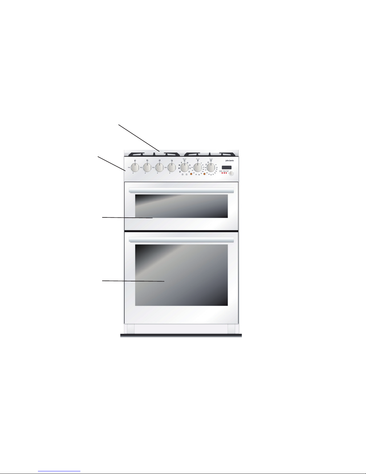
Description of the appliance
1
2
3
4
1 Hob
2 Control panel
3 Conventional top oven
4 Multifunction main oven
5
Page 6
Installation
It is dangerous to alter the specifications or attempt to modify this product in any way.
Care must be taken to ensure that the appliance does not stand on the electrical supply cable
(not supplied).
Any electrical work required to install this appliance should be carried out by a qualified
electrician or competent person.
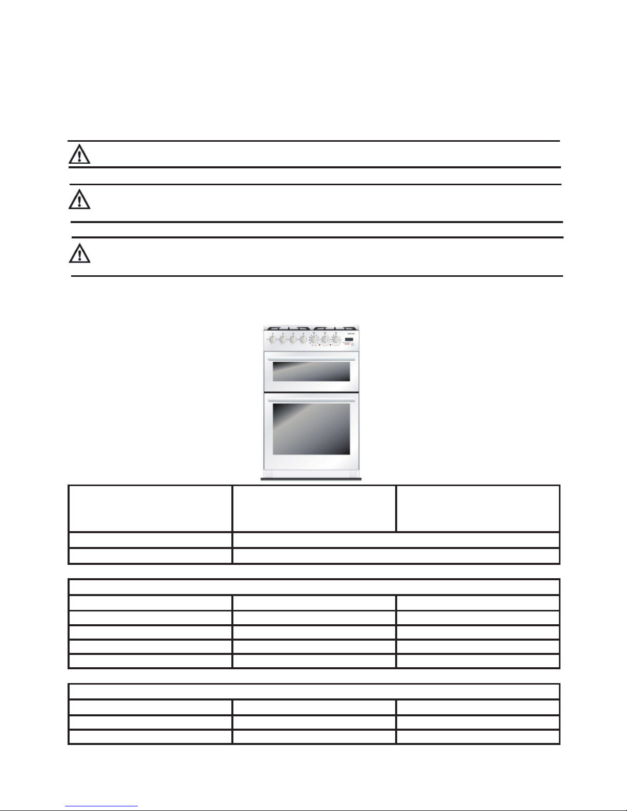
Appliance dimensions
Width
60 cm
Depth
60 cm
Height
85-90.5 cm
Connection voltage 230 V ~ 50 Hz
Maximum connection load 4.78 kW
Gas Hobs
Position Type Power
Rear Left Simmer 1 kW
Rear Right Rapid 3 kW
Front Left Triple Ring 3.9 kW
Front Right Semi-Rapid 1.75 kW
Electric Ovens
Position Type Power
Top Conventional 2.18 kW
Bottom Multifunction 2.60 kW
Technical specifications
6
Page 7
Electrical connection
The electrical connection should be made using a double pole isolating switch (cooker socket) with at least
3mm contact separation in all poles. The cable must
have conductors of sufficiently high cross-sectional area
to prevent overheating and deterioration.
We recommend you use a new length of 2,5 mm2 twin
core and earthed cable to ensure your safety.
Make the connection as shown in figure by proceeding
as follows:
Preform wires to the appropriate shape to suit fitting
into the mains terminal block.
Strip inner insulation on wires using wire strippers.
Ensure all screws are securely tightened.
Clamp the mains cable securely ensuring 5mm of the
outer insulation is inside the terminal block and that
the wires are not taut but not so slack as to cause any
fouling.
Connect the remaining end of the mains cable to the
appliance to the appliance point / junction box.
Place fuse / miniature circuit breaker in circuit and
switch on at mains.
When refitting the mains terminal cover, ensure that
the lower tabs are located inside the bottom edge of
the aperture, before fixing the two screws into the top
edge of the mains terminal cover. Ensure that the cover
is securely fastened.
•
•
•
•
•
•
•
•
•
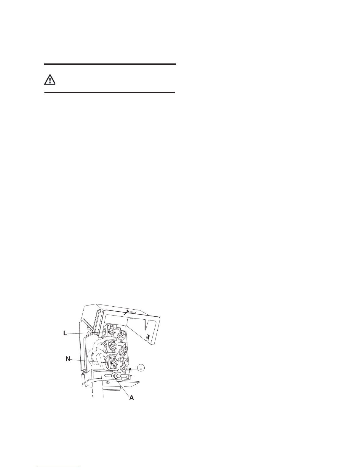
WARNING: This appliance must be earthed. Do
not earth this appliance to the gas supply piping.
Connect to 230 - 240V AC supply only.
Proceed as follows:
• Open the terminal board box, unscrew the screw A
that locks the cable;
• Loosen the screw contacts and replace the cable
with one of the same length that corresponds to the
specifications in the table in section „Electric power
cable section‰;
• The „yellow-green‰ earth wire must be connected
to the terminal and must be approximately 20 mm
longer than the line cables;
• The neutral „blue‰ wire must be connected to the
terminal marked with the letter N;
• The line wire „brown‰ must be connected to the
terminal marked with the letter L.
7
Page 8
Gas connection
The room containing the appliance should have an air
supply in accordance with B.S. 5440 part 2.
1. All rooms require an opening window or equivalent,
and some rooms will require a permanent vent as well.
2. For room volumes up to 5m³ an air vent of 100cm² is
required.
3. If the room has a door that opens directly to the
outside, and the room exceeds 1m³ no air vent is required.
4. For room volumes between 5m³ and 10m³ an air
vent of 50cm² is required.
5. If there are other fuel burning appliances in the
same room B.S. 5440 part 2 should be consulted to
determine the air vent requirements.
6. The appliance must not be installed in a bed sitting
room of less than 20m or in a bathroom or shower
room.
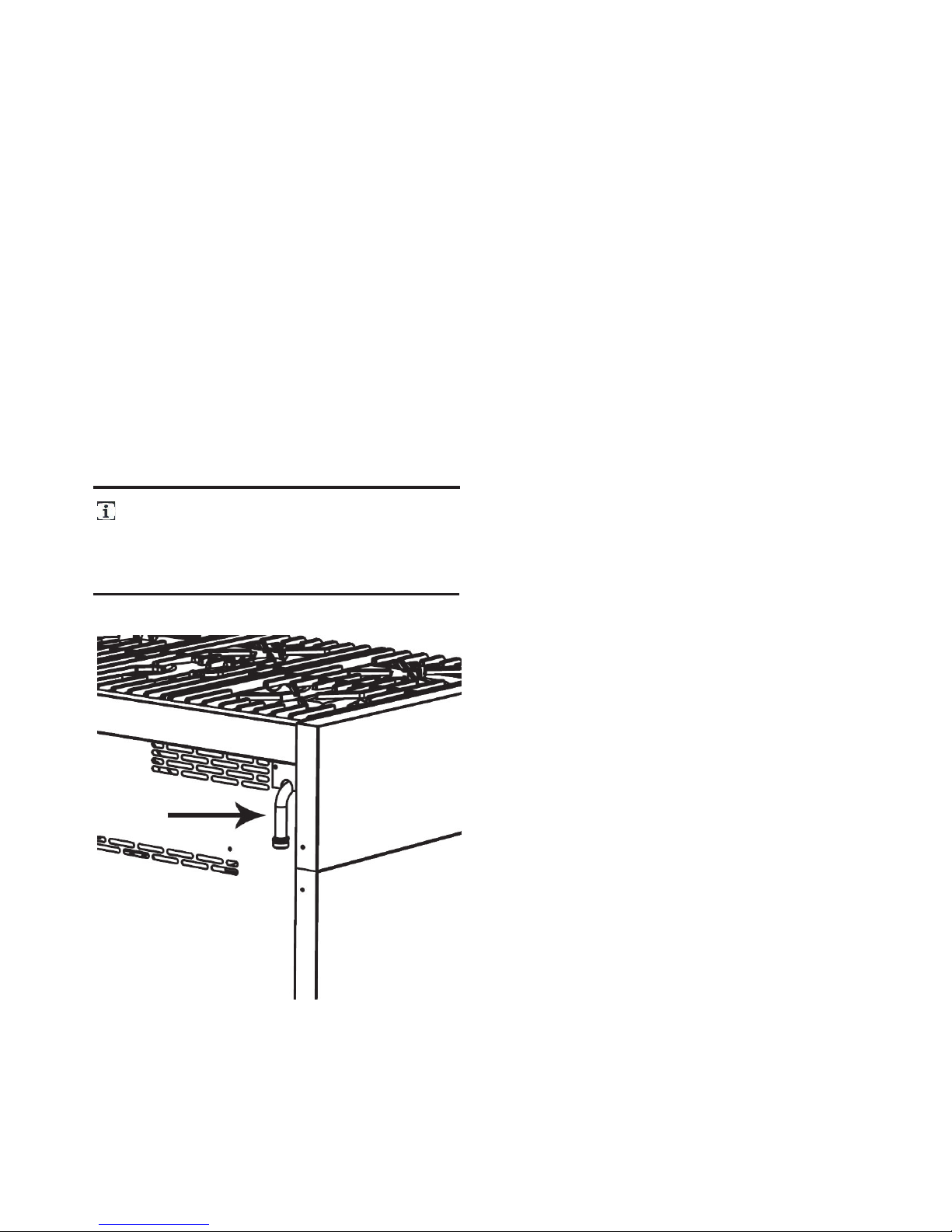
We recommend checking that the appliance is
properly set up for the type of gas distributed. The
threaded ½‰ gas connection pipe is located at the
rear on the right hand side of the appliance.
The cooker is designed to match the depth of standard
600mm worktops. An adaptor back plate should, therefore, be fitted within the shaded area shown to allow
the cooker to be pushed in fully and chased to the
wall.Connection to the cooker should be made with
an approved appliance flexible connection to BS 669.
A length of 0.9 to 1.25m is recommended. The length
of hose chosen should be such that when the cooker is
in situ, the hose does not touch the floor.The temperature rise of areas at the rear of the cooker that are
likely to come in contact with the flexible hose do not
exceed 70°C.
8
Page 9

Stability chain
The cooker is fitted with a stability device such as
a proprietary stability chain as shown and firmly
secured to the fabric of the building.Whatever the
position, remember to leave enough room for the
cooker to be pulled out for cleaning and service.
The wall behind the cooker between the hotplate and 450mm above, and across the width of the
cooker, must be an incombustible material such as
ceramic wall tiles.This appliance is designed not to
project in front of standard 600mm worktops (excluding handles). To achieve the best fit the cooker must
be pushed against the wall.
As this appliance is very heavy it should
be situated on a suitably hard surface to
ensure servicing and installation is made
possible with minimal impact on the floor
surface.
9
Page 10

Description of the hob
A Triple ring burner 3.90 kW
B Simmer burner 1.00 kW
C Semi-rapid burner 1.75 kW
D Rapid burner 3.00 kW
Assembly
The cooker is delivered with the feet removed. Before
moving and connecting up the cooker, take the feet
from the packaging and screw them onto the cooker.
This can be done in one of two ways:
A Lifting the cooker off the floor.
B Laying the cooker on its back.
Before assembling the cooker remove all
the parts that are not firmly attached to
it, in particular the pan supports and burners. To lighten the weight of the cooker,
the accessories inside the ovens may also
be removed, preventing accidental damage
during the overturning process.
Fitting the adjustable feet
Should it be necessary to move the cooker,
screw the feet in completely and carry out
the final levelling adjustment only when the
gas and electrical connections have been
made.
Levelling the cooker
After connecting the cooker to the gas and electricity
supply, level the cooker to the floor using the adjustable
feet previously fitted onto the bottom of the cooker.
Should it be necessary to move the cooker,
screw the feet in completely and carry out
the final adjustments only when the other
operations are completed.
10
Page 11

The control panel
The control panel
All the commands and controls for cooking with
the hob and ovens are on the control panel.
Description of hob burner knob
The flame is lit by simultaneously pressing and
turning the knob anticlockwise to the low flame
symbol .To regulate the flow of the flame, turn
the knob to between the maximum and minimum settings. Turn off the burner by returning
the knob to position .
Layout of burner - Description of
symbols
REAR LEFT
FRONT LEFT
REAR RIGHT
FRONT RIGHT
Description of electric oven knobs
The main oven is controlled by two knobs: function
switch knob and thermostat knob. They allow you to
choose the most suitable type of heating for different cooking requirements, by switching on the heating elements appropriately and setting the required
temperature (from 50°C to 260 C).
11
The two orange lights indicate when the preset
temperature has been reached. The orange light
switches on and off to indicate when the heating
automatically kicks in to maintain the temperature
inside the oven at the level set on the thermostat
knob.The oven has an internal light. The light is
always on while the oven is working: it can be
switched on while the oven is off, for cleaning purposes, by turning the function switch knob to the
symbol
Page 12

Conversion from natural gas to LPG
Unscrew the adjustment screw Z to increase the flow, or tighten it to reduce the flow.
The adjustment is correct when the low
flame measures approximately 3 or 4 mm.
When changing quickly from maximum to
minimum flow and vice versa make sure
that the flame does not go out.
It is important to note that this model is designed
for use with natural gas but can be converted for
use with butane or propane gas (conversion kit
included) providing the correct injectors are fitted.
The gas rate is adjusted to suit.
Proceed as follows:
• Remove the pan supports;
• Remove the burners and burner caps (Fig. A);
• Take out the injector (Fig. B) and replace it with
one suitable for the new type of gas (see „General injectors table‰);
• Replace the gas label (on the rear of the appliance) with the new one provided with the
injectors kit;
• Refit all parts by following the disassembly
instructions in reverse order and taking care to
position the burner cap correctly on the burner.
Minimum flow of valved cooking
hob taps
• Switch on the burner and turn the control knob
towards the minimum flow position ;
• Remove the knob;
• Using a screwdriver, adjust the internal screw Z
until the correct low flame is obtained;
• Refit the knob.
Minimum flow of non-valved
cooking hob taps
• Switch on the burner and turn the control knob
towards the minimum flow position ;
• Remove the knob;
• Insert a small screwdriver into the rod of the tap
and adjust the internal screw Z until the correct
low flame is obtained;
• Refit the knob.
12
Connecting to LPG
Use a pressure regulator and connect to the
cylinder in compliance with the guidelines set out
in standards regulations in force.
L.P.G. cookers MUST NOT be installed
below ground level i.e. in a basement or
aboard any boat, yacht or other vessel.
General injectors table
TYPE OF GAS mBar INJECTOR NO. BURNERS
POSITION TYPE
POWER Watts MAX.
CONSUMPTION
INJECTOR BY-PASS MAX MIN
NATURAL
GAS
G20 (E) 20
127 39 GAP RAPID 3000 500 286 l/h
97 29 GAP SEMI-RAPID 1750 350 167 l/h
77 27 GAP SIMMER 1000 290 95 l/h
136 65 GAP TRIPLE RING 3900 1500 371 l/h
LPG
BUTANE
PROPANE
G30/G31
28-30/37
85 39 GAP RAPID 3000 500 219 g/h
65 29 GAP SEMI-RAPID 1750 350 128 g/h
50 27 GAP SIMMER 1000 290 73 g/h
100 65GAP TRIPLE RING 3900 1500 284 g/h
Page 13

Using the hob
Before use make sure the Burner caps and
Pan supports are correctly fitted.
During normal use the cooker will get hot.
Caution should therefore be used. Do not allow children to approach or play with the cooker; whenever the hob is in use and during the
necessary cooling down period, take care to
position the saucepans in a way that prevents
burns or overturning.
Switching on the burners
All the hob burner knobs have the following
symbols:
The low flame setting is found by turning the
knob anticlockwise all the way. All intermediate
settings must be selected between the high and
low flame, never between high flame and tap
closed.
tap closed
high flame
low flame
One touch ignition and safety
valve
The hob burners are equipped with a „one
touch‰ ignition system. To switch on one of the
burners press in the appropriate knob and turn
it anti-clockwise to the low setting . Hold down
the knob to activate the automatic „one touch‰
ignition. Continue holding the knob down for up
to 10 seconds, to allow the safety valve to open.
Should the burner switch off accidentally, the safety (thermocouple) valve will close and stop the
flow of gas, even when the tap is open.
Manual ignition
To manually light one of the burners, move a
match towards the burner, press the appropriate knob and turn it anti-clockwise to the low
setting . Adjust the flame and release the knob.
Switching off the burners
At the end of the cooking, return the knob to position .
Suggestions for using the hob burners correctly
The diameter of the base of sauce or frying pans
should fit the diameter of the burner used (see
below). The burner flame must never be wider than
the diameter of the pan. Always use pans with a flat
base; where possible use pans with a lid, as this reduce
the level of gas required. To reduce cooking times for
vegetables, potatoes, etc, reduce the quantity of water
used.
13
Page 14

Using the ovens
During normal use the cooker will get hot.
Caution should therefore be used. Avoid leaving the oven door open during use and immediately after cooking, the heating elements
will still be hot.
Do not allow children to approach or play
with the cooker.
Do not allow children to sit or climb on the
drop down doors.
Do not cook food on the bottom of the oven.
Multifunction oven
(Bottom oven)
OVEN LIGHT.
CONVENTIONAL OVEN. The heat distributes
evenly from the top and the bottom. Ideal for baking
pastries, cakes & biscuits and roasts. Recommended
for cooking individual items.
BOTTOM HEAT. The heat distributes from the
1.
2.
3.
bottom element to cook foods from the base.
TOP HEAT. The heat distributes from the top
element. Ideal for browning the top of dishes
without grilling.
ECONOMY GRILL. The centre element distributes the heat. Ideal for grilling, smaller quantities.
FULL GRILL. Both elements distribute the heat.
Ideal for grilling larger quantities.
FAN GRILLING. The heat is radiated into the oven
from the grill element and the fan distributes the
heat. Ideal for grilling thicker cuts of meat.
FAN ASSISTED COOKING. The heat is radiated
evenly from the top and bottom elements and
distributes by the fan.
FAN COOKING. The heat radiated from the back
elements is distributed evenly by the fan. The
function enables you to cook different dishes at the
same time with no transfer of flavours. Cooking times and temperatures can be reduced.
DEFROST. Set the oven thermostat to „0‰ position. Food can be defrosted by using the fan without
any heat.
4.
5.
6.
7.
8.
9.
10.
14
FUNCTIONS
Page 15

Electronic programmer
The electronic programmer is a high-technology component which, by using only one knob, allows you to use all
the functions that are usually made with more than one knob.
This simple system easily allows you to use all the cooking programmes of your appliance.
In addition to turning clockwise and anti-clockwise, it can be used as a push button. See figure below.
TURN
THE
KNOB
PRESS
THE
KNOB
Setting the clock for the first time
Turn the knob to program the correct time.
Confirm the time by pressing in the knob.
How to change the time
To change the time set, press in and hold the knob for
3 seconds and then carry out the ÂSetting the clockÊ
instructions again.
Minute timer function
Turn the knob to select the required time for the minute timer. The display will show the selected time and
the Âminute timerÊ LED light flashes. At the end of the
countdown the display will show „END‰ and a warning
alarm will sound.
The alarm will sound for 10 minutes.
It is intermittent for the first 30 seconds and after that
you will hear a warning every 15 seconds. To stop the
alarm, press the knob.
To change the countdown time turn the knob clockwise
until the desired time is reached. To cancel the countdown time turn the knob anti-clockwise back to 0 or
press the knob.
End cook function
Turning the knob clockwise while the main oven is on
enables the end cook function, which will turn the oven
off at a pre-programmed time.
The display shows the time selected and the Âcooking durationÊ LED light flashes. At the end of the
countdown the display will show „END‰, a warning
alarm will sound and the oven will switch itself off.
To reset the end cook time turn the knob to select
another time while the oven is still on. To reset the
display to show the time press the knob or reset the
oven function switch to the off position.
To cancel the end cook before the cooking time is
up turn the knob anti-clockwise back to 0 or press
the knob.
N.B. if you press the knob twice consecutively
then it is possible to increase the time in 5 minute increments. Press the knob again to confirm the
time selected.
Programmable timer function
You can programme the timer to switch the oven on
and off at a selected time. With the oven switched
off press in the knob.
The ÂCooking durationÊ light switches on and the
ÂEnd of cookingÊ LED light flashes. Turn the knob to
set the cooking start time. Press the knob to confirm and set the start time. Turn the knob to set the
length of cooking time. The ÂCooking durationÊ and
ÂEnd of cookingÊ lights will flash.
Press the knob to confirm and set the length of cooking time. The display will return to the current time
of day and the ÂEnd of cookingÊ light flashes to indicate that the programmable timer function is set.
Having set the programmable timer you can then
set the desired cooking function (using the function
switch knob) and temperature (using the thermo-
15
Page 16

16
The programmable timer function will not
set if you try to programme a zero cooking
time or the starting time as the same time as
the current time. If the oven is switched on, it
will switch off at the end of the pre-programmed cooking time.
stat knob) as described on page 11-13.
At the pre-programmed time the oven switches on
and the display shows the remaining cooking time and
the LED lights flash.
At the end of the pre-programmed time the timer
switches off, the display shows „END‰ and a warning
alarm will sound.
Once you have programmed the programmable timer function it remains memorised
even in the event of a power failure and the
light going out. When the power is restored,
the oven timer resumes its countdown and
will switch on at the pre-programmed time
with a delay equal to the time for which the
power was out.
Page 17

Conventional oven (Top oven)
CONVENTIONAL COOKING with heat distribution from above and from below. With the
same knob is possible to set the temperature till
a maximum of 260O C °.
BOTTOM HEAT with a maximum temperature
of 260O°C; is ideal for browning the base of the
dishes.
TOP HEAT with a maximum temperature of
260O C°; ideal for browning the top of dishes.
FULL GRILL with a maximum temperature fixed
on 260O C°; this function is ideal for grilling family
sized portions.
1.
2.
3.
4.
17
Page 18

Maintenance and cleaning
Before cleaning or carrying out maintenance, switch off the power supply to the
cooker and close the gas taps.
Do not clean the surfaces of the cooker
when they are still hot.
Do not use pressure or steam spray guns
to clean the cooker.
Cleaning the stainless steel
To clean and preserve stainless steel surfaces and remove
the toughest stains, always use specific products; these
products should not contain chlorine- based abrasives or
acid substances, alternatively use a little warm vinegar.
Pour the product onto a damp cloth and wipe the stainless steel surface. Rinse carefully and dry with a soft cloth.
Do not under any circumstances use metallic
sponges or sharp scrapers that may damage the
surfaces. Only use non-scratch, non-abrasive sponges and,
if necessary, wooden or plastic utensils.
Cleaning enamelled surfaces
Clean with a non-scratch, non-abrasive sponge dampened
with soap and water. Grease stains can easily be eliminated
with hot water or a product specifically made for cleaning
enamel. Rinse carefully and dry with a soft cloth.Do not
use products containing abrasives, scouring pads, steel
wool or acid, which may spoil the surfaces. Do not leave
acid or alkaline substances on the enamel (lemon juice,
vinegar, salt etc.).
Cleaning the knobs and the control panel
Clean the knobs and the control panel with a damp cloth.
Cleaning the pan supports and
burners
To clean the pan supports and hob burners, remove them
from their housing by lifting them upwards as shown
below, and immerse them in a solution of warm water
and non abrasive detergent for about ten minutes. Rinse
and dry carefully. Always check that the burner opening
and jets are free of any soiling or impediments. Be sure to
refit the burners correctly, checking the flame is uniform.
We recommend carrying out this operation at least once
a week and each time as necessary.
Cleaning the igniter plugs and
thermocouples
In order for the igniter plugs and thermocouples to
operate correctly, they must be kept clean at all times.
Check them frequently and, if necessary, clean them with
a damp cloth. Any dry residues should be removed with
a toothpick or needle, taking care not to damage the
insulating ceramic part.
18
Page 19

Cleaning the oven
In order to maintain the oven’s efficiency and for hygienic
reasons, it should be cleaned regularly, each time it is used
if possible, after leaving it to cool: in this way it is possible
to remove any residue more easily preventing it from burning on the next time the oven is used. Clean the stainless
steel and enamelled parts as described in the relevant sections “Cleaning stainless steel” and “Cleaning enamelled
surfaces”. Take out all the removable parts and wash them
separately. Rinse and dry thoroughly with a clean cloth.
Cleaning the oven walls
Never use detergent products to clean this type of oven.
The walls of the oven can be cleaned using white vinegar
and wiped with a cloth dampened with water.
Subsequently, heat the oven for at least one hour at
150O°C to facilitate cleaning. When the oven has cooled,
wipe it again with a damp cloth.
Cleaning the door
We recommend you always keep the oven door clean.
Use paper kitchen roll and on tougher dirt use a damp
cloth and household detergent.
Spray products for cleaning the oven must
not be used to clean the fan and the thermostat sensor inside the oven.
Replacing the light bulb
Before carrying out maintenance, switch
off the power supply to the cooker.
Proceed as follows:
• Open the oven door.
• Unscrew the glass safety cap anticlockwise; unscrew the
bulb and replace it with another one suitable for high temperatures (300O°C) with the following specification:
Voltage: 230V/50Hz
Power: 2 X 25 Watts
Attachment: E14
Refit the glass cap and switch on the power. It is possible to
check that the oven light is working even when the door is
closed by turning the function switch knob to the position
.
19
Page 20

Special maintenance
Periodically, it is necessary to maintain or replace some parts
that are subject to wear and tear. Specific instructions are
given below for each type of maintenance.
Before carrying out maintenance, switch
off the power supply to the cooker and close the gas taps.
The shelf runner grid can easily be removed for cleaning
and to facilitate cleaning the oven walls. The grids are
hooked to the oven walls in the three points indicated by
the arrows in the figure (detail 1).
• Press the top of the grid downwards with your fingers
as shown in (detail 2) to release the grid from the upper
pin.
• Lift the frame upward and remove.
To refit the grid, carry out the instructions in the reverse
direction. Set the lower part of the grid on the respective
pins and press the upper part towards the oven wall until
it hooks onto the pin.
Removing the shelf runner grid
20
Page 21

Something not working
If the appliance is not working correctly, please carry out
the following checks before contacting your local Service
Force agent.
IMPORTANT : If you call out an engineer
to a fault listed below, or to repair a fault
caused by incorrect use or installation, a
charge will be made even if the appliance
is under guarantee.
Symptom Solution
The ignition does not work:
• The plug is not properly inserted in the power socket.
• There is no current at the socket.
The burner does not ignite:
• The gas is turned off.
• There is no ignition spark.
The flame is uneven:
• The burner plate is improperly assembled.
• The burner is dirty.
The internal light is not working:
• The plug is not properly inserted in the power socket.
• There is no current at the socket.
• The lamp is defective.
The oven is not heating up:
• The plug is not properly inserted in the power socket.
• There is no current at the socket.
21
Page 22

Repairs - after sales service
If your appliance is not working correctly;
consult the fault finding guides within this
instruction book (Something not working). If a
fault occurs which you can not resolve through
following the advice and information contained
within this instruction manual, the next step is
to contact our extended warranty administrators on
0870 010 7887
They will give you details for your local Service
Force Centre.Before calling out an engineer,
please ensure you have read the details under
the heading “Something Not Working”.
When you contact your local Service Force Centre you
will need to give the following details:
1. Your name, address and post code.
2. Your telephone number.
3. Clear and concise details of fault.
4. The purchase date and found on your receipt.
5. The model and serial number of the appliance.
So that you always have these numbers at hand, we
recommend you to make a note of them here:
Mod. : ............................................................
PNC : .............................................................
S.N. : .............................................................
IMPORTANT : If you call out an engineer
to a fault listed below, or to repair a fault
caused by incorrect use or installation, a
charge will be made even if the appliance
is under guarantee.
Spare parts
Always insist on genuine spare parts.
An authorised service engineer should service this
product, and only genuine spare parts should be used.
Under no circumstances should you attempt to repair
the appliance yourself. Repairs carried out by inexperienced persons may cause injury or serious malfunctioning. Contact your local John Lewis branch.
22
Page 23

NOTES
Page 24

John Lewis Partnership
171 Victoria Street
London SW1E 5NN
www.johnlewis.com
822 930 410 -A-01 11/06 ZS3625
COD. 03201779
 Loading...