

Page 1
JLRC101
Mixed
Instruction manual
Fuel Range Cooker
Page 2

Page 3

Important Safety Information
It is important that this instruction manual is kept with the appliance for future reference. Should the
appliance be sold or transferred to another owner, or should you move house and leave the appliance, always ensure that the
book is supplied with the appliance so that the new owner can get to know the operation of the appliance and the
relevant warnings. These warnings have been provided in the interest of safety. You must read them carefully before use or
installation by a qualified person. If you are unsure of the meanings of these warnings contact the John Lewis branch from
which you purchased the appliance.
Installation
• This cooker must be installed by qualified and competent
personnel to the relevant National Standards.
• Refer to the installation information in chapter
"Installation" (Pages7-11).
• This cooker is heavy. Take care when moving it.
• Do not use the oven door handles for lifting or moving the
cooker, or for removing the appliance from the packaging.
• This cooker must be installed in an adequately ventilated
room.
• The technical data is indicated on the rating plate located
on the back of the appliance. This plate must not be
removed.
• The adjustment conditions are shown on a label applied
to the packaging and the appliance.
• Remove all packaging, both inside and outside the
before using the cooker.
• Before assembling the cooker
are not firmly attached to it, in particular the pan supports
and burners. To lighten the weight of the cooker, the
accessories inside the ovens may also be removed,
preventing accidental damage during the overturning
process.
• If the cooker is set on a pedestal, appropriate measures
must be taken to prevent it from sliding off the pedestal.
• Additions or modifications to the appliance are not
permitted.
• Repairs to the cooker must only be carried out by trained
registered service engineers.
, remove all the parts that
cooker,
Child Safety
• The cooker should only be used by adults.
• Do not allow children to approach or play with the
cooker.
• Do not allow children to sit or climb on the drop down
doors.
• Never store items that children may attempt to reach
above the appliance.
• Whenever the cooker is in use and in the necessary
cooling down period, take care to position the saucepans
in a way to prevent burns or overturning. Avoid leaving
the oven door open during use and immediately after
cooking, the heating elements will still be hot.
• Only allow older children to use the cooker with adult
supervision.
Use
• This cooker is intended for domestic cooking only. It is
not designed for commercial or industrial purposes.
• Remove all stickers and film from the glass doors and the
stainless steel cabinet.
• Cookers become very hot with use, and retain their heat
for long periods after use. Care should be taken to avoid
touching the hob area and the inside of the oven until fully
cooled.
• There is the risk of burns from the appliance if used
carelessly or incorrectly.
• Cables from other electrical appliances must not touch
the hot surface of the appliance or hot cookware.
• Overheated fat and oil can ignite quickly. When cooking
with fat or oil (e.g. frying chips) do not leave the appliance
unattended.
• Do not leave cookware containing foodstuffs, e.g. fat or
oil in or on the oven or on the hob in case they are
inadvertently switched ON.
• Ensure that you switch the gas hobs and ovens OFF after
use.
• Do not ignite a gas hob without a saucepan over the
burner.
• When in use the gas hob will produce heat and moisture
in the room in which it has been installed. Ensure there is
a continuous air supply, keeping air vents in good
condition or installing a cooker hood with a vented outlet.
• When using the hob for a long period of time, opening a
window or increasing the extractor speed should improve
the ventilation.
• All the cooker's vents must be free of obstructed to
ensure ventilation of the oven cavity.
• Do not use the cooker if it is in contact with water.
• Do not operate the cooker with wet hands.
• Always stand back from the cooker when opening the
oven doors during cooking or at the end of it, to allow
any build up of steam or heat to release.
• Unstable or misshapen pans should not be used on the
hob as they can cause an accident by tipping or spillage.
• Always support the grill pan when it is in the withdrawn
or partially withdrawn position.
• The cooker must not be used as a work surface or as a
storage surface.
• Never line any part of the oven with aluminium foil.
• Do not allow heatproof cooking materials, e.g. roasting
bags, to come into contact with the oven elements.
3
Page 4

• Do not place or store sealed cans, aerosols, flammable
liquids, highly inflammable materials or fusible objects (e.g.
plastics film, plastic, aluminium) inside, on, above or near
the cooker.
• Do not hang towels, dishcloths or clothes from the oven
or its handles.
• Always use oven gloves to remove and replace food in the
oven.
Maintenance and Cleaning
• For hygiene and safety reasons this cooker should be kept
clean at all times. A build-up of fats or other foodstuffs
could result in a fire especially in the grill pan.
• Always allow the cooker to cool down and ensure it is
switched of at the wall switch prior to carrying out any
cleaning / maintenance work.
• Only clean the cooker in accordance with the instructions
contained within this manual.
• For cleaning or for maintenance work, the electrical
supply to the appliance must be switched off and the
appliance must be cooled down.
• For safety reasons, the cleaning of the cooker with steam
jet or high-pressure cleaning equipment is not permitted.
Service
• Before leaving the factory, this cooker has been tested
and set up by qualified, specialist personnel, to guarantee
the best operating results. Each repair or adjustment that
may subsequently be necessary must be carried out with
the utmost care and attention. Therefore this cooker
should only be repaired or serviced by an authorised
service engineer and only genuine approved spare parts
should be used.
Environmental Information
• After installation, please dispose of the packaging with due
regard to safety and the environment.
• When disposing of an old appliance, make it unusable, by
cutting off the cable and make safe any components, which
might be dangerous for children (remove doors etc.).
• The Symbol on the product or on its packaging
indicates that this product cannot be treated as
household waste. Instead it should be taken to an
appropriate collection point for recycling of electrical and
electronic equipment. By ensuring this product is disposed
of correctly, you will help prevent potential negative
consequences for the environment and human health,
which could otherwise be caused by inappropriate waste
handling of this product. For more detailed information
about recycling of this product, please contact your local
city office, your household waste disposal service or the
shop where you purchased the product.
4
Page 5
Contents
Important Safety Information 3
Description of the Appliance 6
Installation 7
Technical Specifications 7
Electrical Connection 8
• Permanent Connection 8
• Electric power cable section 8
Gas Connection 9
Stability chain 10
Conversion from Natural Gas to LPG 11
• Minimum flow of valved cooking hob taps 11
• Minimum flow of non-valved cooking hob taps 11
• Connecting to LPG 11
• General injectors table 11
Description of the cooktop 12
Assembly 12
• Fitting the adjustable feet 12
• Levelling the cooker to the floor 12
The Control Panel 13
• The front panel 13
• Description of hob burner knob 13
• Description of electric oven knobs 13
• Description of auxiliary electric oven knob 14
• Description and use of the end of cooking display on the electric oven 14
Using the Hob 16
• Switching on the burners 16
• One tough ignition and safety valve 16
• Manual ignition 16
• Switching off the burners 16
• Suggestions for using the hob burners correctly 16
Using the Ovens 17
• General warnings 17
• Heating failure of the oven 17
• Storage Drawer 17
• Using the electric multifunction oven 17
• Using the auxiliary oven with natural convection 18
Cooking suggestions 20
Recommended cooking tables 21
Maintenance and Cleaning 23
• Cleaning stainless steel 23
• Cleaning enamelled surfaces 23
• Cleaning the knobs and the control panel 23
• Cleaning the pan supports and burners 23
• Cleaning the igniter plugs and thermocouples 23
• Cleaning the oven 24
• Cleaning the oven walls 24
• Cleaning the door 24
• Replacing the light bulb 24
Special Maintenance 25
• Removing the oven door 25
• Removing the shelf runner grid 25
• Removal and cleaning the oven fan 25
Something Not Working 26
Repairs - After Sales Service 27
• Spare parts 27
Guide to using the Instruction Manual
The following symbols will be found in the text toguide you
throughout the instructions:
Safety Instructions
Hints and Tips
Environmental Information
This appliance complies with the following E.E.C.
Directives:
- 73/23/EEC (Low Voltage Directive) and
subsequent modifications.
- 89/336/EEC (Electromagnetic Disturbance
Directive) and subsequent modifications.
- 90/396/EEC (Gas Appliances Directive) and
subsequent modifications.
- 89/109/EEC (Material in contact with food
Directive) and subsequent modifications.
5
Page 6
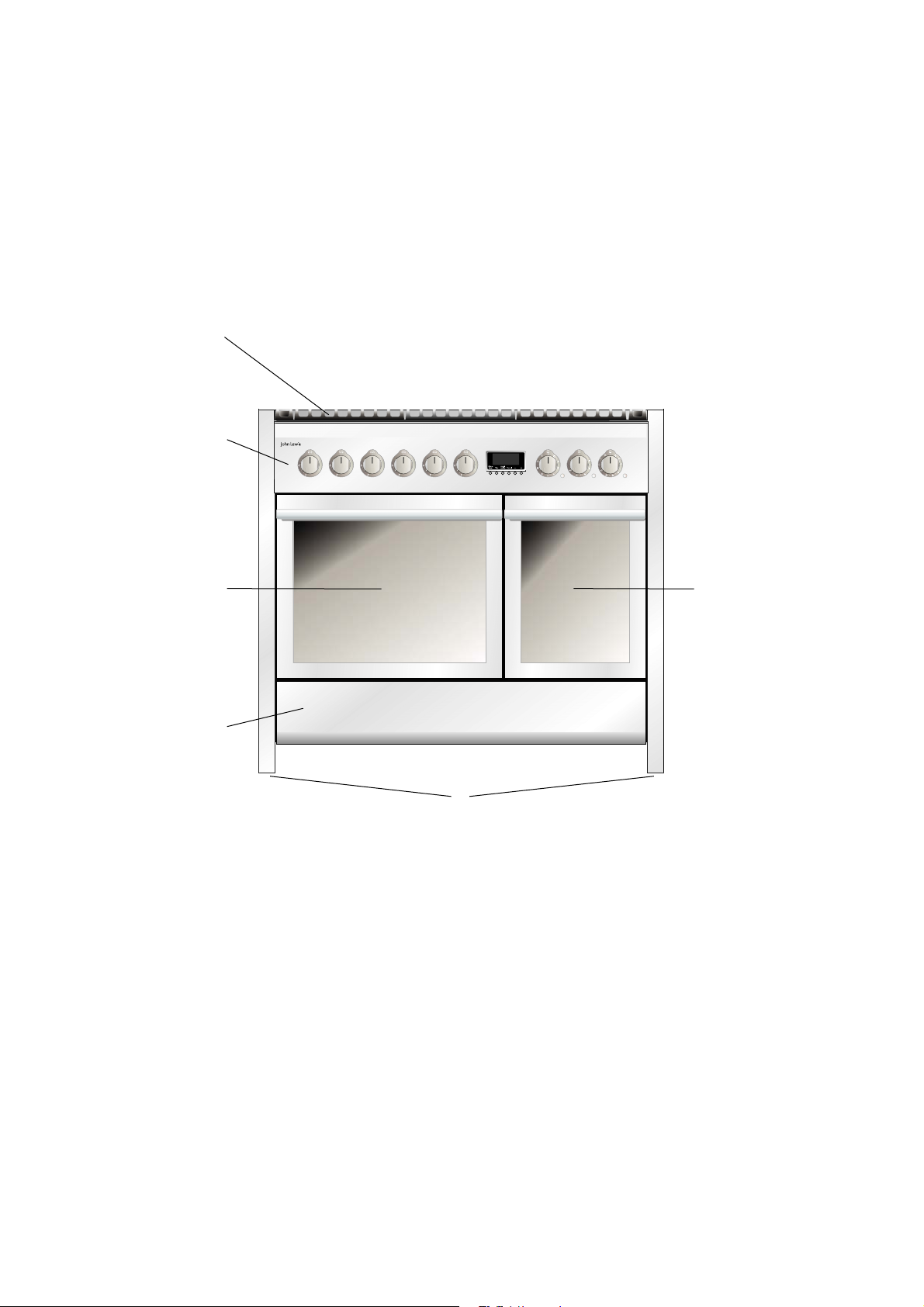
Description of the Appliance
1 Cooktop
2 Control Panel
3 Multifunction Main Oven
4 Conventional Second Oven
5 Storage Drawer
6 Adjustable Feet
6
Page 7
Installation
It is dangerous to alter the specifications or attempt to modify this product in any way.
Care must be taken to ensure that the appliance does not stand on the electrical supply cable (not
supplied).
Any electrical work required to install this appliance should be carried out by a qualified electrician or
competent person.
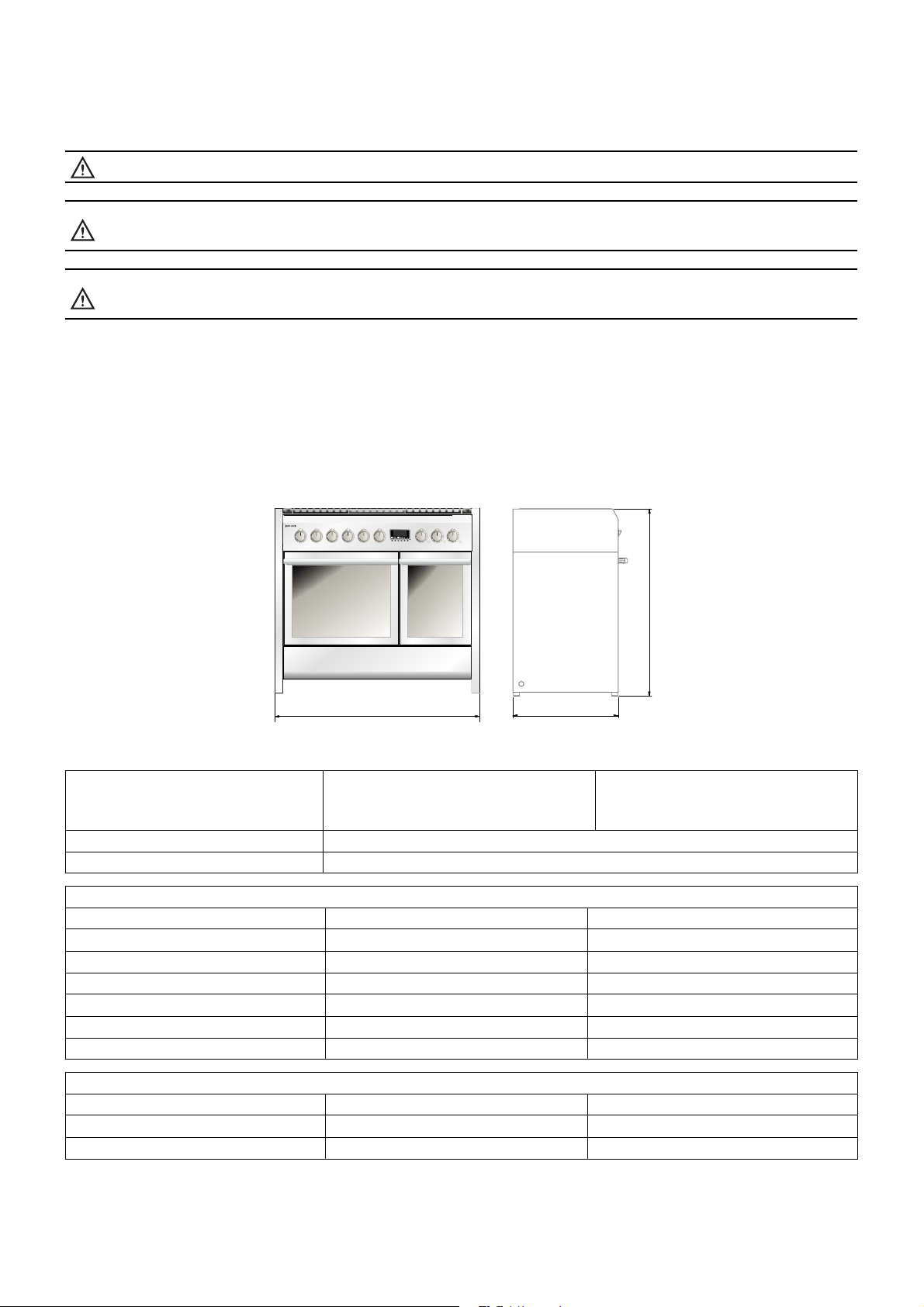
Technical Specifications
Width
Appliance dimensions
Connection voltage 230 V ~ 50Hz
Maximum connection load 3.9 kW
Position Type Power Watt Max/Min
Rear Left Semi-rapid 1750/440
Rear Centre Triple ring 3300/1500
Rear Right Rapid 3000/750
Front Left Triple ring 3300/1500
Front Centre Semi-rapid 1750/440
Front Right Simmer 1000/300
Depth
Height
Gas Hobs
998mm
599mm
900mm
Electric Ovens
Position Type Power
Left Multifunction 2.2 kW
Right Conventional 1.7 kW
7
Page 8
Electrical Connection
Any electrical work required to install this appliance should
be carried out by a qualified electrician or competent
person.
WARNING: THIS APPLIANCE MUST BE
EARTHED. Should the appliance power
supply cable need to be replaced, this must
be carried out by a Service Force agent (see
page 27). The manufacturer declines any
liability should this safety measure not be
observed.
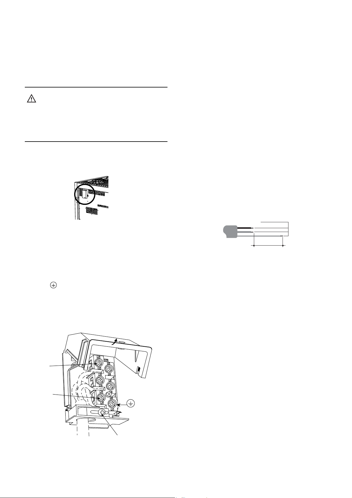
To replace the electric cable, it is necessary to access the
terminal board. It is located on the back of the appliance, at
the top left,
Proceed as follows:
Open the terminal board box;
•
• Unscrew the screw A that locks the cable;
Loosen the screw contacts and replace the cable with one
•
of the same length that corresponds to the specifications
in the table in section "Electric power cable section";
The "yellow-green" earth wire must be connected to the
•
terminal and must be approximately 20 mm longer
than the line cables;
• The neutral "blue" wire must be connected to the
terminal marked with the letter N;
• The line wire “brown” must be connected to the terminal
marked with the letter L.
(see diagram below).
Permanent connection
For permanent connection it is necessary to
install a double pole switch between the appliance and
the electricity supply (mains), with a minimum gap of 3mm
between the switch contacts and of a type suitable for the
required load in compliance with the current electrical
regulations.
The switch must not break the yellow and green earth
cable at any point.
Electric power cable section
According to the type of power supply, use a cable that
conforms to the following table.
Running at 230V1N~: use a tripolar cable type H05RR-F
2
(cable measuring 3 x 2.5 mm
91a
The end to be connected to the appliance must have the
earth wire (yellow-green) at least 20 mm longer.
).
PP
PP
.
0
#
8
Page 9
Gas Connection
The room containing the appliance should have an air
supply in accordance with B.S. 5440 part 2.
1. All rooms require an opening window or equivalent, and
some rooms will require a permanent vent as well.
2. For room volumes up to 5m³ an air vent of 100cm² is
required.
3. If the room has a door that opens directly to the outside,
and the room exceeds 10m³ no air vent is required.
4. For room volumes between 5m³ and 10m³ an air vent of
50cm² is required.
5. If there are other fuel burning appliances in the same
room B.S. 5440 part 2 should be consulted to determine
the air vent requirements.
6. The appliance must not be installed in a bed sitting room
of less than 20m or in a bathroom or shower room.
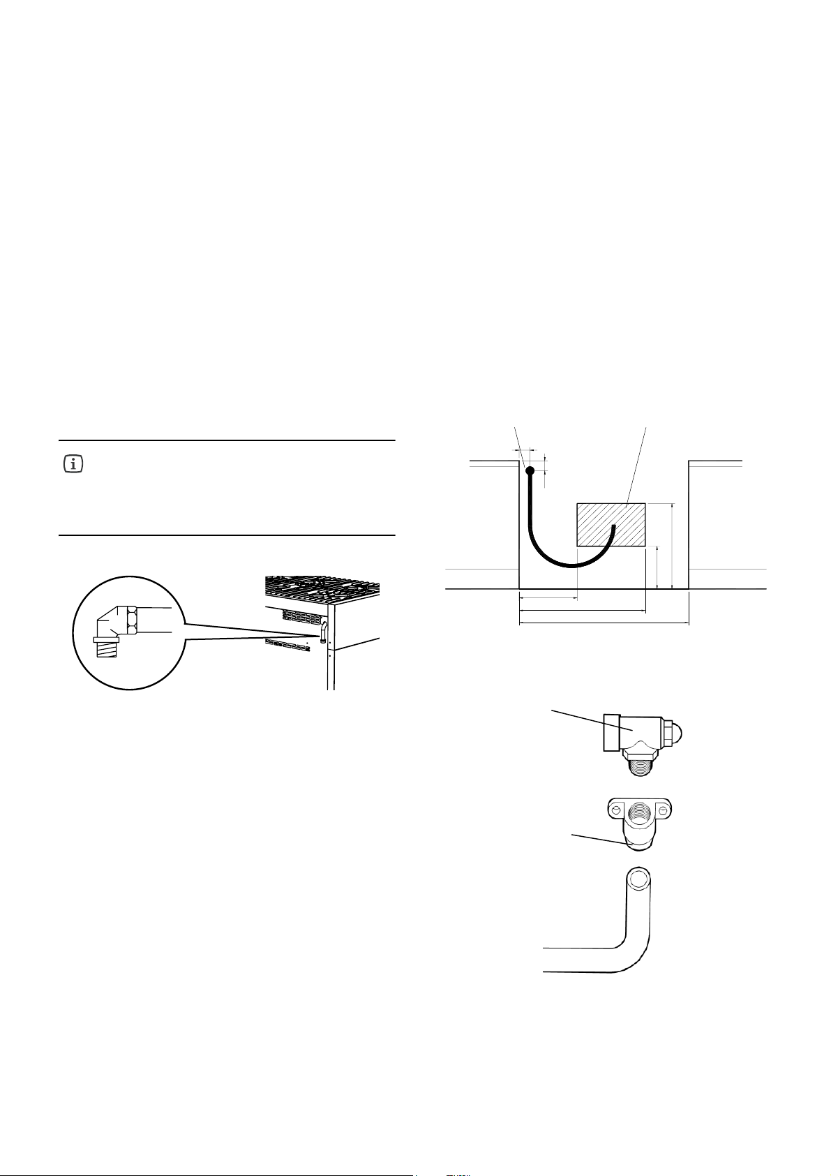
We recommend checking that the appliance
is properly set up for the type of gas
distributed. The threaded ½" gas connection
pipe is located at the rear on the right hand
side of the appliance.
The cooker is designed to match the depth of standard
600mm worktops. An adaptor back plate should, therefore,
be fitted within the shaded area shown to allow the cooker
to be pushed in fully and chased to the wall.
Connection to the cooker should be made with an
approved appliance flexible connection to BS 669. A length
of 0.9 to 1.25m is recommended. The length of hose
chosen should be such that when the cooker is in situ, the
hose does not touch the floor.
The temperature rise of areas at the rear of the cooker
that are likely to come in contact with the flexible hose do
not exceed 70°C.
*$6,1/(721
$33/,$1&(
/2&$7,21)25
%$<21(7&211(&725
%$<21(7&211(&725
(/%2:
%$<21(7
$'$3725
9
Page 10

Stability chain
The cooker is fitted with a stability device such as a
proprietary stability chain as shown and firmly secured to
the fabric of the building.
Whatever the position, remember to leave enough room
for the cooker to be pulled out for cleaning and service.
The wall behind the cooker between the hotplate and
450mm above, and across the width of the cooker, must be
an incombustible material such as ceramic wall tiles.
This appliance is designed not to project in front of
standard 600mm worktops (excluding handles). To achieve
the best fit the cooker must be pushed against the wall.
As this appliance is very heavy it should be
situated on a suitably hard surface as to
ensure servicing and installation is made
possible with minimal impact on the floor
surface.
MM-IN
MM-IN
MM-IN
MM-IN
MM-IN
10
Page 11

Conversion from Natural Gas to LPG
If the cooking appliance is set up for a different type of gas
than that available, its injectors must be replaced, the
minimum flow regulated. In order to replace the injectors
in the cooking hob, it is necessary to carry out the
following operations:
Fig. A
• remove the pan supports;
• remove the burners and burner caps (Fig. A);
• take out the injector (Fig. B) and replace it with one
suitable for the new type of gas (see "General injectors
table");
• replace the gas label (on the rear of the appliance) with
the new one provided with the injectors kit;
• refit all parts by following the disassembly instructions in
reverse order and taking care to position the burner cap
correctly on the burner.
Fig. B
Minimum flow of valved cooking
hob taps
Minimum flow of non-valved
cooking hob taps
• Switch on the burner and turn the control knob towards
the minimum flow position ;
• remove the knob;
• insert a small screwdriver into the rod of the tap and
adjust the internal screw Z until the correct low flame is
obtained;
• refit the knob.
=
Unscrew the adjustment screw Z to increase
the flow, or tighten it to reduce the flow. The
adjustment is correct when the low flame
measures approximately 3 or 4 mm. When
changing quickly from maximum to
minimum flow and vice versa make sure that
the flame does not go out.
• Switch on the burner and turn the control knob towards
the minimum flow position ;
• remove the knob;
• using a screwdriver, adjust the internal screw Z until the
correct low flame is obtained;
• refit the knob.
=
Connecting to LPG
Use a pressure regulator and connect to the cylinder in
compliance with the guidelines set out in standards
regulations in force.
L.P.G. cookers MUST NOT be installed
below ground level i.e. in a basement or
aboard any boat, yacht or other vessel.
General injectors table
TYPE OF GAS mBar INJECTOR NO. BURNERS
INJECTOR BY-PASS MAX. MIN.
115 44 GAP RAPID 3000 750 286 l/h
NATURAL 97 34 GAP SEMI-RAPID 1750 440 167 l/h
GAS 20 72 27 GAP SIMMER 1000 300 95 l/h
G20 (E) 128 60 GAP TRIPLE RING (A)* 3300 1500 314 l/h
128 60 GAP TRIPLE RING (D)* 3300 1500 314 l/h
LPG 85 44 GAP RAPID 3000 750 219 g/h
BUTANE 65 34 GAP SEMI-RAPID 1750 440 128 g/h
PROPANE 28-30/37 50 27 GAP SIMMER 1000 300 73 g/h
G30/G31 93 60 GAP TRIPLE RING (A)* 3300 1500 240 g/h
93 60 GAP TRIPLE RING (D)* 3300 1500 240 g/h
* Position A: front left, position D: centre rear (see also "Description of the cooktop").
POSITION TYPE
POWER Watts MAX.
CONSUMPTION
11
Page 12

Description of the cooktop
A Triple ring burner 3.30 kW
B Semi-rapid burner 1.75 kW
C Semi-rapid burner 1.75 kW
D Triple ring burner 3.30 kW
E Simmer burner 1.00 kW
F Rapid burner 3.00 kW
%
'
)
Assembly
Fitting the adjustable feet
Before assembling the cooker remove all the
parts that are not firmly attached to it, in
particular the pan supports and burners. To
lighten the weight of the cooker, the
accessories inside the ovens may also be
removed, preventing accidental damage
during the overturning process.
The cooker is delivered with the feet removed. Before
moving and connecting up the cooker, take the feet from
the packaging and screw them onto the cooker. This can be
done in one of two ways:
$
Should it be necessary to move the cooker,
screw the feet in completely and carry out
the final levelling adjustment only when the
gas and electrical connections have been
made.
&
(
Levelling the cooker to the floor
After having made the electrical and gas hook-ups, level the
cooker to the floor using the adjustable feet that were
previously screwed onto the bottom of the cooker.
A Lifting the cooker off the floor.
B Laying the cooker on its back.
$
The final adjustment of the feet to level the Cooker to the
floor will be done after the gas and electrical connections
have been made.
%
Should it be necessary to drag the cooker,
screw the feet in completely and carry out
the final regulation only when the other
operations are completed.
12
Page 13

The Control Panel
The front control panel
All the commands and controls for the using the hob and
ovens are on the front control panel.
Description of hob burner knob
The flame is lit by simultaneously pressing in and turning the
control knob anticlockwise to the low flame symbol .
To regulate the flow of the flame, turn the control knob
between the maximum and minimum settings. Turn
off the burner by returning the
control knob to position .
Layout of burners - Description of
symbols
REAR LEFT
Description of electric oven knobs
The main electric oven is controlled by two knobs: function
control knob and thermostat control knob. They
allow you to choose the most suitable cooking function for
different food types, by switching on the appropriate heating
elements and setting the required temperature
(from 50°C to Max).
Below the oven knobs there are two warning lights: the
red light signals the oven is working; the orange light
indicates that the required temperature has been reached.
The orange light switches on and off to indicate when
heating automatically kicks in to maintain the temperature
inside the oven at the level set on the thermostat knob.
The oven has an internal light. The light is always on
while the oven is working. It can be switched on when the
oven is off, for cleaning purposes, by turning the function
control knob to the symbol .
REAR RIGHT
REAR CENTRE
FRONT CENTRE
FRONT LEFT
FRONT RIGHT
Description of symbols on the
function control knob
OVEN LIGHT
CONVENTIONAL COOKING
TOP HEAT
BOTTOM HEAT
GRILL
FAN GRILLING
PIZZA SETTING
FAN COOKING
DEFROST
13
Page 14

Description of second electric
Description and use of the LED
oven
The second electric oven is equipped with Conventional
cooking and is controlled by a single control knob.
This allows the user to choose the most suitable
temperature for different recipes, by switching on the
heating elements appropriately and setting the required
temperature (60 to Max). Using the same control knob
it is also possible to set the functions described below.
Below the
which indicates when the oven has reached the
temperature. The orange light switches on and off to
indicate when the heating automatically kicks in to
maintain the temperature inside the second oven.
The second oven has an internal light. The light is always
on while the oven is working. It can be switched on when
the oven is off, for cleaning purposes, by turning the
function
control knob
second oven knob there is an orange light,
required
control knob to the symbol .
digital display
The LED digital display can electronically control the
operation of the oven. Setting the time enables the user
to set the oven to switch on and off at the required times.
TIMER BUTTON
COOKING TIME BUTTON
END OF COOKING BUTTON
Description of symbols on second
electric oven
OVEN LIGHT
q*=T
CONVENTIONAL COOKING
BOTTOM HEAT
TOP HEAT
GRILL
control knob
MANUAL OPERATION BUTTON
DECREASE VALUE BUTTON
INCREASE VALUE BUTTON
Setting the time
When using the oven for the first time, or after a power
cut, the display flashes regularly showing .
Press the Manual
Value button - or + within 5 seconds until the current
time appears in the display.
Before setting the End of Cooking timer, you
must select the required cooking function and
temperature.
button to stop the display flashing. Press the
14
Page 15

Semi-Automatic Cooking
This setting automatically switches off the oven when
required and should be used when the oven is already on.
Press the Time button and the display will show the
figures ; hold down and at the same time press
of the value buttons - or + to set the cooking duration.
Release the Time button to begin the countdown of the
selected cooking time. The display will show the
current time together with symbols AUTO and .
one
The oven switches off regardless of the cooking function
or temperature selected and the AUTO symbol flashes.
To stop the AUTO symbol flashing, press the Manual button.
Once the bell is switched off, the oven begins to operate again.
To switch the oven off, turn the function control knob and
thermostat control knob to “0”.
Timer
The LED digital display can also be used as a simple
timer.
Automatic Cooking
This setting switches the oven on and off automatically.
Press the Time button and the display will show the
figures ; hold down and at the same time press one
of the Value buttons - or + to set the cooking duration.
the End of cooking button. The display shows the
Press
sum of the current time plus the cooking duration. Hold
down and at the same time press the value buttons - or +
to set the time you would like the food to be ready for.
Release the
programmed count
together with symbols AUTO and .
End of cooking button to begin the
down. The display shows the current time
After you have set the Automatic timer,
press button Time to see the remaining
cooking time. Press button End of cooking
to see the end of cooking time.
End of cooking
At the end of the programmed cooking time, the oven
switches off automatically and an intermittent bell
rings. After switching off the bell, the display once again
shows the current time together with symbol , which
indicates the oven has returned to the manual setting.
Using the display as a simple timer does not
interrupt the operation of the oven at the end
of the set time.
Press
the Minute timer button and the display shows the
figures . Hold down Minute timer and at the same time
press the value buttons - or +. Release the button Minute
timer to begin the programmed countdown and the display
shows symbols and .
After programming the timer, the display once more shows
the current time. To display the time remaining
the Minute timer button.
You cannot set inconsistant values when using
the automatic timer. (For example, a cooking
time that would be longer than the required
end of cooking time).
again, press
Cancelling set data
Whilst the timer is set, hold down the button for the
function you wish to cancel and reduce the time to the
value using the Value buttons - or +. Cancelling
the selected timer function means the cooker reverts to
the manual setting.
Adjusting the volume of the bell
The volume of the bell can be varied (3 levels) by pressing,
whilst it is ringing, the Value button -
Switching off the bell
You can switch it the bell off manually by pressing the
Manual button or any of the timer buttons. The bell
automatically stops ringing after seven minutes.
After pressing the Manual button the oven
begins to operate once again: to switch it off,
turn the function control knob and the
thermostat control knob to “0”.
Changing set data
The times set for cooking and ending can be changed by
holding down the required function button and pressing the
Value buttons - or + until the display shows the new times.
15
Page 16

Using the Hob
Before use make sure the Burner caps and
Pan supports are correctly fitted.
During normal use the cooker will get hot.
Caution should therefore be used. Do not
allow children to approach or play with the
cooker; whenever the hob is in use and in the
necessary cooling down period, take care to
position the saucepans in a way that prevents
burns or overturning.
Switching on the burners
The hob burner control knobs have the following symbols:
tap closed
high flame
low flame
The low flame setting is found by turning the control knob
anti-clockwise all the way. All intermediate settings are
selected between the high and low flame. The control knob
cannot be set between high flame and tap closed.
Suggestions for using the hob
burners correctly
The diameter of the base of saucepan or frying pan should
fit the diameter of the burner used (see table below). The
burner flame must never be wider than the diameter of the
pan. Always use pans with a flat base. Where possible use pans
with a lid, as this reduces the level of gas required. Using only
the required amount of water for vegetables, potatoes, etc,
will reduce the cooking times.
«
Burner Pan Diameter (in cm)
Rapid from 24 to 26
Semi-rapid from 16 to 22
Simmer from 8 to 14
Triple ring from 16 to 35
One touch ignition and safety valve
The hob burners are equipped with a "one touch" ignition
system. To switch on one of the burners, press in the
appropriate control knob and turn it anti-clockwise to the
low setting . Hold in the control knob to activate the
"one touch" ignition. Continue holding the control knob
in for 10seconds, to allow the safety valve to open.
Should the burner switch off accidentally, the safety
(thermocouple) valve will close and stop the flow of gas,
even when the tap is open.
Manual ignition
To manually light one of the burners, press the appropriate
control knob in and turn it anti-clockwise to the low
setting and use a piezo gas lighter to ignite the gas.
Adjust the flame and release the knob.
Switching off the burners
At the end of the cooking, return the knob to position .
16
Page 17

Using the Ovens
General warnings
During normal use the cooker will get hot.
Caution should therefore be used. Avoid
leaving the oven door open during use and
immediately after cooking, the heating
elements will still be hot.
Do not allow children to approach or play
with the cooker.
Do not allow children to sit or climb on the
drop down doors.
Do not cook food on the base of the oven.
When using the oven for the first time, or
after a power cut, the display flashes regularly
indicating , to set the display, refer to the
section "Setting the Time" on page 14.
Do not attempt to disassemble the oven door
without consulting the relative instructions
carefully (refer to the section "Removing the
oven door") on page 25. The hinges on the
oven door may injure the hands.
Storage drawer
The Storage Drawer is situated beneath the ovens. Only
store metal trays or cooking accessories in this
compartment.
Do not store inflammable material such as
cloths, paper or similar; the heat from the
oven could create a fire risk.
Using the electric multifunction
main oven
The LED digital display, the left and
centre oven control knobs only apply to
the main multifunction oven, they do not
operate the Conventional second
oven.
Heating failure of the oven
If during normal use there is a failure in the heating of the
oven and the programmer display begins to flash and
returns to :
• Check to see if there has been an electrical power failure.
If the failure occurs again after the cooking program has
been restarted, this means that the safety device has been
tripped. The safety device will intervene in the event of a
thermostat fault and prevent the oven overheating. In such
cases we recommend that you do not use the oven again
and you contact the John Lewis extended warranty
administrators, see "Repairs - After Sales Service” on
page 27.
Switching on the ovens for the first
time
The first time the oven is used, the oven may smoke or
give off an acrid smell. This is caused by oily residues from
manufacturing and could transfer unpleasant odours or
flavours to the food. Before using the ovens for the first
time, heat the ovens to their maximum
temperatures for 30 to 40 minutes with the doors
closed and wait until the smoke or odours have
stopped.
17
Page 18

To prevent any steam in the oven from
scalding you as you open the oven door, turn
the function control switch to “0”, or function
; open the door in two stages
door partly open (approximately 5
5 seconds, then open the door completely.
Should you need to adjust the food, leave the
door open for as short a time as possible to
prevent the oven temperature from lowering
to such an extent as to jeopardise the
cooking. You may need to
cooking time.
. Hold the
cm) for 4 -
add a little extra
Conventional cooking
Turn the function control knob to position and the
thermostat control knob to the required temperature.
For heating only above or below the food, set the function
control knob to position (Top Heat) or (Bottom
Heat). For a more even heat throughout the oven cavity,
turn the function control knob to position .
Grilling
Turn the function control knob to position and the
thermostat control knob to the maximum temperature
setting (Max).
Defrosting
Turn the function control knob to position and leave the
thermostat
on bu
around the oven, encouraging the frozen food to defrost.
control knob in position . The fan is switched
t no heat is used. Room temperature air is circulated
Switching off the oven
The oven is switched off by turning the thermostat control
knob to position .
Using the second oven with
conventional cooking
The right hand oven control knob only applies
to the conventional second oven, it will not
operate the main multifunction oven.
After preheating and putting the food in the
oven an air flow between the upper side of
the door and the lower side of the hob may
be noticed. In case that does not happen,
switch off the appliance and contact the
Technical Service immediately.
Fan cooking
Turn the function control knob to position and the
thermostat control knob to the required temperature.
Cooking times and temperatures can be reduced.
Fan grilling
Turn the function control knob to position and the
thermostat
setting (Max).
control knob to the maximum temperature
The
second is equipped with:
• A heating element positioned on the base of the oven
(Bottom Heat);
• A heating element positioned on the ceiling of the oven
(Top Heat) + a grill element.
18
Page 19

Switching on the second oven for
the first time
The first time the oven is used, the oven may smoke or
give off an acrid smell. This is caused by oily residue from
manufacturing and may transfer unpleasant odours or
flavours to food. Before putting food in the oven,
heat the second oven to the maximum temperature
for 30-40 minutes with the door closed and wait
until the smoke or odour has stopped.
To start heating the
(from 60 to Max) or the required function by turning the
thermostat
control knob.
second oven, select the temperature
Cooking with the grill (second
oven)
Turn the thermostat control knob to position and let
the second oven preheat for approximately 5 minutes. For
correct operations, position the grill on the third shelf
support from the bottom. To vary the intensity of the heat
move the grill pan away from the grill by lowering the grill
pan to a different shelf position. This accomodates personal
taste and different cooking requirements. A cooling system
prevents the control knobs from getting too hot.
Switching off the second oven
The oven is switched off by returning the thermostat control
knob to “0”.
19
Page 20

Cooking suggestions
Suggestions for using the oven
correctly
The multifunction oven allows you to cook
different foods in the best way; using the fan,
conventional cooking or with the grill, for
example. The oven door should be closed
for all types of cooking.
Conventional cooking
When using this setting, the heat comes from the top and
the bottom elements. This allows you to cook on a single
middle level. If the dish requires extra base browning or
top browning, use the lower or upper shelf supports.
Conventional cooking is recommended for all foods that
require high cooking temperatures, or long brazing times.
This system is also recommended when cooking with
recipients made of terracotta, porcelain and similar
materials.
Fan cooking
With this type of cooking, the air inside the oven is heated
by the element around the fan situated behind the back
panel. The fan circulates hot air to maintain an even
temperature inside the oven. The benefits of cooking with
this function are:
As the fan oven quickly reaches temperature, it is not
usually necessary to preheat the oven, however for certain
foods e.g. bread, scones, soufles, etc. the best results are
achieved if you preheat the oven first.
Fan oven cooking generally requires lower temperatures
than Conventional cooking. Follow the recommended
chart on page 21.
The fan oven has uniform heating on all shelf positions.
This means that batches of the same foods can be cooked
in the oven at the same time.
There is no mixing of flavors between dishes so sweet and
savoury foods can be cooked at the same time.
Grilling
Pour 1 or 2 glasses of water into the drip
tray to avoid smoke forming due to drops of
juice or fat. While cooking with the grill, the
drip tray should always be positioned in
the 1st guide from the bottom.
Fan grilling
A combination of the grill and fan oven .
This type of cooking allows the heat to penetrate gradually
into the food, even though the surface is directly exposed
to the grill. Cooking is more gentle and can take a little
longer. Suitable for: thicker meat; poultry.
Cooking meat and fish
Meat to be cooked in the oven should weigh at least 1kg.
Tender meat that you want cooked rare (roast beef, fillet,
etc.), or which should be well cooked on the outside and
retain all the juices on the inside, should be cooked on high
temperatures for a short time (200-250°C). White meat,
poultry and fish should be cooked on lower temperatures
for a longer time (150-175°C).
The ingredients for any sauce should only be placed in the
baking tray, at the beginning, if the cooking time is short.
Oherwise, they should be added in, in the last half hour. Meat
can be placed in an ovenproof dish or directly onto the shelf,
below which a drip tray should be placed to collect the juice.
Press the meat with a spoon to check if it is done. If it is
firm, it is cooked.
At the end of the cooking, wait at least 15 minutes before
carving the meat, so as not to lose the juices. Before serving,
plates can be warmed in the oven at minimum temperature.
Baking
Beaten mixtures should stick to the spoon because excess
liquid will prolong the cooking time. Sweets require
moderate temperatures (generally between 150-200°C)
and you should preheat the oven (about 10 minutes).
The oven door must not be opened until at least ¾ of the
way through the cooking time.
With this type of cooking the heat comes from the top grill
element. Preheat the grill for a few minutes before cooking
and sealing meats. Lightly brush meat and fish with a
little oil and place on the grid in the grill. Adjust the heat
during grilling by moving closer to or further away from the
grill element. This avoids burning the surface and cooking too
little inside. The food should be turned over during cooking
as required. Suitable for: fairly thin meat
20
Page 21

Recommended cooking tables
Cooking times vary according to the texture, consistancy and volume of the food. We recommend monitoring your first
attempts and checking the results, as similar results are obtained by cooking the same dishes in the same conditions. The
following three tables (I, II and III) provide guidelines.
Table of fan and conventional cooking times (I)
TYPE OF COOKING QUANTITY
BAKING
WITH BEATEN MIXTURE, IN A TIN
WITH BEATEN MIXTURE, ON THE DRIPPING PAN
SHORT PASTRY, PIE BASE
SHORT PASTRY WITH MOIST FILLING
SHORT PASTRY WITH DRY FILLING
MIXTURE WITH NATURAL LEAVENING
SMALL CAKES
MEAT
VEAL
BEEF
ENGLISH STYLE ROAST BEEF
PORK
CHICKEN
STEWS
BEEF STEW
VEAL STEW
FISH
FILLET, STEAK, COD, HAKE, SOLE
MACKEREL, TURBOT, SALMON
OYSTERS
KG.
1
1
0.5
1.5
1
1
0.5
1
1
1
1
1-1.5
1
1
1
1
1
POSITION OF SHELF FROM
CONVECTION TRADITIONAL CONVECTION TRADITIONAL
1-3
1-3
1-3
1-3
1-3
1-3
1-3
2
2
2
2
2
1
1
1-3
1-3
1-3
BOTTOM
2
2
3
2
2
1
3
2
2
2
2
2
2
2
2
2
2
TEMPERATURE
°C
175
175
175
175
175
175
160
180
180
220
180
200
175
175
180
180
180
200
200
200
200
200
200
175
200
200
220
200
200
200
200
180
180
180
TIME IN
MINUTES
60
50
30
70
45
50
30
60
70
50
70
70
120
110
30
45
20
BAKES AND PASTRIES
BAKE
PASTA
VEGETABLE
SWEET AND SAVOURY SOUFFLÉS
PIZZA
• The times refer to cooking on one shelf only; for more than one shelf increase the time by 5-10'.
• The cooking times do not include preheating which takes approximately 1
• When cooking on more than one shelf, the guide
• For beef, veal, pork and turkey roasts, either with bone or rolled, increase the time by 20'.
BAKE
lines given for the shelf position are the best positions.
0.75
0.5
2
2
1-3
1-3
1-3
1-3
0'.
21
2
2
2
2
185
185
180
200
200
200
200
220
60
50
50
30
Page 22

Table of cooking times with grill and fan grilling (II)
TRADITIONAL GRILLING
TYPE OF COOKING QUANTITY
CHICKEN
TOASTED SANDWICHES
SAUSAGES
PORK CHOPS
FISH
GRILLING WITH THE FAN GRILL
TYPE OF COOKING QUANTITY
ROAST PORK
ROAST BEEF
CHICKEN
• The dripping pan for collecting cooking juices should always be positioned in the 1
KG.
1-1.5
0.5
0.5
0.5
0.5
KG.
1.5
1.5
1.2
Table of defrosting times (III)
DEFROSTING
POSITION OF SHELF
FROM BOTTOM
3
4
4
4
4
POSITION OF SHELF
FROM BOTTOM
2
3
2
st
guide from the bottom.
TEMPERATURE
°C
MAX
MAX
MAX
MAX
MAX
TEMPERATURE
°C
170
220
190
TIME IN
MINUTES
30 PER SIDE
5 PER SIDE
10 PER SIDE
8 PER SIDE
8 PER SIDE
TIME IN
MINUTES
180
60
90
TYPE OF COOKING QUANTITY
READY-TO-EAT DISHES
MEAT
MEAT
MEAT
• Defrosting at room temperature has the advantage of not modifying the flavour and appearance of food.
KG.
1
0.5
0.75
1
POSITION OF SHELF
FROM BOTTOM
2
2
2
2
TIME IN
MINUTES
45
50
70
110
22
Page 23

Maintenance and Cleaning
Before cleaning or carrying out maintenance,
switch off the power supply to the cooker and
close the gas taps.
Do not clean the surfaces of the cooker when
they are still hot.
Do not use pressure or steam spray guns to
clean the cooker.
Cleaning stainless steel
To clean and preserve stainless steel surfaces and remove
the toughest stains, always use
products should not contain chlorine- based
abrasives or acid substances, alternatively use a
little warm vinegar.
Pour the product onto a damp cloth and wipe the steel
surface. Rinse carefully and dry with a soft cloth.
Do not under any circumstances use metallic
sponges or sharp scrapers that may damage the
surfaces. Only use non-scratch, non-abrasive sponges and,
if necessary, wooden or plastic utensils.
a specific products; these
Cleaning enamelled surfaces
Clean with a non-abrasive sponge dampened
with soap and water. Grease stains can easily be
with hot water or a product specifically made for cleaning
enamel. Rinse carefully and dry with a soft cloth.
Do not use products containing abrasives, scouring
pads, steel wool or acid, which may spoil the
surfaces. Do not leave acid or alkaline substances on the
enamel (lemon juice, vinegar, salt etc.).
removed
Cleaning the pan supports and
burners
To clean the pan supports and hob burners, remove them
from the
above) and soak them in warm soapy water with a mild,
non-abrasive detergent for about ten minutes. Rinse
and dry thoroughly.
Always check that the burner opening and jets are
free of any soiling or impediments.
Be sure to refit the burners correctly, checking the flame is
uniform.
We recommend carrying out this operation at least once a
week and each time as necessary.
ir housing by lifting them upwards (see diagram
Cleaning the igniter plugs and
thermocouples
Cleaning the control knobs and
control panel
Clean the control knobs and panel with a damp cloth.
In order for the igniter plugs and thermocouples to operate
correctly, they must be kept clean at all times. Check them
frequently and, if necessary, clean them with a
Any dry residue should be removed with a toothpick or
needle, taking care not to damage the insulating
ceramic part.
23
damp cloth.
Page 24

Cleaning the oven
In order to maintain the ovens efficiency and for hygienic
reasons, it should be cleaned regularly, each time it is used
if possible, after leaving it to cool: in this way it is
possible to remove any residue more easily preventing it
from burning the next time the oven is used.
Clean the stainless steel and enamelled parts as described
in the corresponding sections "Cleaning stainless steel" and
"Cleaning enamelled surfaces".
Take out all the removable parts and wash them separately.
Rinse and dry thoroughly with a clean cloth.
Cleaning the Catalytic oven liners
Never use detergent products to clean this type of
oven.
The walls of the oven can be cleaned using white vinegar
and wiped with a cloth. Afterwards, heat the
oven cavity (for at least one hour) to 150°C
to clean the liners. When the oven has cooled, wipe it
again with a damp cloth.
Cleaning the door
We recommend you always keep the oven doors clean.
Use kitchen roll or on tougher stains use a damp cloth and
household detergent to clean the doors.
Spray products for cleaning the oven must
not be used to clean the fan and the
thermostat sensor inside the oven.
Replacing the light bulb
Before carrying out maintenance, switch off
the power supply to the cooker.
Proceed as follows:
• Open the oven door.
• Unscrew the glass safety cap anti
bulb and replace it with another one suitable for high
temperatures (300°C) with the following
specifications:
Voltage: 230V/50Hz
Power: 15 Watts
Attachment: E14
• Refit the glass cap and switch on the power.
check that the oven light is working by turning the
function control knob to the light setting .
-clockwise; unscrew the
You can
24
Page 25

Special Maintenance
Occasionally, it is necessary to maintain or replace some
parts that are subject to wear and tear. Specific instructions
are given below for each type of maintenance.
Before carrying out maintenance, switch off
the power supply to the cooker and close the
gas taps.
Removing the oven door
The oven door can be removed completely to make
cleaning the oven easier. Though this is possible, the
door is heavy, therefore this job should only be carried out
by someone with the strength to lift and carry the door. It
also requires a little expertise to refit it. If you are not
you will be able to do this, we recommend that you clean
the oven doors without removing them. In certain
circumstances, you contact the nearest authorized service
centre (see "Repairs - After Sales Service" on page 27).
To remove the door, proceed as follows:
• Open the oven door fully and release the safety catches
on the hinges (one for each hinge) by lifting them (A)
(see diagram below) back towards the oven door.
• Partially close the door until there is no more load
tension on the springs (the door will form an angle of
about 30°).
• Using both hands, grip the oven door on each side
and close the door whilst simultaneously lifting it
upwards.
• Pull the lower part of the door towards you to release
the hinges (B, see diagram below) from their seats.
If you need to clean between the panes of glass, turn the
door upside down (see diagram below), slide a soft bottle
brush into the space between the glass panes and brush
gently.
$
$
To refit the oven door, carry out the above
instructions the reverse. When the hinges
(B) are back in their seats, lower the oven
door fully down and lower the safety catches
on each hinge securely back in place (A)
$
%
%
$
Removing the shelf supports
The shelf supports can easily be removed for cleaning
and to help clean the oven walls. The shelf supports are
hooked to the oven walls in the three points indicated by
the arrows in the figure (detail 1).
• Press the top of the shelf support downwards as shown in
(picture 2) to release the shelf support from the upper pin.
• Lift the shelf support upwards and remove.
To refit the
reverse order. Set the lower part of the shelf support in the
respective pins and press the upper part towards the oven
wall until it hooks into the pin.
shelf support, carry out the instructions in the
Removal and cleaning the oven fan
The fan in main oven may occasionally need cleaning.
To remove the cover panel and fan proceed as follows
(see diagram below):
Make sure the power supply to the appliance
is switched off.
• Remove
and grill pan).
• Loosen and remove the four screws
cover panel.
• Remove the
• Use a coin to loosen the fixing nut
threading is in
• Remove fan
household detergent. Never use abrasive or
corrosive detergents, powdered products, or
metal scrubbers. Rinse the fan and dry thoroughly.
all the oven accessories (shelf supports, shelves
(A) from the fan
fan cover panel (B)
(C) of the fan (this
reverse, to loosen turn clockwise).
(D) and wash it using warm water and
$
%
&
$
'
CAUTION: After refitting the door, always
be sure to refit the hinge safety catches.
Refit the fan and
instructions.
25
cover panel by reversing the removal
Page 26

Something Not Working
If the appliance is not working correctly, please carry out
the following checks before contacting your local Service
Force agent.
Symptom Solution
The ignition does not work: • The plug is not properly inserted in the power socket.
• There is no current at the socket.
The burner does not ignite: • The gas is turned off.
• There is no ignition spark.
The flame has no uniform distribution: • The burner plate is improperly assembled.
• The burner is dirty.
IMPORTANT : If you call out an engineer to a
fault listed below, or to repair a fault caused
by incorrect use or installation, a charge will
be made even if the appliance is under
guarantee.
The inner lamp is not working: • The plug is not properly inserted in the power socket.
• There is no current at the socket.
• The lamp is defective.
The oven is not warming up: • The plug is not properly inserted in the power socket.
• There is no current at the socket.
The display light is blinking: • There has been a current interruption, the display needs to be
programmed again (see page 14).
26
Page 27

Repairs - After Sales Service
If your appliance is not working correctly; consult the fault
finding guides within this instruction book (Something not
working). If a fault occurs which you can not resolve
through following the advice and information contained
within this instruction manual, the next step is to contact
our extended warranty administrators on
0870 010 7887
They will give you details for your local Service Force
Centre.
Before calling out an engineer, please ensure you have read
the details under the heading "Something Not Working".
When you contact your local Service Force Centre you will
need to give the following details:
Spare parts
Always insist on genuine spare parts.
An authorised service engineer should service this product,
and only genuine spare parts should be used. Under no
circumstances should you attempt to repair the machine
your-self. Repairs carried out by inexperienced persons
may cause injury or serious malfunctioning. Contact your
local Service Force Centre. An authorised service engineer
always insist on genuine spare parts.
1. Your name, address and post code.
2. Your telephone number.
3. Clear and concise details of fault.
4. The purchase date and found on your receipt.
5. The model and serial number of the appliance.
So that you always have these numbers at hand, we
recommend you to make a note of them here:
Mod. : ………………………………………………………
PNC : ……...……………………………………….………
S.N. : ……..………………………………………..…..……
Your cooker is covered by a 3 year parts and
labour guarantee (see separate details given
at point of sale). Please retain your purchase
receipt safely for the service engineer to
verify the purchase details.
27
Page 28

John Lewis Partnership
171 Victoria Street
London SW1E 5NN
www.johnlewis.com
822 930 410 -A-01 11/06 ZS3625
 Loading...