

Page 1
HAD0901001C2
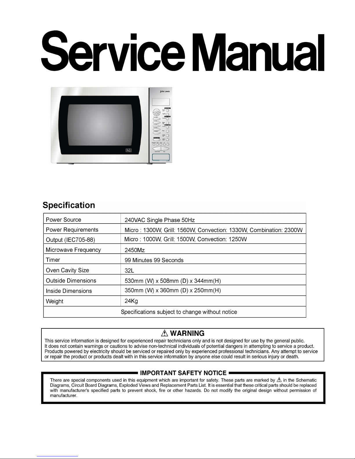
Microwave Oven
NN-CT878SBJQ
JLFSMWC003
32L OEM
United Kingdom
Page 2

NN-CT878SBJQ JLFSMWC003 32L OEM
2
1 Contents
1 Contents . . . . . . . . . . . . . . . . . . . . . . . . . . . . . . . . . . . . . . . . . . . . . . . . . . . . . . . . . . 2
2 Inverter Warnings . . . . . . . . . . . . . . . . . . . . . . . . . . . . . . . . . . . . . . . . . . . . . . . . . . 3
3 Feature Chart . . . . . . . . . . . . . . . . . . . . . . . . . . . . . . . . . . . . . . . . . . . . . . . . . . . . . . .3
4 Control Panel . . . . . . . . . . . . . . . . . . . . . . . . . . . . . . . . . . . . . . . . . . . . . . . . . . . . . . .4
5 Operation And Digital Programmer Circuit Test Procedure . . . . . . . . . . . . . . . . . . . 5
6 Schematic Diagram . . . . . . . . . . . . . . . . . . . . . . . . . . . . . . . . . . . . . . . . . . . . . . . . . 8
7 Wiring Diagram . . . . . . . . . . . . . . . . . . . . . . . . . . . . . . . . . . . . . . . . . . . . . . . . . . . . 9
8 Description of the Operation Sequence . . . . . . . . . . . . . . . . . . . . . . . . . . . . . . . . . . 10
9 Cautions to be Observed when Troubleshooting . . . . . . . . . . . . . . . . . . . . . . . . . . . 17
10 Part Replacement Procedure . . . . . . . . . . . . . . . . . . . . . . . . . . . . . . . . . . . . . . . . . . 20
11 Component Test Procedure . . . . . . . . . . . . . . . . . . . . . . . . . . . . . . . . . . . . . . . . . . . 29
12 Measurements and Adjustments . . . . . . . . . . . . . . . . . . . . . . . . . . . . . . . . . . . . . . . 31
13 Troubleshooting Guide . . . . . . . . . . . . . . . . . . . . . . . . . . . . . . . . . . . . . . . . . . . . . . . 32
14 Digital Programmer Troubleshooting Guide . . . . . . . . . . . . . . . . . . . . . . . . . . . . . . 35
15 Description of Operating instruction . . . . . . . . . . . . . . . . . . . . . . . . . . . . . . . . . . . .37
16 Exploded View . . . . . . . . . . . . . . . . . . . . . . . . . . . . . . . . . . . . . . . . . . . . . . . . . . . . . 38
17 Parts List . . . . . . . . . . . . . . . . . . . . . . . . . . . . . . . . . . . . . . . . . . . . . . . . . . . . . . . . . 39
18 Door Assy . . . . . . . . . . . . . . . . . . . . . . . . . . . . . . . . . . . . . . . . . . . . . . . . . . . . . . . . . 41
19 Escutcheon Base. . . . . . . . . . . . . . . . . . . . . . . . . . . . . . . . . . . . . . . . . . . . . . . . . . . . 42
20 Packing and Accessories . . . . . . . . . . . . . . . . . . . . . . . . . . . . . . . . . . . . . . . . . . . . . 43
21 Digital Programmer Circuit. . . . . . . . . . . . . . . . . . . . . . . . . . . . . . . . . . . . . . . . . . . . 44
22 Key Board Matrix . . . . . . . . . . . . . . . . . . . . . . . . . . . . . . . . . . . . . . . . . . . . . . . . . . . 46
© Panasonic Home Appliance Division. 2008
Unauthorized copying and distribution is a
violation of law.
Page 3
NN-CT878SBJQ JLFSMWC003 32L OEM
3
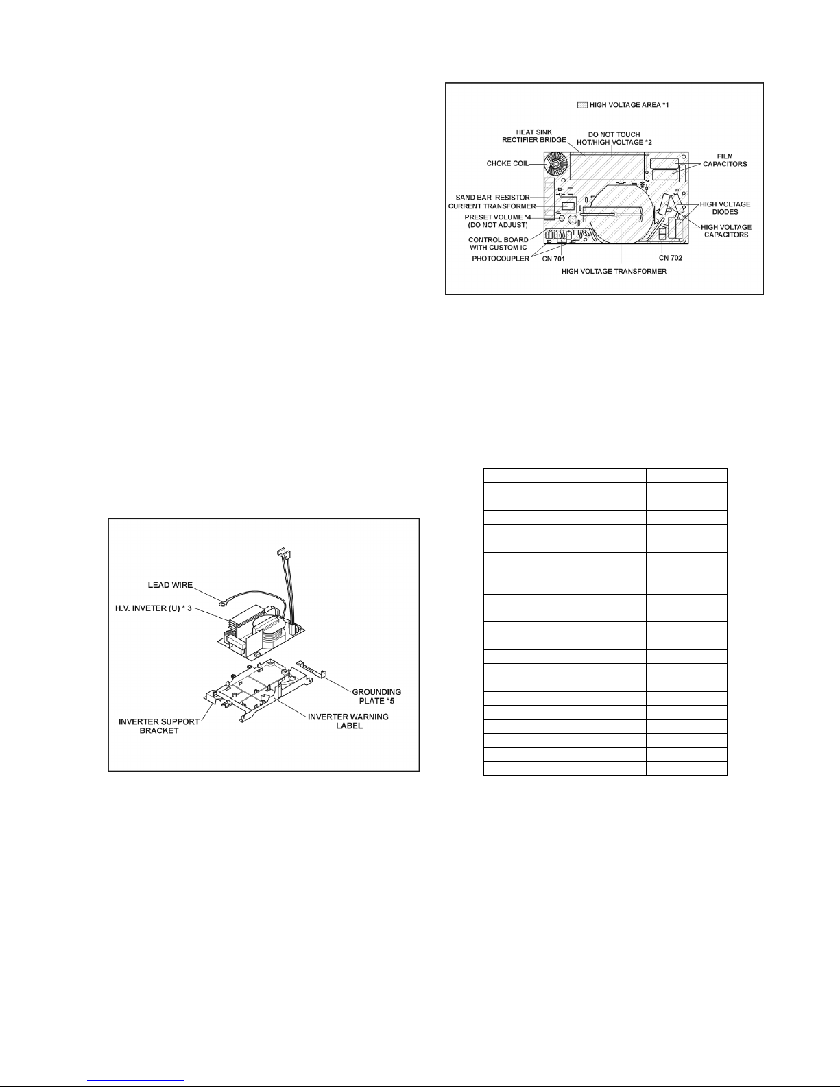
2 Inverter Warning
The inverter board looks like a regular PCB, however, this PCB
drives the magnetron tube using very high voltages and current.
It has
1. Very high voltage and high current
2. An Aluminium heat sink that becomes very hot
3. The capacitors on the inverter circuit will contain a high
voltage charge even when the oven is not operating.
Do not
1. Do not touch the circuitry as it contains very high voltages. When replacing the board please take extreme
care to avoid possible electric shock. High voltages may
remain in the circuit.
2. Do not touch the aluminium heat sink as it will become
very hot. It also contains high voltages.
3. Do not attempt to repair the inverter PCB as this can be
very dangerous. Replace the high voltage inverter circuit
as a complete unit. Return the old unit fully repacked
in the original shipping box and completed paper
work.
4. Do not adjust or tamper with the preset volume on the
inverter board. It is very dangerous to adjust this preset
without proper test equipment.
5. Do not test the oven while the inverter grounding strip or
screws are loose. It is very dangerous to operate the
inverter circuit board without a proper ground connection.
Inverter Grounding
Figure 1
Inverter PCB layout
Figure 2
3 Feature Chart
Function NN-A883
Microwave 6
Grill 3
Convection 17
Combination YES
Sensor reheat 2
Sensor cook 2
Sensor combination 4
Sensor crisp Weight defrost 3
Weight combination 8
Weight reheat Weight cook Memory cook Weight crisp Stage cooking 3
Delay/Stand YES
More/Less YES
Kg-> lb/oz YES
Clock 12H
Word prompt English
Step by Step LED
Page 4
NN-CT878SBJQ JLFSMWC003 32L OEM
4
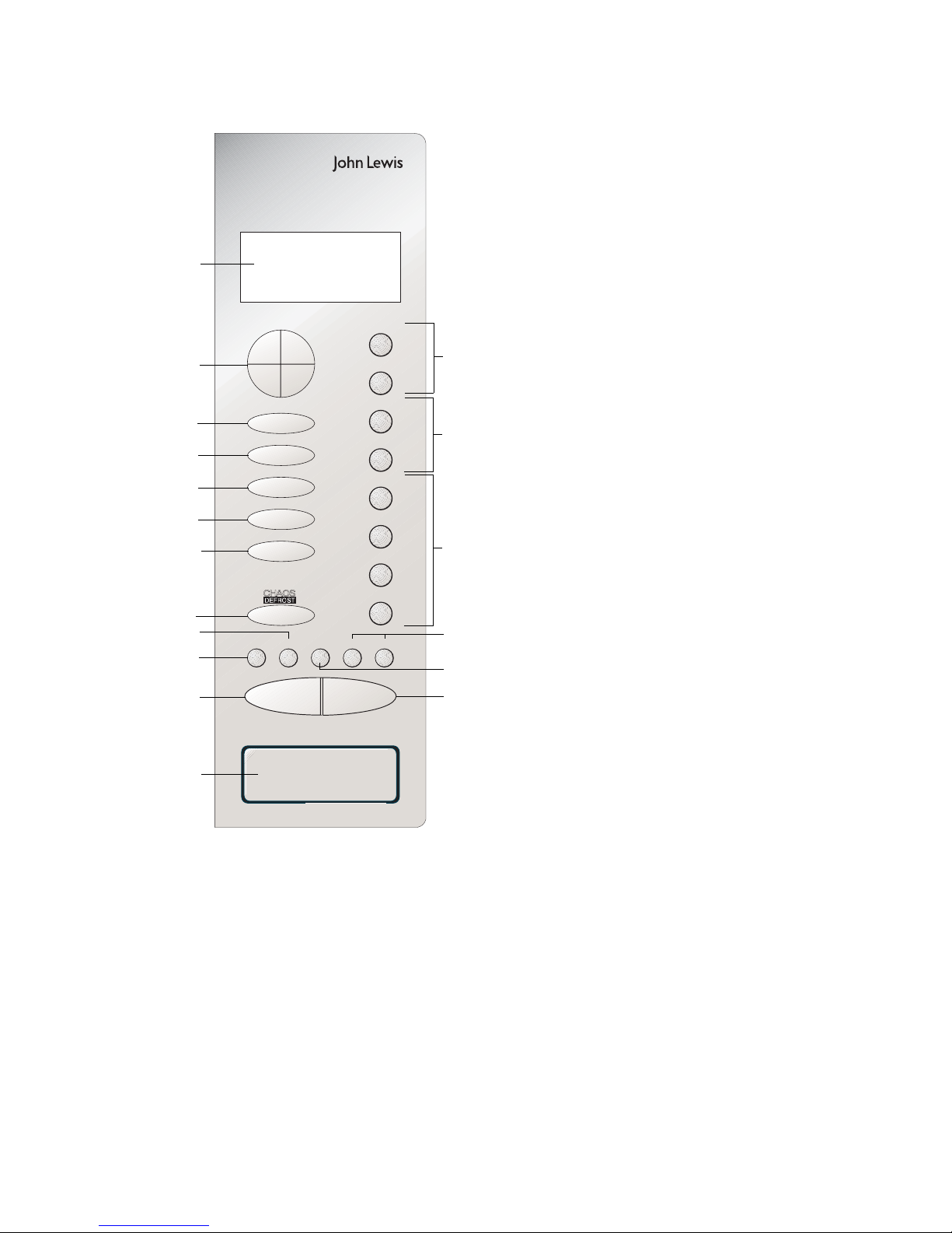
4 Control Panel
Potatoes
Micro Power
Grill 1-2-3
Convection
Turbo-Bake
Combination
CHAOS
g/
lb
oz
Delay/
Stand Clock more less
Stop/Cancel
Start
Reheat
Meal
Pastry/
Cake
Crispy
Top
Meat
Chicken
Roast Veg
Veg/Fish
JLFSMWC003
AUTO SENSOR
SENSOR COMBI
AUTO WEIGHT
10
min
1
min10sec
1
h
(1) Display Window
(2) Time Pads
(3) Auto Sensor Microwave
Programs
(4a) Auto Sensor Combination
Programs
(4b) Auto Weight Combination
Programs
(5) Auto Weight Defrost Programs
(6) Microwave Power Pad
(7) Grill Pad
(8) Convection Pad
(9) TURBO-BAKE Pad
(10) Combination Pad
(11) Delay/Stand Pad:
This can be used to delay a
cooking program for up to 9 hrs
99 mins., or used to time or for
standing (non-cooking) time.
(12) Clock Pad:
Refer to page 15 for setting the
clock.
(13) lb/oz Conversion Pad
(14) More/Less Pads
(15) Stop/Cancel Pad:
Before Cooking:
one press clears your instructions.
During Cooking:
one press temporarily stops the
cooking program. Another press
cancels all your instructions and
the time of day will appear in the
display.
(16) Start Pad:
Press to start operating the oven.
If during cooking the door is
opened or Stop/Cancel Pad is
pressed once, Start Pad has to
be pressed again to continue
cooking.
(17) Door Release Pad
(1)
(2)
(15)
(12)
(13)
(14)
(16)
(6)
(7)
(8)
(9)
(10)
(5)
(11)
(3)
(4a)
* The design of your control panel may
vary from the panel displayed (depending
on colour and shape of pads or buttons),
but the words relating to the pads will be
the same, and function in the same way.
(4b)
(17)
Page 5
NN-CT878SBJQ JLFSMWC003 32L OEM
5
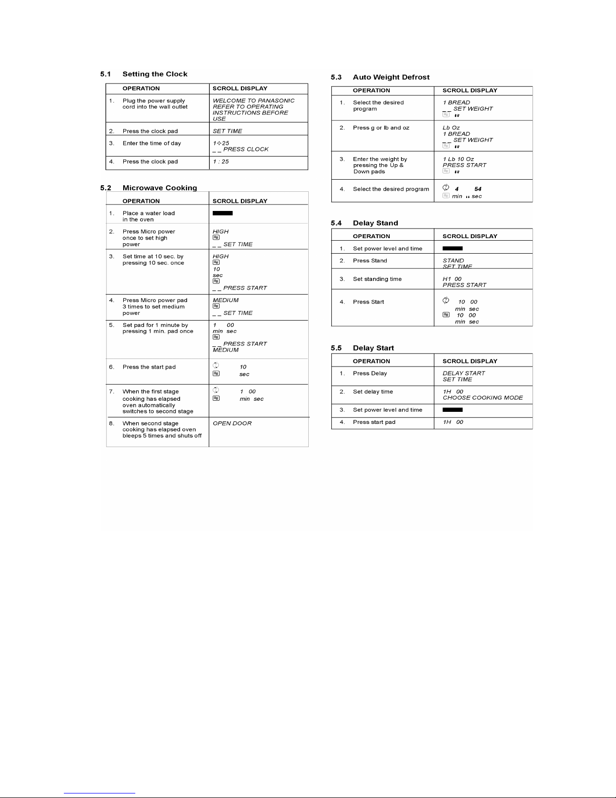
5 Operation And Digital Programmer Circuit Test Procedure
Page 6
NN-CT878SBJQ JLFSMWC003 32L OEM
6
Page 7
NN-CT878SBJQ JLFSMWC003 32L OEM
7
Page 8
NN-CT878SBJQ JLFSMWC003 32L OEM
8
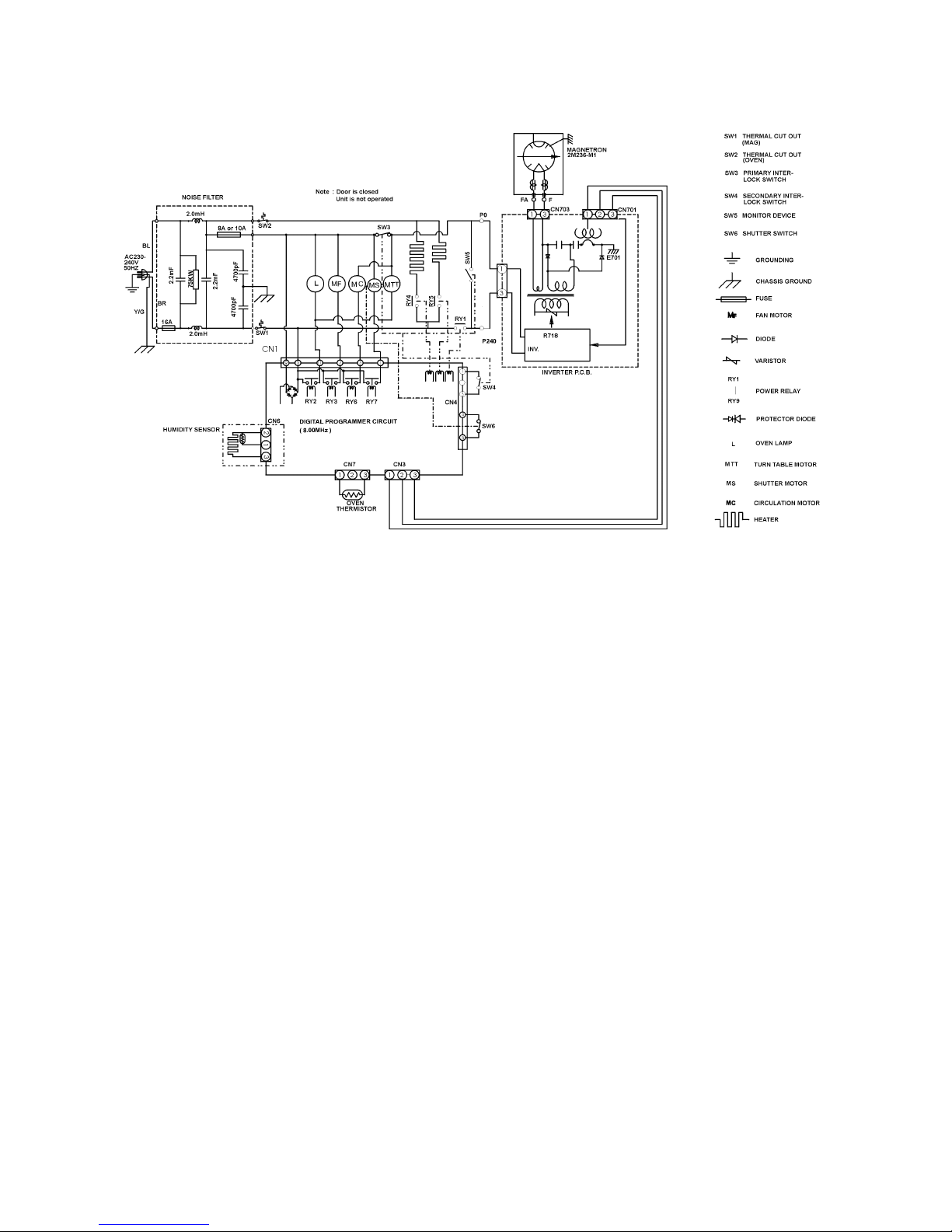
6 Schematic Diagram
Page 9
NN-CT878SBJQ JLFSMWC003 32L OEM
9
7 Wiring Diagram
Page 10

NN-CT878SBJQ JLFSMWC003 32L OEM
10
8 Description of Operating instruction
8.1. Variable power cooking control
The HIGH VOLTAGE INVERTER POWER SUPPLY controls
the output power by a signal from the digital Programmer circuit
DPC. The power relay (RY1) turns on to supply power to the
inverter circuit. The level of output power is controlled by the
drive signal level from the inverter circuit.
NOTE1: The ON/OFF time ratio does not correspond with
the percentage of microwave power since approximately 2
seconds are required for heating the magnetron filament.
NOTE: 2 If microwave cooking is over 8 minutes on HIGH
power, the fan motor rotates for 1 minute after cooking to
cool the oven and electrical components.
Duty cycles for microwave cooking
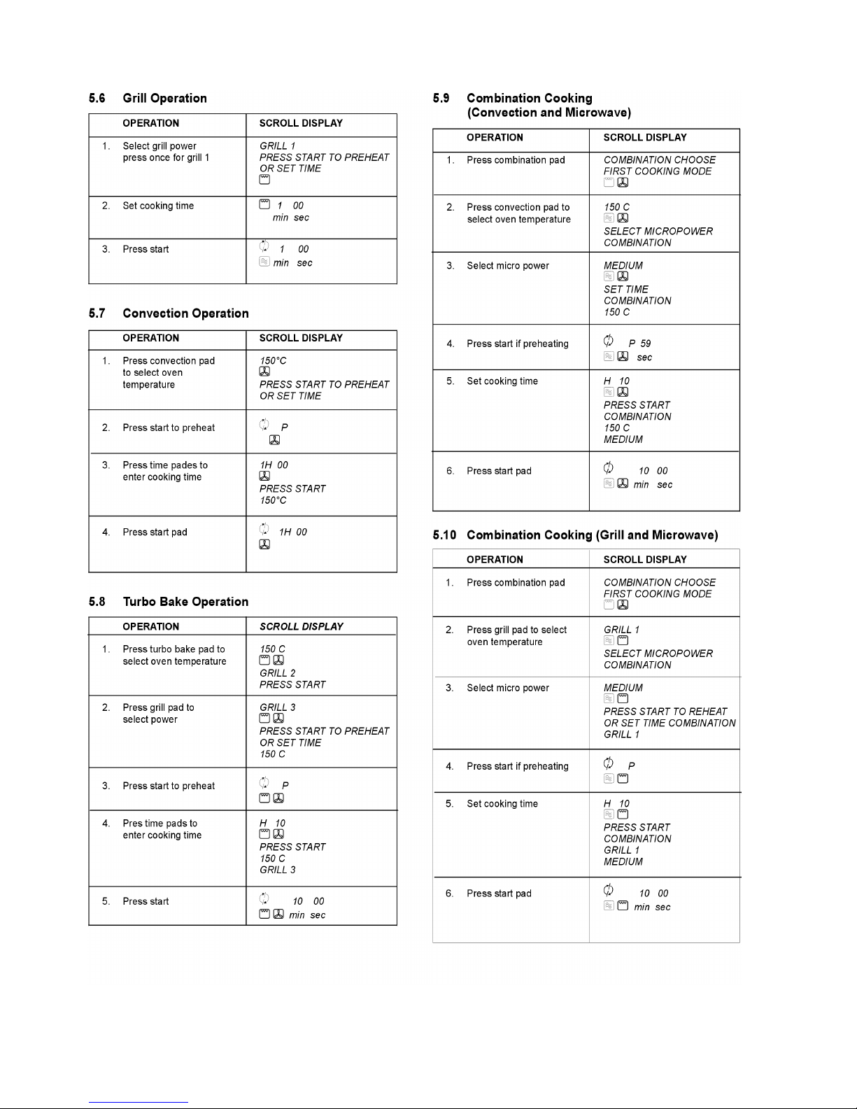
8.2. Grill Cooking
The digital programmer circuit controls the grill power by operating the power relay RY4 in the sequence shown in the table
below
Duty cycles for Grill Cooking
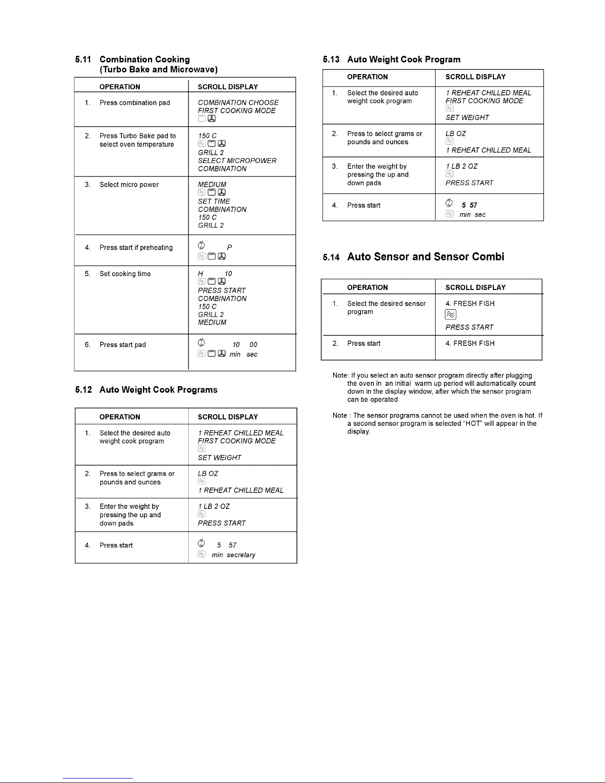
8.3. Auto weight defrost, Auto
weight Cook
When an auto control feature is selected and the start pad
pressed:
1. The digital programmer circuit determines the power level
and the cooking time and indicates the operating state in
the display. The table shows the corresponding cooking
times for each category and its respective weight.
2. When the cooking time in the display window has
elapsed, the oven turns off automatically via the control
signal from the digital programmer circuit.
Note: After auto cooking if the oven temperature is
over the predetermined temperature the fan motor
rotates to cool the oven and its components.
Defrost Menu’s
Weight Menu’s
Output Duty ON/OFF
ON time OFF time
High 1000W 22” 0”
Defrost 440W 16” 6”
Medium 600W 22” 0”
Low 440W 22” 0”
Simmer 440W 15” 7”
Warm 440W 8” 14”
Duty ON/OFF
ON Time OFF Time
Grill 1 66” 0”
Grill 2 54” 12”
Grill 3 42” 24”
Category 1st Touch Weight Cooking Time
Turbo Defrost 500g 8m 20s
Category 1st Touch Weight Cooking Time
1. Whole Chicken 1000g 18m 20s
2. Chicken Pieces 300g 9m 30s
3. Beef / Lamb 500g 14m 40s
4.Casserole 800g 56m 40s
5. Pastry 600g 15m 00s
6. Cake 400g 11m 40s
Page 11
NN-CT878SBJQ JLFSMWC003 32L OEM
11
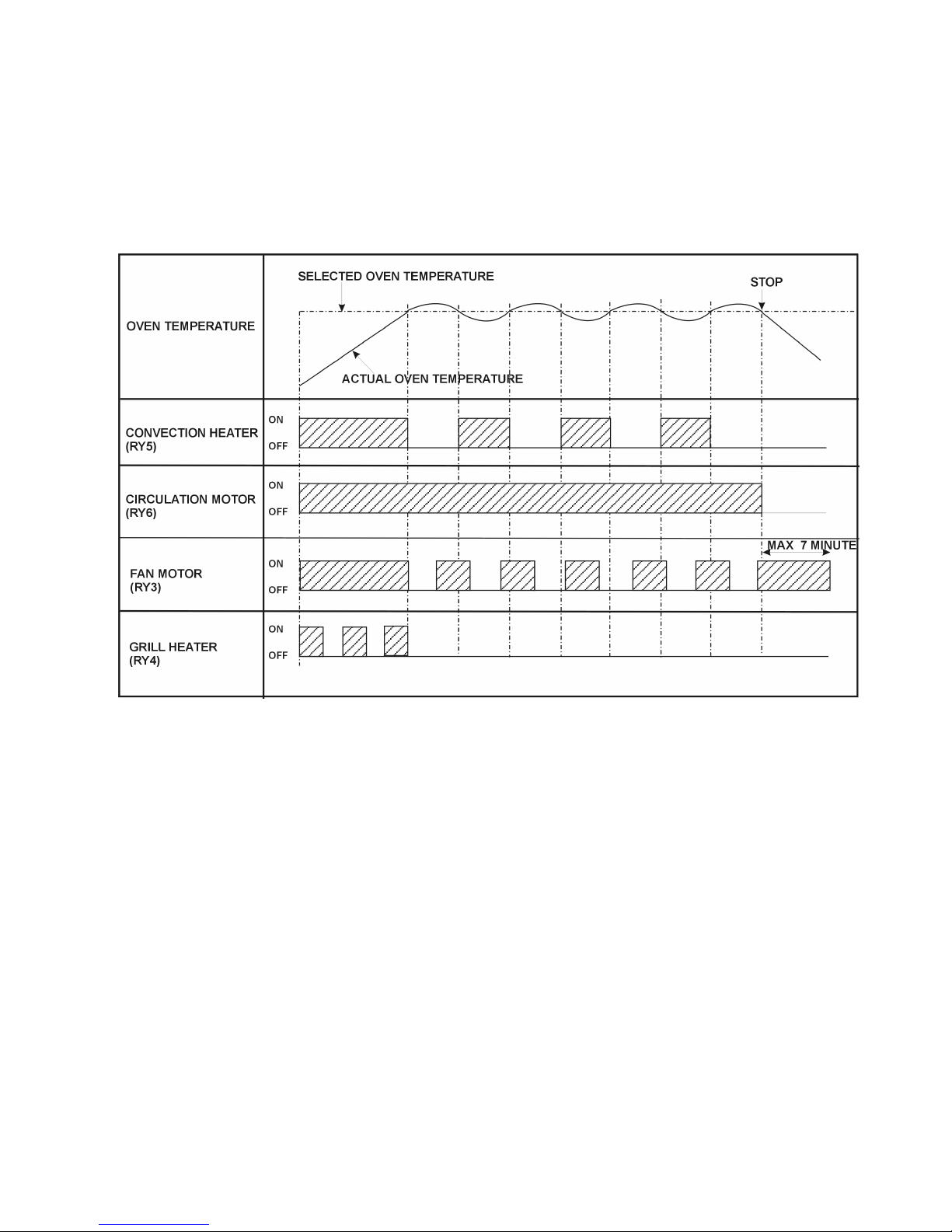
8.4. Convection Cooking
1. The digital programmer circuit operates the power relays
RY3,RY5 and RY6 in the sequence as shown in the figure
below.
2. When the oven reaches a predetermined temperature the
digital programmer circuit stops supplying power to relay
RY5, resulting in the convection heater turning off.
3. When the temperature drops below the predetermined
temperature, the digital programmer circuit supplies
power to power relay RY5 resulting in the convection
heater turning on.
Note: After the convection process, if the oven temperature is higher than the predetermined temperature, the
fan motor rotates to cool the electronic components and
the oven.
Convection Cooking Duty Cycles
Figure 1
Page 12

NN-CT878SBJQ JLFSMWC003 32L OEM
12
8.5. Combination Cooking
Combination cooking is achieved by operating the microwave
and heater modes together during one cooking cycle. There
are three combination modes.
1. Combination (convection and microwave)
2. Combination (grill and microwave)
3. Combination (grill, convection and microwave)
The digital programmer circuit operates the power relays as
shown in the figures below.
When the oven temperature reaches the predetermined temperature, the digital programmer circuit stops supplying power
to relay (RY5) resulting in the convection heater turning off.
During this time the digital programmer circuit continues to
operate relay (RY1) so that microwave activity continues at the
duty cycle selected. The inverter control signal level is also
maintained. The microwave activity continues to cycle until the
entire cooking program is completed.
When the oven temperature drops below the selected temperature, the digital programmer circuit operates power relay (RY5)
switching on the heater elements.
In the case of grill combination the sequence applies with the
digital programmer circuit switching power relay (RY4) to control, the grill elements.
With convection, grill and micro power combination. The grill
elements and convection elements are operated alternatively
whilst the oven temperature is above the selected level.
Convection And Microwave Combination Duty Cycles
Grill And Microwave Combination Duty Cycles
Grill Convection And Microwave Combination Duty Cycles
Convection Heater Micropower
100 - 250 C DISPLAY OUTPUT ON OFF
440 360W 66 0
250 360W 48 18
100 360W 21 45
Grill Heater Micropower
ON OFF DISPLAY OUTPUT ON OFF
Grill 1 51 15 440 360W 66 0
Grill 2 42 24 250 360W 48 18
Grill 3 28 38 100 360W 21 45
Convection
Heater
Grill Heater Micropower
100 - 250 C ON OFF OUTPUT ON OFF
Grill 1 51 15 440 360W 66 0
Grill 2 42 24 250 360W 48 18
Grill 3 28 38 100 360W 21 45
Page 13

NN-CT878SBJQ JLFSMWC003 32L OEM
13
8.5.1 convection and microwave duty cycles
Figure 1
Page 14

NN-CT878SBJQ JLFSMWC003 32L OEM
14
8.5.2 grill and microwave duty cycles
Figure 2
Page 15

NN-CT878SBJQ JLFSMWC003 32L OEM
15
Figure 3
8.5.3 Grill,Convection and microwave duty cycles
Page 16

NN-CT878SBJQ JLFSMWC003 32L OEM
16
8.6. One touch Auto sensor cooking
Auto sensor cook is a revolutionary way to cook by microwave
without setting a power level or selecting a time. All that is necessary is to select an auto sensor program before starting to
cook.
Understanding Auto sensor cooking
As food cooks, a certain amount of steam is produced. If the
food is covered, this steam builds up and eventually escapes
from the container. In auto sensor cooking, a carefully designed
instrument, called the humidity sensor element, senses the
escape of steam. then, based upon the auto sensor program
selected, the unit will automatically determine the correct power
level and the proper length of time it will take to cook the food.
NOTE: Auto sensor cooking is successful with the foods
and recipes found in the auto sensor cooking guide.
Because of the vast differences in food composition, items
not mentioned in the cooking guide should be prepared in
the microwave oven using the power select and time features. Please consult variable power microwave cook book
for procedures.
Explanation of the auto sensor cooking process
1. The shaded columns in figure 1 indicate when the humidity sensor heater is on.
2. During the 30 second period there is no microwave activity. When calculating the T2 time by using the formula
below, make sure this 30 seconds is subtracted from the
T0 time.
3. T1 time T0 time - 30 seconds
4. T2 time when the steam escapes from the cooking container placed in the oven, the humidity sensor detects it
and the microprocessor calculates the balance of cooking
time. This T2 time is then shown in the display and begins
counting down.
Balance of cooking (T2 time)
The balance of cooking time which is called T2 time, can be
calculated by the following formula.
T2 time (in sec.) = T1 time x K factor
NOTE: Remember, the T1 time starts after the start pad is
tapped. The coefficient K is programmed into the microprocessor memory and they are listed in the following
tables along with the P1 and P2 power.
NOTE: When “More“ or “Less” pad is selected, the K factor
varies resulting in T2 time to be increased or decreased.
Calculating the T2 time
Example 1: If the t1 time is measured to be 2 minutes and 40
seconds, and the auto sensor program selected is sensor
reheat. Fish (Program 4)
T2 = T1 x K
= 2 min. and 40 sec. X. 0.3
=48 sec.
Auto sensor cooking
Figure 1
Category P1 POWER P2 POWER K FACTOR
STANDARD
1. Chilled meal HIGH HIGH 1.6
2. Frozen meal MED HIGH 0.9
Page 17

NN-CT878SBJQ JLFSMWC003 32L OEM
17
9 Cautions to Be Observed When Troubleshooting
Unlike many other appliances, the microwave oven is a high
voltage, high current device. Although it is free from danger in
ordinary use, extreme care should be taken during repair.
Caution
Servicemen should remove their watches whenever
working close to or replacing the magnetron.
9.1. Check the grounding
Do not operate on a two wire extension cord. The microwave
oven is designed to be used when grounded. It is imperative,
therefore, to ensure the appliance is properly grounded before
beginning repair work.
9.2. Inverter Warnings
DANGER, HIGH VOLTAGE AND HIGH TEMPERATURE
(HOT/LINE) OF THE INVERTER POWER SUPPLY (U)
This high voltage inverter power supply handles very high
voltage and very high current for the magnetron tube.
Though it is free from danger in ordinary use, extreme care
should be taken during repair. As you can see, it looks like a
TV flyback transformer, however, the current is extremely
large and is therefore, dangerous due to this high current
and high voltage.
The aluminium heat sink is also energized with high voltage
(HOT), so do not touch when the AC input terminal is connected. The power devices (Collector) is directly connected
to the aluminium heat sink.
The aluminium heat sink may be (HOT) due to heat energy,
therefore, extreme care should be taken during servicing.
WARNING FOR INVERTER POWER SUPPLY (U) GROUNDING
Check the high voltage inverter power supply circuit grounding. This high voltage inverter power supply circuit board
must have a proper chassis ground, the inverter grounding
bracket must be connected to the chassis. If the inverter
board is not grounded it will expose very high voltages and
cause extreme DANGER! Be sure that the inverter circuit is
properly grounded via the inverter earth bracket.
HV Inverter warning
Figure 1
Page 18

NN-CT878SBJQ JLFSMWC003 32L OEM
18
WARNING! DISCHARGE THE HIGH VOLTAGE CAPACITORS
For about 30 seconds after the oven is turned off, an electric charge remains in the high voltage capacitors in the
inverter power supply circuit board.
When replacing or checking parts, remove the power plug
from the outlet and short the inverter output terminal of the
magnetron filament terminals to the chassis ground with an
insulated handle screwdriver to discharge. Please be sure
to touch the chassis ground side first and then short to the
output terminals.
WARNING
There is high voltage present with high current capabilities
in the circuits of the primary and secondary windings, choke
coil and heat sink of the inverter. It is extremely dangerous
to work on or near these circuits with the oven energized.
DO NOT measure the voltage in the high voltage circuit
including the filament voltage of the magnetron.
WARNING
Never touch any circuit wiring with your hand nor with an
insulated tool during operation.
Inverter Grounding
Figure 2
Discharging the high voltage capacitors
Figure 3
Page 19

NN-CT878SBJQ JLFSMWC003 32L OEM
19
9.3. When parts must be replaced,
remove the power plug from
the outlet.
9.4. When the 10A fuse is blown
due to the operation of the
short switch:
WARNING
When the 10A 250V fuse is blown due to the operation of
the short switch, the primary latch switch and short switch
must be replaced. It is also important to change the power
relay 1 (RY1) when the continuity test shows shorted contacts.
1. This is mandatory. Refer to “adjustments and measurements” for the location of these switches.
2. When replacing the fuse, confirm that it has the appropriate rating for these models.
3. When replacing faulty switches, be sure the mounting
tabs are not bent, broken or deficient in their ability to hold
the switches.
9.5. Avoid inserting nails, wire etc.
through any holes in the unit
during operation.
Never insert a wire, nail or any other metal object through the
lamp holes on the cavity or any holes or gaps, because such
objects may work as an antenna and cause microwave leakage.
9.6. Confirm after repair
1. After repair or replacement of parts, make sure that the
screws of the oven, etc. are neither loose nor missing.
Microwaves might leak if screws are not properly tightened.
2. Make sure that all electrical connections are tight before
inserting the plug into the wall outlet.
3. Check for microwave energy leakage. (Refer to procedure for measuring microwave energy leakage).
CAUTION MICROWAVE RADIATION
DO NOT BECOME EXPOSED TO RADIATION FROM THE
MICROWAVE GENERATOR OR OTHER PARTS CONDUCTING MICROWAVE ENERGY
IMPORTANT NOTICE
The following components have potentials above 250V
while the appliance is in operation.
• Magnetron
• High voltage transformer (Located on inverter (U))
• High voltage diodes (Located on inverter (U))
• High voltage capacitors (Located on inverter (U))
Pay special attention in these areas.
When the appliance is operated with the door hinges or
magnetron fixed incorrectly, the microwave leakage can
reach more than 5mW/cm
3
. After repair or exchange, it is
very important to check if the magnetron and the door
hinges are correctly fixed.
9.7. Sharp Edges
Caution
Please use caution when unpacking, installing or moving
the unit, as some exposed edges may be sharp to touch
and cause injury if not handled with care.
Page 20

NN-CT878SBJQ JLFSMWC003 32L OEM
20
10 Parts Replacement Procedure
10.1. Magnetron
1. Discharge the high voltage capacitors on the inverter circuit.
2. Remove the five screws shown in figure 1
3. Disconnect the two high voltage leads from the magnetron
4. Remove the four screws holding the magnetron as shown
in figure 2
NOTE: After replacing the magnetron, tighten the mounting screws making sure that there is no gap between the
waveguide and the magnetron to prevent microwave leakage.
Caution
When replacing the magnetron, ensure that the antenna
gasket is in place.
Note
The magnetron used for this model is unique for the inverter
power supply system. Make sure to use the magnetron as
listed in the parts list.
Removal of the magnetron
Figure 1
Page 21

NN-CT878SBJQ JLFSMWC003 32L OEM
21
10.2. Inverter power supply (U)
1. Discharge the high voltage capacitors
2. Unplug the H.V. Lead wires from the magnetron
3. Remove the connector CN701 and CN702 from the
inverter PCB
4. Remove the two screws holding the inverter base to the
chassis (See figure 3)
5. Remove the one screw holding the inverter earth wire to
the oven chassis.
6. Carefully remove the inverter PCB and support base from
the oven.
7. Remove the air guide E by un-clipping the catch hooks
8. Remove the four screws holding the PCB to the inverter
support base.
Caution when replacing the inverter power supply (U)
1. Make sure that grounding plate is in place
2. Securely tighten the grounding screw through the side of
the chassis (Base).
3. Securely connect the 3 lead wire connectors
4. Make sure that the heat sink has enough space (gap)
from the oven. Take care not to touch any lead wire to the
aluminium heat sink because it is hot.
Screws to remove the magnetron
Figure 2
Removal of the inverter PCB
Figure 3
Page 22

NN-CT878SBJQ JLFSMWC003 32L OEM
22
10.3. Digital Programmer Circuit
(DPC) and membrane key
board.
NOTE: Ground any static electric built up on your body before
handling the DPC.
1. Disconnect all connectors from the DPC.
2. Remove the four screws holding the escutcheon base
and slide the escutcheon base upward slightly. removal is
easier with the door open.
3. Release the flat cable.
4. Remove the six screws holding the DPC DU assembly
5. Remove the door lever
6. Remove the nine screws holding the DPC AU assembly
To remove escutcheon pad
1. Remove the escutcheon bracket from the escutcheon
base by freeing the 4 catch hooks on the escutcheon
base.
2. Peel away the display window from the inside of the base.
3. Remove the membrane assembly by pushing from the
inside of the base and then peeling away from the outside
surface.
NOTE:
1. The escutcheon key board is attached to the escutcheon
base with double faced adhesive tape. Therefore, applying hot air such as using a hair dryer is recommended for
smoother removal
2. When installing a new escutcheon key board, make sure
that the surface of the escutcheon base is cleared sufficiently so that problems such as, shorted contacts and
uneven surfaces can be avoided.
10.4. Low voltage transformer and/
or power relays
Note
Be sure to ground your body to discharge any static
before handling the DPC.
1. Using a solder wick or a de soldering tool and a 30W soldering iron, carefully remove all solder from the terminal
pins of the low voltage transformer and/or power relays.
2. With all of the terminal pins cleaned and separated from
the DPC contacts, remove the defective transformer/
power relays and install the new components making
sure that the terminal pins are inserted completely. Carefully re solder all terminal contacts carefully.
Note
Do not use a soldering iron or de soldering tool of more
than 30 watts on DPC contacts
Disconnecting the PCB lock connector
Figure 4 Removal of DPC DU and DPC AU
Figure 5
Page 23

NN-CT878SBJQ JLFSMWC003 32L OEM
23
10.5. Fan Motor
1. Disconnect the two lead wires from the fan motor terminals
2. Remove the power cord by removing the two wires from
the noise filter and the ground connection from the oven
chassis.
3. Remove the noise filter
4. Remove the two screws holding the orifice assembly
5. Remove the two screws holding the fan motor assembly
6. Detach the orifice assembly and the fan motor assembly
from the oven assembly.
7. Remove the fan blade from the fan motor by pulling outward.
10.6. Door disassembly
1. Remove door C from door E by carefully pulling outward
starting from the upper right hand corner using a flat
blade screwdriver.
2. Remove four screws holding the door E to the door A
assembly
3. Replace the door A and screen B as a complete unit.
4. Remove the door key and spring from the door E
After replacement of the defective component parts of the
door, reassemble it and follow the instructions below for
proper installation and adjustment so as to prevent excessive microwave leakage.
1. When mounting the door to the oven, be sure to adjust
the door parallel to the bottom line of the oven face plate
by moving the upper hinge in the direction necessary for
proper alignment.
2. Adjust so that the door has no play between the inner
door surface and the oven front surface. if the door
assembly is not mounted properly, microwave power may
leak from the clearance between the door and oven.
3. Perform the microwave leakage test.
10.7. Turntable Motor
1. Remove the motor cover by breaking off at the 8 spots
indicated by the arrows.
2. Disconnect the two lead wires connected to the turntable
motor
3. Remove the turntable motor by removing the two screws
Removing the fan motor
Figure 6
Disassembly of the door
Figure 7
Page 24

NN-CT878SBJQ JLFSMWC003 32L OEM
24
Note: After breaking off the motor cover, make sure that
cut-off portions are properly trimmed off or bent inside so
that no sharp edges are exposed.
Note: To secure the motor cover use a 4 x 6 screw.
10.8. Quartz Heater
1. Remove the sensor cable from the DPC connector CN7.
2. Remove the exhaust guide A by removing the two screws
shown in figure 10.
3. Disconnect the cables to the grill heater
4. Remove the grill cover by removing the 5 screws in figure
11
5. Remove the two screws holding the grill heater
(Figure12).
6. Loosen the 2 screws holding the ceramic grill holders,
turn the holders to release the grill element.
7. Remove the heater bracket D by using a flat blade screw
driver to lever back the tabs.
8. The grill element can now be removed from inside the
oven.
Removing the exhaust guide and grill cover
Figure 10
Removing the Turntable motor cover
Figure 8
Two screws to remove the turntable motor
Figure 9
Page 25

NN-CT878SBJQ JLFSMWC003 32L OEM
25
Removing the screws holding the grill heater
Figure 11
Removing the grill element
Figure 12
Page 26

NN-CT878SBJQ JLFSMWC003 32L OEM
26
10.9. Convection Element And Circulation Fan Motor
1. Remove one screw to remove the exhaust guide D. Figure 13.
2. Remove the rear heater cover by removing the three screws. Figure 13
3. Remove the temperature sensor by removing the two screws. Figure 14
4. Remove the power cord.
5. Remove the wire terminals from the circulation fan motor and the convection heater element.
6. Remove the four screws from the oven base. Figure 15
7. Carefully place the oven onto its base and remove the backplate.
8. Remove the nut holding the circulation fan. Figure 16
9. Remove the circulation fan by removing the three screws. Figure 16
10. Remove the convection element by removing the two screws. Figure 16
Removing the rear heater cover
Figure 13
Page 27

NN-CT878SBJQ JLFSMWC003 32L OEM
27
Removing the oven back plate
Figure 14
Removing the base plate
Figure 15
Page 28

NN-CT878SBJQ JLFSMWC003 32L OEM
28
Removing the circulation motor
Figure 16
Page 29

NN-CT878SBJQ JLFSMWC003 32L OEM
29
11 Component Test Procedure
Caution
1. High voltage is present at the high voltage terminal of the
inverter unit, including the aluminium heat sink.
2. It is not necessary or advisable to attempt to measure this
high voltage.
3. Before touching any oven components, or wiring, always
unplug the oven from its power source and discharge the
high voltage capacitors.
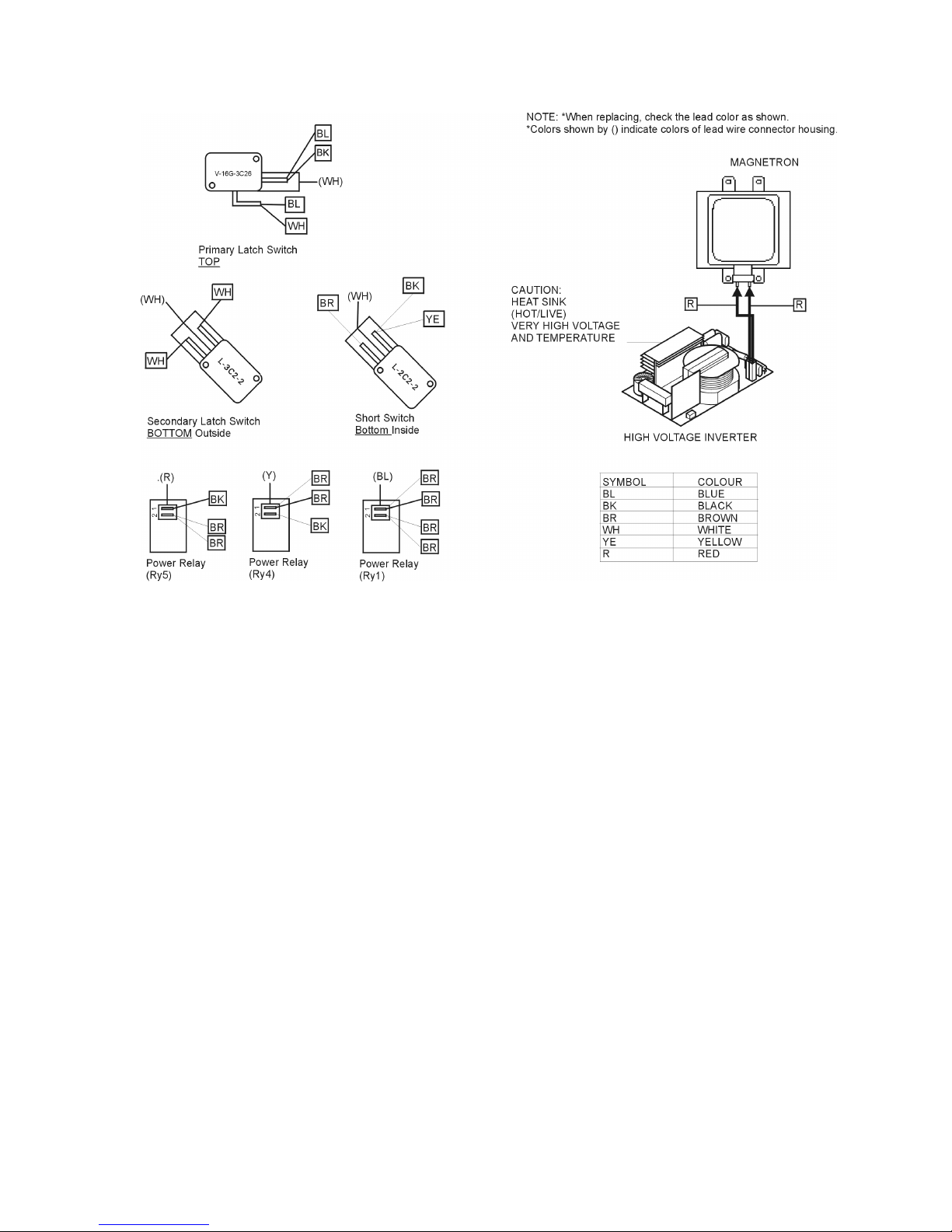
11.1. Primary Latch Switch, Secondary Latch Switch and power
relay B interlocks.
1. Unplug the lead connectors to power relay B and verify
the continuity of the power relay B 1-2 terminals.
2. Unplug the lead connectors to the primary latch switch
and secondary latch switch.
3. Test the continuity of the switches with the door open and
closed with an ohm meter on the lowest scale.
Normal continuity readings should be as followed.
11.2. Short Switch and Monitor Circuit
1. Unplug the lead wires from the HV inverter primary terminals.
2. Connect the test probes of the ohm meter to these leads
3. Test the continuity of the short switch with the door open
and the door closed using the lowest ohm scale.
11.3. Magnetron
Continuity checks can only indicate an open filament or a
shorted magnetron. To diagnose an open filament or shorted
magnetron.
1. Isolate the magnetron from the circuit by disconnecting
the HV leads
2. A continuity check across the magnetron filament terminals should indicate one ohm or less
3. A continuity check between each filament terminal and
the magnetron case should read open.
11.4. Push Button Keyboard
Check the continuity between the switch terminals, by tapping
an appropriate pad on the keyboard. The keypad matrix is
shown on Page 50.
Door Open Door Closed
Primary Latch Switch infinite Ω(Open) 0Ω (Close)
Secondary Latch
switch
infinite Ω(Open) 0Ω (Close)
Power relay B infinite Ω(Open) infinite Ω (Close)
Door Open Door Closed
Monitor switch 0Ω
infinite Ω
Page 30

NN-CT878SBJQ JLFSMWC003 32L OEM
30
11.5. Inverter Power Supply
Caution
DO NOT try to repair this inverter power supply. Replace as a whole H.V. Inverter Unit.
Inverter power supply diagram
Figure 3
11.6. Inverter Power Supply Unit
Warning
Do not attempt to make any measurements in the high voltage circuitry of the inverter or magnetron.
See troubleshooting of the inverter circuit and magnetron on
page 27 to determine if the inverter power supply is still functioning.
11.7. Temperature Sensor
A temperature sensor is mounted on the rear of the oven. The
resistance reading across the thermistor should read 300K ohm
within a temperature range of 10 to 30 degrees centigrade. This
would be the temperature range within a kitchen environment.
If the resistance measured is outside this range the thermistor
is defective and should be replaced.
NOTE: When measuring the resistance of the thermistor disconnect the connector from the digital programmer circuit.
NOTE: If the microwave oven has been operated allow to cool
to room temperature before attempting to measure the thermistor resistance.
11.8. Humidity sensor and digital
programmer circuit.
1. Check the resistance across the sensor heater terminals.
Normal cold resistance should read approximately 4.5
ohms.
2. Check the voltage across the sensor heater terminals. It
should read approximately 2.5VDC
3. In order to determine if the auto cooking by humidity sen-
sor is working, perform the following test.
1. Place a water load (150cc) in the oven.
2. Press the auto reheat panel.
3. Press the start pad
4. The humidity sensor detects steam about 2 to 4 minutes
after the start pad has been pressed.
5. The auto cooking (T1) automatically switches to cooking
time. (T2)
6. The remaining cooking time T2 appears in the display
window. If 48s -1min 36 secs appears in the display, the
humidity sensor function is normal.
Page 31

NN-CT878SBJQ JLFSMWC003 32L OEM
31
12 Measurements and Adjustments
Warning
• For continued protection against radiation hazard, replace
only with identical parts.
• When the 10 amp fuse is blown due to the operation of the
short switch, you must replace the primary latch switch and
short switch. Then follow the installation procedures below.
• Interlock switch replacement - In replacing faulty switches,
be sure mounting tabs are not bent, broken or otherwise
deficient in their ability to hold the switches.
• Refer to the schematic and wiring diagram to ensure proper
connection
12.1. Installation of primary latch
switch, secondary latch switch
and short switch.
1. When mounting the primary latch switch, secondary latch
switch and short switch to the door hook assembly. Follow the instructions in figure 1.
NOTE: No specific adjustment during the installation of
each switch into the door hook is necessary.
2. When mounting the door hook assembly to the oven
assembly, adjust the door hook assembly by moving it in
the direction of the arrow in figure 1. Ensuring the door
does not have any play in it. Check for play by pulling the
door assembly. Make sure that the latch keys move
smoothly after adjustment is completed. Completely
tighten the screws holding the door hook assembly to the
oven assembly.
3. Reconnect the short switch, primary switch and secondary latch switches and check the continuity of the monitor
circuit and latch switches by following the component test
procedures on page.
12.2. Measurement of microwave
output
The output power of the magnetron can be determined by performing the IEC standard test. However, due to the complexity
of the IEC test procedures, it is recommended to test the magnetron using the simple method outlined below.
Necessary equipment:
• 1 litre beaker
• Glass thermometer
• Wrist watch or stop watch
NOTE: Check the line voltage under load. Low voltage will
lower the magnetron output. Take the temperature readings
and heating time as accurate as possible.
1. Fill the beaker with exactly one litre of tap water. Stir the
water using the thermometer and record the beakers temperature (Recorded as T1)
2. Place the beaker on the center of the glass cook plate.
3. Stir the water again and read the temperature of the beaker (Recorded as T2)
4. The normal temperature rise at the high power position
for each model is shown in the table. (Figure 2)
Adjustment of latch switch assembly
Figure 1
TABLE (1L - 1min test)
RATED OUTPUT TEMPERATURE RISE
1000W 8°C
Page 32

NN-CT878SBJQ JLFSMWC003 32L OEM
32
13 Troubleshooting Guide
Page 33

NN-CT878SBJQ JLFSMWC003 32L OEM
33
Fuses are not blown
Fuses are blown
Page 34

NN-CT878SBJQ JLFSMWC003 32L OEM
34
6A5BPQ
Other problems
Inverter circuit troubleshooting
6A5BPQ
Alternative method for toubleshooting, the inverter circuit
Page 35

NN-CT878SBJQ JLFSMWC003 32L OEM
35
14 Digital Programmer Troubleshooting Guide
Page 36

NN-CT878SBJQ JLFSMWC003 32L OEM
36
Page 37

NN-CT878SBJQ JLFSMWC003 32L OEM
37
15 Description of Operating instruction
15.1. Auto weight defrost, Auto
weight Cook
When an auto control feature is selected and the start pad
pressed:
1. The digital programmer circuit determines the power level
and the cooking time and indicates the operating state in
the display. The table shows the corresponding cooking
times for each category and its respective weight.
2. When the cooking time in the display window has
elapsed, the oven turns off automatically via the control
signal from the digital programmer circuit.
Note: After auto cooking if the oven temperature is
over the predetermined temperature the fan motor
rotates to cool the oven and its components.
Auto Weight Defrost
Category 1st Touch Weight Cooking Time
Bread 100g 45s
Meat Items 200g 3m 40s
Meat Joints 400g 6m 20s
Category 1st Touch Weight Cooking Time
Whole Chicken 1000g 18m 20s
Chicken Portions 300g 10m 00s
Beef / Lamb 500g 14m 40s
Casserole 800g 56m 40s
Chilled Crispy Top 300g 10m 00s
Frozen Crispy Top 300g 14m 00s
Pastry 600g 15m 00s
Cake 400g 11m 40s
 Loading...