

Mail: P.O. Box AA631
Evanston, IL 60204 USA
Ship: 1728 Brummel St.
Evanston, IL 60202 USA
THE JOHN HARDY COMPANY
Phone: 847-864-8060
Toll-free: 866-379-1450
Fax: 847-864-8076
www.johnhardyco.com
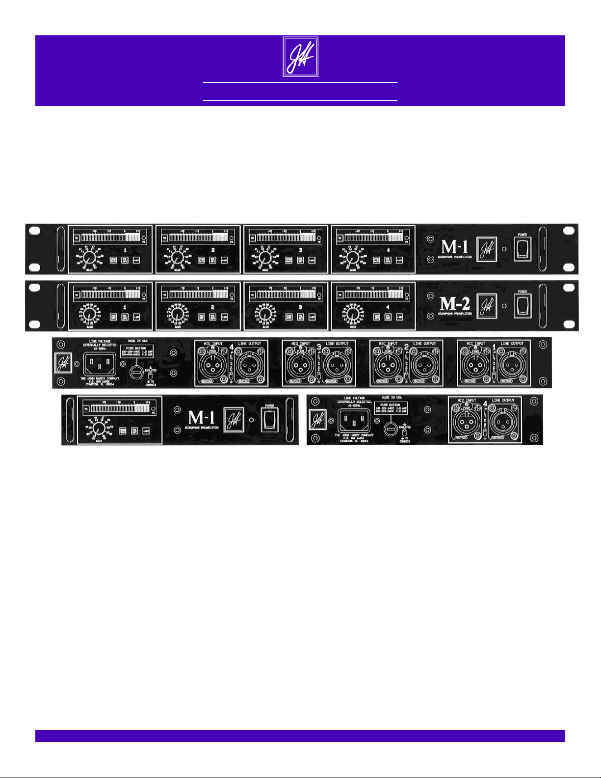
M-1 Mic Preamp
October 6, 2003
M-2 Mic Preamp
M-1 Personal Mic Preamp
The M-1, M-2 and M-1 Personal mic preamps are among the finest mic preamps in the world. They provide the accuracy
and transparency that is missing in other mic preamps. No matter what your application, they will provide superior
results. The world's best input transformer (Jensen JT-16-B), best op-amp (990C discrete class-A op-amp) and the
elimination of all coupling capacitors from the signal path combine to provide the highest performance.
The M-1 and M-2 have a 19” wide rack-mount chassis (1.75”H x 19”W x 8”D) and can be ordered with one, two, three or
four channels. The M-1 Personal mic preamp has an 8” wide chassis with a capacity of one channel. There are two meter
options, and the best Jensen output transformer (JT-11-BMQ) is available as an option. These options and basic channels
can be easily added later.
The M-1 was introduced in 1987. The M-2, introduced in 1996, is a variation of the M-1. The first difference is the gain
controls: The M-1 has a two-section gain-pot providing continuously variable adjustment in two overlapping ranges of 12
to 40dB and 32 to 60dB. The “HIGH GAIN” switch changes ranges. The M-2 has a 16-position gain-switch with 1%
metal-film resistors, providing accurate and repeatable gain-settings from 15 to 60dB in steps of 3dB.
Further differences involve the push-button switch to the right of the gain-pot or gain-switch. The M-1 has a “HIGH
GAIN” switch as mentioned above. Since this switch is not required in the M-2, the p.c. board layout was modified to
allow that switch to be used in the M-2 as either a “20Ω MIC” switch, or a “20dB PAD” switch, depending on how the
board is assembled. The 20Ω MIC switch provides optimum matching of microphones with extremely low output
impedances. The 20dB PAD switch attenuates the input signal by 20dB prior to the JT-16-B input transformer, providing
a maximum input level of +29dBu.
1

Highlights
The Jensen JT-16-B Input Transformer is
Jensen's best mic-input model. Jensen is
known worldwide for their superior audio transformers. If you thought transformers were a compromise, you haven't
heard the JT-16-B!
The JT-16-B is a large, low impedance
ratio (150:600Ω) transformer made with
a proprietary 80% nickel (nickel-ironmolybdenum) core material. The large
size allows it to handle extremely high
signal levels of +12dBu at 30Hz and
above, +8dBu at 20Hz. The low ratio
provides less distortion, flatter frequency
response and more linear phase response
than more typical high-ratio transformers
(150:15kΩ). The proprietary 80% nickel
core material is far superior to, and much
more expensive than the steel often
found in other transformers.
The JT-16-B outperforms transformerless mic preamps because it eliminates
the input coupling capacitors that are required with transformerless designs. Capacitors degrade the audio signal because they have a property known as dielectric absorption, where some of the
signal passing through the capacitor is
absorbed by the dielectric of the capacitor, then released a short time later. This
smears the signal. Transformerless designs require these capacitors to keep the
phantom supply voltage from reaching
the circuitry of the preamp. Transformers inherently block DC voltages, eliminating the need for the capacitors.
The JT-16-B provides better common
mode rejection than transformerless designs, important in electrically noisy environments. It handles common mode
voltages as high as ±300V peak. Transformerless designs are usually limited to
maximum voltages equal to their power
supply voltages, typically ±15V to ±18V.
The 990 Discrete Op-Amp is faster, quieter, more powerful and better sounding
than the typical monolithic op-amps
found in other equipment. Each individual (discrete) transistor, resistor, diode,
capacitor and inductor of the 990 has
been carefully chosen for its task. This
provides a level of performance that is
not possible in a monolithic op-amp
where all components are fabricated on
the same tiny chip of silicon. The 990
operates from ±24V power supplies, al-
lowing output levels of greater than
+24dBu. It can drive long cables and
loads as low as 75Ω, something monolithic op-amps cannot do. See the 990
data package for further information.
Elimination of All Coupling Capacitors
from the Signal Path results in less degra-
dation of the audio signal. Two superior
techniques are used to accomplish this:
1. Input bias current compensation circuitry nulls out the small DC currents
(thus voltages) that flow from the inputs
of the 990 (or any op-amp), voltages that
could cause noise when operating the
gain controls. This circuitry also reduces
the DC offset voltage at the output of the
990. Most other mic preamps use coupling capacitors to block the input bias
currents, resulting in signal degradation.
2. DC servo circuitry nulls out the DC
offset voltage at the output of the 990,
eliminating the need for a traditional output coupling capacitor to block that voltage. The signal degradation caused by
that capacitor is also eliminated. See the
schematic on page 7 for details.
M-1: Dual Range Gain Control and “HIGH
GAIN” Switch. The overall gain adjust-
ment range is 12 to 60dB, a span of
48dB. Rather than cover the entire 48dB
in one revolution of the gain pot, there
are two smaller, overlapping ranges selected by the “HIGH GAIN” switch. The
low gain range provides adjustment of
12 to 40dB, the high gain range 32 to
60dB. This provides 28dB of adjustment
per range, with 8dB of overlap. The relatively small 28dB of adjustment per
range provides great feel and resolution,
with sufficient overlap to keep you “in
range” at all times.
There are two reasons for the great feel:
First, with fewer dB of adjustment per
revolution, it is easier to adjust the pot to
the desired gain setting. The second reason is a more technical one, and very important. A single 10kΩ pot covering the
entire 48dB range in a single revolution
could get a bit “touchy” as it approached
the maximum gain point (minimum resistance), due to contact resistance variation (CRV). The gain pot of the M-1 is
actually a two section pot having a 10kΩ
section and a 500Ω section. In high gain
Standard Features
applications where CRV would be a
problem with a 10kΩ pot, the 500Ω section of the pot is used. CRV is reduced
by a factor of twenty, virtually eliminating any touchiness. See page 5 for details.
The unusually low minimum gain of
12dB allows the M-1 to handle input levels as high as +12dBu before the output
is driven past its +24dBu maximum output level. The JT-16-B input transformer
can handle input levels of +12dBu at
30Hz and above, and +8dBu at 20Hz.
If you need infinite resolution so you can
set the mic preamp to any gain, or have
the ability to “ride gain” during a performance, the gain controls of the M-1 are
ideal.
M-2: 16-Position Rotary Gain-Switch with
1% metal-film resistors provides accurate
and resetable gain control from 15 to
60dB in steps of 3dB. For situations
where quick and exact gain-matching of
channels or exact resettability is required, the gain controls of the M-2 are
ideal.
M-2: “20Ω MIC” Switch provides optimum
matching with microphones that have a
20Ω output impedance. Note that the
Jensen JT-16-B mic-input transformer
does exceptionally well with just about
any low-impedance microphone, including those with a 20Ω output impedance,
but this switch provides further refinement. The switch takes the place of the
“HIGH GAIN” switch of the M-1.
M-2: “20dB PAD” Switch provides a 20dB
resistive pad before the input transformer. This increases the maximum input level to +29dBu for situations where
excessively high input levels are encountered. Most applications won't need a
pad, but for those that do, this option
provides it. This switch takes the place
of the “HIGH GAIN” switch of the M-1.
Note that you can get an M-2 channel
built with the “20Ω MIC” option or the
“20dB PAD” option, but not both. These
options take advantage of the fact that
the “HIGH GAIN” switch of the M-1 is
not needed in the M-2, and the p.c. board
was modified to allow that switch to be
used one of three ways.
2

M-1 and M-2 Common Features:
Polarity Reverse Switch (“POL REV”) re-
verses the signal polarity at a point immediately before the input transformer.
48V ON/OFF Switch (“+48V”) for phantom
power. The phantom supply has more
than enough current to handle any condenser microphone.
All Front Panel Switches are LED Illuminated. A custom clear plastic push button
was developed for the M-1 and M-2.
Each button's function is marked on the
front surface and is illuminated dimly
when off, brightly when on, each button
with its own LED color. The HIGH
GAIN switch of the M-1 (20Ω MIC or
20dB PAD for the M-2) uses a red LED,
the POL REV switch uses an amber
LED and the +48V switch uses a green
LED. No guessing about these switches!
Gold Plated XLRs for maximum reliability. Gold does not tarnish or oxidize. Silver plated XLRs are available on special
order.
Ground Lift Switch on Each Channel allows disconnection of the shield (pin 1)
of the output XLR. This can be helpful
in eliminating ground loops. This minitoggle switch is on the rear panel.
Toroidal Power Transformer with additional silicon-iron shielding eliminates
hum problems caused by stray magnetic
fields. Some manufacturers use a separate power supply chassis and umbilical
cord to keep the power transformer's
stray magnetic fields from interfering
with the audio circuitry. In the M-1 and
M-2, the stray magnetic fields are controlled at the transformer. Each transformer is carefully tested for stray magnetic fields under worst-case full-load
conditions. The optimum rotational position is determined, then the silicon-iron
shielding is added to assure hum-free
performance. Thanks to these extra details, the transformer can be built into the
M-1 or M-2 chassis. No separate chassis
and umbilical cord to deal with.
Toroidal power transformers inherently
have lower stray magnetic fields than
conventional EI-core transformers. They
are also smaller and lighter. They are
also much more expensive!
Universal Power Supply. An internal
switch provides six primary voltage
choices: 100, 120, 140, 200, 220 and 240
volts. The power cord is detachable, with
a line filter included in the input connector. These features allow the preamps to
be easily adapted for use anywhere in the
world. The supply accommodates
over/under voltage situations easily.
Chassis Ground Isolation Switch allows
the chassis ground to be isolated from
the signal ground, or tied to it. This can
be helpful in eliminating ground loops in
certain situations. This mini-toggle
switch is on the rear panel.
Built to Order, the way YOU want it. Start
with only one basic channel if you wish.
Additional channels, meters and output
transformers can be easily field-installed.
The mainframe is ready for all four
channels, with blank panels provided for
unused channels. Have it your way!
VU-1 Meter Card is a very accurate and informative meter that directly monitors the
output level of the MPC-1 mic preamp
card. There is no need to monitor the input
level of the MPC-1 because the output will
clip before the input transformer saturates.
The VU-1 provides a 20 segment LED bargraph display and separate "peak" LED (labeled “PK” on the front panel) to indicate
extremely high signal levels. An LED-illuminated front panel switch (green LED)
gives a choice of “Peak” or “VU” meter
ballistics. The “Peak” ballistic provides a
fast attack time for the bargraph so that
transients are fully indicated. The “VU”
ballistic provides a slower attack time, similar to a standard mechanical VU meter.
The meter scale accurately covers -28 to
+10dB in linear steps of 2dB (15 yellow
LEDs, 5 red LEDs). Easy calibration of the
meter's 0VU operating level is accomplished by moving an internal plug-in
jumper to one of four positions: 0dBu,
+4dBu, +8dBu or Adjustable (the adjustable position covers -10 to +12dBu via
a 25-turn trim pot). Standard setting is
“+4” (0VU on the meter scale equals a
+4dBu output level).
The firing point of the separate peak (PK)
LED is calibrated via a 25-turn trim pot for
output levels of 0 to +22dBu. The standard
Options
setting of +22dBu provides at least 2dB of
warning prior to clipping. Jumpers are provided to choose BAR mode (cumulative
LEDs) or DOT mode (one LED at a time)
for the display.
Circuitry includes a full-wave rectifier,
peak detector, Peak and VU ballistics, and
a temperature compensated log/linear converter. The circuitry is DC coupled and
uses high-speed, precision op-amps with
extremely low DC offset voltage and drift
(better op-amps than you find in the signal
path of many consoles!). All of these features guarantee accurate performance over
a wide temperature range, and for years to
come. On-card voltage regulation for the
op-amp power supplies, and isolated
grounding for the 5 volt LED power supply
assure that the VU-1 will not interfere with
the mic preamp circuitry.
PK-1 Meter Card provides a peak LED function only. It uses the same full-wave rectifier, peak detector, 25-turn trim pot for firing
point calibration, on-card voltage regulation and isolated grounding for the 5 volt
LED power supply that is used on the VU1 card.
JT-11-BMQ Output Transformer is the best
Jensen line-output transformer. It compliments the outstanding line driving capabili-
ty of the 990 by providing a balanced,
floating, isolated output. Ground loop
problems are eliminated because the signal
is coupled magnetically rather than directly, something that transformerless circuits
cannot do. Your application may not require an output transformer, but if you need
one, the JT-11-BMQ is the best.
PIN 2 or PIN 3 HIGH? There are two polarity
standards in use today for XLR connectors.
The official IEC, SMPTE and AES standards state that pin 2 is high (relative to pin
3), while the unofficial standard states that
pin 3 is high (relative to pin 2). The M-1
and M-2 make it very easy to deal with
this. A pair of plug-in jumpers is located
next to each XLR, allowing you to quickly
change from “PIN 2 HIGH” to “PIN 3
HIGH”, or vice-versa. It is very important
to verify the polarity of the equipment that
will be used with the mic preamp, and to
maintain correct polarity when connecting
the mic preamp. Possible problems range
from an audible change due to an inadvertent reversal of polarity, to slight degradation of the signal if a transformer-coupled
output is driving an unbalanced input of
the opposite polarity, to possible damage to
the 990 in a direct-output configuration
driving an unbalanced input of the opposite
polarity (driving a short-circuit!). Please
specify PIN 2 HIGH or PIN 3 HIGH!
3

A few Important Details
Factory Selection of Critical Parts. R2 and
R3, the 6.81kΩ resistors in the phantom
supply network, are matched to 0.1% tolerance for the best performance.
1% 100ppm Metal Film Resistors are
used instead of the more common 5%
200ppm carbon film resistors. They
provide greater initial accuracy, better
long term stability, and higher stability at extremes of temperature.
Polycarbonate Capacitors are used in critical timing circuits instead of cheaper mylar or polyester capacitors. They are much
more stable, and have a more linear
impedance, important parameters in timing circuits such as the ballistics circuits
of the meter cards.
Electrolytic Capacitors with a 105°C Temperature rating are used instead of the
more common 85°C rated parts. This
higher temperature capability means that
they will last much longer than the lower
rated parts. They will also have better,
more linear performance over a wider
temperature range. Electrolytic capacitors
are more failure prone than most other
components (a good thing to remember
when troubleshooting older equipment).
Sometimes they allow small amounts of
DC current to pass through (leakage current), causing pots and switches to be
noisy when operated. (NOTE: in the M-1
and M-2 there are no capacitors in the signal path, so this problem cannot exist).
Other capacitors will short-circuit, or lose
most of their capacitance. Whatever the
failure mode, you have a problem, even in
equipment that never approaches an operating temperature of 85°C. But not with
these mic preamps!
XLR Connectors are Soldered Directly to
the P.C. Card, minimizing the number of
interconnections for better reliability and
better sound quality.
Fully Sealed Potentiometer and Trim Pots
for long, trouble-free life.
Central Point Grounding and Power Distribution. Rather than use a “motherboard”,
wiring harnesses are used to deliver power
supplies and grounds to each channel individually. This provides the least interaction between channels.
The KNOB. A knob is a basic device that
should provide three basic things:
1. Good VISUAL indication of setting.
2. Good TACTILE indication of setting.
3. Good TRACTION for your fingers.
Most knobs don't meet all three of the requirements. Some don't meet any of the
requirements! In addition to these basic
requirements, a knob should look good
and feel good.
Plastic knobs look like . . . well . . . plastic
knobs! Plain round knobs don't give any
tactile indication of which way they are
pointing. Knobs with pointers or bars
sticking out do tell by feel which way they
point, but the protrusion is often so big
that it gets in the way. Some knobs have
an indicator line on top, but the typical
decorative metal finish causes light reflections from the top like spokes of a wheel.
Which is the indicator line and which are
the spokes?
This knob was developed to meet all requirements. It is machined out of solid
aluminum, with a nonreflective black anodized finish. A laser-cut white ceramic
insert is added to create visual and tactile
indication of the knob's setting. The insert
appears as an indicator line on the top of
the knob, and protrudes just enough
(.025”) beyond the side of the knob so that
you can feel it, yet it doesn't get in the
way. Traction is provided by a fine diamond knurl with sharp, fully formed teeth.
The diamond knurl provides traction for
rotary motion, and for vertical motion to
keep your fingers from slipping “up” and
off of the knob. Straight knurls can only
provide rotary traction. Also, there is a
certain amount of tradition in a diamond
knurl. The knob looks great, feels great,
and works great!
An Extruded Aluminum Chassis was developed for the front, rear and sides of the M1 and M-2 chassis. It solves a number of
packaging problems, providing a neater,
stronger and more efficient package. The
brushed and black anodized finish looks
great, and provides optimum thermal
emission properties. Rack-handles are provided for easy installation and handling.
Stainless steel threaded inserts are used
for long life and the ability to withstand
repeated assembly & disassembly. Rackmount handles are provided for ease of
handling.
CONDENSED SPECIFICATIONS (0dBu = 0.775V)
E.I.N., 20-20kHz unweighted, 150Ω source: -129 dBu
Maximum input level, M-1 >30Hz: +12 dBu
Maximum input level, M-2 >30Hz: +9 dBu
Maximum input level, M-2 with pad >30Hz: +29 dBu
Maximum output level at 990 outpu t 75Ω load: +24 dBu
CMRR 100Hz: 100 dB
Deviation fro m linear phase 20Hz-120kHz: <2 deg
THD, JT-16-B, (below saturation) 20Hz 0.036 %
THD, JT-16-B & 990:
60dB gain, 10kΩ load, +2 4dBu output 10kHz: 0.005 %
40dB gain, 600Ω load, +24dBu output 10kHz: 0.003 %
40dB gain, 75Ω load, +24dBu output 10kHz: 0.030 %
DC offset <100 µV
0Ω source: -132 dBu
10kHz: 80 dB
30Hz: 0.022 %
50Hz: 0.010 %
1kHz: 0.003 %
1kHz: 0.004 %
1kHz: 0.003 %
1kHz: 0.005 %
4

Contact Resistance and Contact Resistance Variation
The most familiar specifications for potentiometers are: resistance value, tolerance
and taper. Even these simple specs will
vary with temperature, time, applied voltage, number of rotations, etc., but they are
pretty straight forward. However, contact
resistance (CR), and contact resistance
variation (CRV), are specifications that
are unfamiliar to many people.
A pot has a moving contact, or “wiper”,
and it is positioned along the surface of a
resistance element. The key to understanding the problems of CR and CRV is to realize that the resistance element has a
small but measurable thickness to it, and
the current flow is not always occurring
exactly at the surface of the element. This
is because the current flow follows the
path of least resistance created by the imperfect blend of conductive and non-conductive materials used to make the element. There is a measurable amount of
distance, therefore resistance, between the
contact and the nearest point of current
flow. This contact resistance (CR) can be
as much as 2% of the pot's resistance value, and will vary as the contact is moved
from one position to the next (CRV). If
the current is flowing near the surface of
the element at the contact position, CR is
low. If the current is flowing far below the
surface at the contact position, CR is high.
For example, if the pot measured exactly
10kΩ from end to end, and if you could
find the exact electrical midpoint of the resistive element, it could measure 5200Ω
from either end to the contact sitting at the
midpoint. It takes 5000Ω to get to the
midpoint of the resistive element, and an
additional 200Ω to get to the surface of
the element where the contact is, assuming
a worst-case CR of 200Ω.
When a pot is used as a rheostat, as it is in
the gain control of the MPC-1 mic preamp
card, the CR must be added to the basic
element resistance when making gain calculations. The gain pot of the MPC-1 card
is configured so that a reduction of resistance causes an increase of gain.
For the following example let's assume a
single section 10kΩ pot is used, covering
the entire 48dB adjustment range (12 to
60dB) in a single revolution. Due to the
logarithmic nature of audio, it takes almost a 2kΩ reduction of resistance (10kΩ
to 8kΩ) to provide a 1dB increase of gain
when going from 12 to 13dB of gain,
while it takes a mere 10Ω reduction of resistance (70 to 60Ω) to provide a 1dB increase when going from 47 to 48dB of
gain. The worst-case CR of 200Ω (2% of
a 10kΩ pot) would be insignificant in the
first instance (resistance change from
10kΩ to 8kΩ for a gain change of 12 to
13dB), since a CR of 200Ω is small compared to the 2kΩ change in gain pot resistance. But if you were increasing the gain
from 47 to 48dB by changing the gain pot
setting from 70 to 60Ω, a CR of 200Ω
could definitely be a problem, compared
to the desired 10Ω change in gain pot re-
sistance. Imagine a worst-case situation: at
the theoretical 70Ω position, contact resistance might happen to add 10Ω, while at
the theoretical 60Ω position, contact resistance might happen to add 200Ω. Instead
of going from 70Ω to 60Ω, you would actually be going from 80Ω to 260Ω. The
resistance goes up instead of down, and
the gain is decreased by more than 8dB instead of the 1dB increase you planned on!
The next nudge of the control could have
just the opposite effect. It is highly unlikely that CRV would be that bad, but it is
unpredictable and undesirable.
The gain pot of the MPC-1 mic preamp
card is actually a two section pot (RV1A
and RV1B on the schematic on page 7),
with a 10kΩ section and a 500Ω section.
In the low-gain mode (12 to 40dB), the
HIGH GAIN switch shorts across the
500Ω section of the pot, leaving just the
10kΩ section active. The CR of a 10kΩ
pot is not a problem at lower gains, as
mentioned earlier. In the high-gain mode
(32 to 60dB), the HIGH GAIN switch
shorts across the 10kΩ section, leaving
just the 500Ω section active. Contact resistance would be a problem at these higher gains if you were still using the 10kΩ
pot, but the worst-case CR is just 10Ω
with the 500Ω pot, compared to 200Ω
with the 10kΩ pot. This reduces the CRV
problem by a factor of twenty. The result
is a much smoother, more consistent and
higher resolution gain control.
5

678


 Loading...