


SL L N
12
SL L N
12
SL L N
12
SL L N
12
LIVE IN
LIVE OUT
FUSE
FUSE
ACTUATOR CABLES
230V TO UFH PUMP
UNDERFLOOR HEATING MANIFOLD
1.5MM2CABLE
(INSTALLER SUPPLIED)
230V 1.5MM
2
CABLE
(INSTALLER SUPPLIED)
230V 1.5MM
2
CABLE
(INSTALLER SUPPLIED)
230V 1.5MM2CABLE
(INSTALLER SUPPLIED)
230V 1.5MM
2
CABLE
(INSTALLER SUPPLIED)
13 AMP FUSED CONNECTION UNIT
FUSED AT 3 AMPS
OPTIONAL
CYLINDER STAT
OPTIONAL
WIRELESS RECEIVER
PART NO. JGBR
OPTION 1
OPTION 2
LIVE IN
LIVE OUT
ZONE 1
ZONE 2
HW CYLINDER
THERMOSTAT
HW MOTORISED
VALVE
UFH MOTORISED
VALVE
OVERHEAT
STAT
IN OUT IN OUT IN OUTBR EA N NL EOR GR BR EA N OR GR
UFH PUMP BOILER
ENABLE
ZONE 3 ZONE 4 ZONE 5
ZONE 6
ZONE 7
SL L N
12
L N L N L N L N L N L N
THERMOSTAT NEUTRAL CONNECTIONS THERMOSTAT LIVE CONNECTIONS
L N L N L N L N L N L N L N L N
MAINS POWERED
HOT WATER TIMER
BATTERY POWERED
PROGRAMMABLE
ROOM THERMOSTAT
MAINS POWERED
PROGRAMMABLE
ROOM THERMOSTAT
BATTERY POWERED
PROGRAMMABLE
ROOM THERMOSTAT
MAINS POWERED
PROGRAMMABLE
ROOM THERMOSTAT
BATTERY POWERED
PROGRAMMABLE
ROOM THERMOSTAT
MAINS POWERED
PROGRAMMABLE
ROOM THERMOSTAT
BATTERY POWERED
PROGRAMMABLE
ROOM THERMOSTAT
MAINS POWERED
PROGRAMMABLE
ROOM THERMOSTAT
(RADIATOR ZONES)
1
2
7
4
5
9
10
FACTORY
FITTED
LINK
FACTORY
FITTED
LINK
3
SUPPLIED CABLE
OPTIONAL UFH ZONE VALVE
FOR RADIATORS GROUPS
ZONE 8
L N L N
2
230V 1.5MM2CABLE
(INSTALLER SUPPLIED)
COLOURS ARE INDICATIVE
ONLY. EXTRA CONNECTIONS
MAY BE REQUIRED AS PER
MANUFACTURERS INSTRUCTIONS.
EARTH AS REQUIRED.
POWER
E N L
JGWCW meets the following EU directives:
•
Electro-Magnetic compatability directive 2014/30/EU
•
Low voltage directive 2014/35/EU
•
RoHS2 directive 2011/65/EU
•
Radio equipment directive 2014/35/EU
Declaration of conformity available at saluslegal.com
1 x Wiring Diagram
Contents
Please note: The information below displays a typical installation for illustration purposes only.
JG Coordinator
Part No. JGCO
Wireless Thermostats
Part No.’s
JGSTATW2W (230v)
JGSTATW1W (Battery)
Part No.’s
JGSTATW2B (230v)
JGSTATW1B (Battery)
See Thermostat Instruction Manual for grouping options.
SLLN12SLLN12SLLN12SLLN
12
LIVE IN
LIVE OUT
FUSE
FUSE
ACTUATOR CABLES
230V TO UFH PUMP
UNDERFLOOR HEATING MANIFOLD
1.5MM2CABLE
(INSTALLER SUPPLIED)
230V 1.5MM
2
CABLE
(INSTALLER SUPPLIED)
230V 1.5MM
2
CABLE
(INSTALLER SUPPLIED)
230V 1.5MM2CABLE
(INSTALLER SUPPLIED)
230V 1.5MM
2
CABLE
(INSTALLER SUPPLIED)
13 AMP FUSED CONNECTION UNIT
FUSED AT 3 AMPS
OPTIONAL
CYLINDER STAT
OPTIONAL
WIRELESS RECEIVER
PART NO. JGBR
OPTION 1
OPTION 2
LIVE IN
LIVE OUT
ZONE 1
ZONE 2
HW CYLINDER
THERMOSTAT
HW MOTORISED
VALVE
UFH MOTORISED
VALVE
OVERHEAT
STAT
INOUT INOUT INOUTBREAN NLEORGR BREANORGR
UFH PUMPBOILER
ENABLE
ZONE 3ZONE 4 ZONE 5
ZONE 6
ZONE 7
SLLN
12
LNLNLNLNLNLN
THERMOSTAT NEUTRAL CONNECTIONSTHERMOSTAT LIVE CONNECTIONS
LNLNLNLNLNLN LNLN
MAINS POWERED
HOT WATER TIMER
BATTERY POWERED
PROGRAMMABLE
ROOM THERMOSTAT
MAINS POWERED
PROGRAMMABLE
ROOM THERMOSTAT
BATTERY POWERED
PROGRAMMABLE
ROOM THERMOSTAT
MAINS POWERED
PROGRAMMABLE
ROOM THERMOSTAT
BATTERY POWERED
PROGRAMMABLE
ROOM THERMOSTAT
MAINS POWERED
PROGRAMMABLE
ROOM THERMOSTAT
BATTERY POWERED
PROGRAMMABLE
ROOM THERMOSTAT
MAINS POWERED
PROGRAMMABLE
ROOM THERMOSTAT
(RADIATOR ZONES)
1
2
7
4
5
9
10
FACTORY
FITTED
LINK
FACTORY
FITTED
LINK
3
SUPPLIED CABLE
OPTIONAL UFH ZONE VALVE
FOR RADIATORS GROUPS
ZONE 8
LNLN
2
230V 1.5MM2CABLE
(INSTALLER SUPPLIED)
COLOURS ARE INDICATIVE
ONLY. EXTRA CONNECTIONS
MAY BE REQUIRED AS PER
MANUFACTURERS INSTRUCTIONS.
EARTH AS REQUIRED.
POWER
ENL
TIMER
TER AAT
WHOT
MAINS POWERED
ROOM THERMOST
PROGRAMMABLE
POWEREDY
TTERBAAT
TIMER
MAINS POWERED
ROOM THERMOST
PROGRAMMABLE
MAINS POWERED
TAA
RMOST
PROGRAMMABLE
POWERED
ROOM THERMOST
PROGRAMMABLE
TTER
BA
T
A
ROOM THERMOST
PROGRAMMABLE
MAINS POWERED
ROOM THERMOST
PROGRAMMABLE
MAINS POWERED
T
A
ROOM THERMOST
PROGRAMMABLE
POWEREDYTTER
T
A
PROGRAMMABLE
MAINS POWERED
T
A
ROOM THERMOST
PROGRAMMABLE
POWEREDY
TTER
BA
T
A
ROOM THERMOST
PROGRAMMABLE
MAINS POWERED
ROOM THERMOST
PROGRAMMABLE
POWEREDY
TTER
BA
OR ZONES)
T
(RADIA
ROOM THERMOST
PROGRAMMABLE
MAINS POWERED
T
A
PROGRAMMABLE
POWERED
OR ZONES)
T
A
ROOM THERMOST
PROGRAMMABLE
MAINS POWERED
2
21
LSL
N
21
SL
NLSL
2
1
NLSL
21
NLSL
21
LSL
N
OPTION 2
OPTION 1
1
ALLER SUPPLIED)(INST
2
230V 1.5MM
ALLER SUPPLIED)
CABLE
ALLER SUPPLIED)(INST
CABLE
2
230V 1.5MM
ALLER SUPPLIED)(INST
230V 1.5MM
LIVE OUT
LIVE IN
ALLER SUPPLIED)
CABLE
2
230V 1.5MM
LIVE OUT
REQUIRED.TH AS EAR
AS PER
BE REQUIRED
MA
ONL
COLOURS ARE
ALLER SUPPLIED)(INST
CABLE
2
230V 1.5MM
REQUIRED.
ACTURERS INSTRUCTIONS.
AS PER
CONNECTIONS
TIVE
ALLER SUPPLIED)
GRORNEABROUTIN
OVERHEA
ELVVA
ORISED HW MOT
HW CYLINDER
7
F
ENABLE
BOILERUFH PUMP
NEABRELNOUTINOUTIN
TATS
LVVA
UFH MOT
LINK
FITTED
Y RTOCAF
GROR
ELV
ORISED
4
LINK
FITTED
Y RTOCAF
3
FUSE
10
LIVE OUT
LIVE IN
NLNL
9
NEUTRAL
TAT
THERMOST
NLNLNLNL
5
NLNLNLNL
LIVE CONNECTIONS
TAAT
THERMOST
CONNECTIONS
NLNLNLNL
LIVE CONNECTIONS
NLNL
FUSE
LNE
POWER
OPTIONAL
OPTIONAL
ZONE 1
ZONE 3
ZONE 2
ZONE 5ZONE 4
ZONE 7
ZONE 6
SUPPLIED CABLE
ZONE 8
SUPPLIED CABLE
ALLER SUPPLIED)(INST
CABLE
2
230V 1.5MM
ALLER SUPPLIED)
CABLE
NO. JGBRTAR
P
OR CABLES
T
ACTUA
T
2
ALLER SUPPLIED)(INST
ALLER SUPPLIED)
UNDERFLOOR HEA
TING
NDERFLOOR HEA
TING MANIFOLD
OPTIONAL
ORS GROUPSTFOR RADIA
UFH ZONE V
FUSED A
FUSED CONNECTION UNITAMP13
ORS GROUPS
VE
3 AMPS
FUSED A
FUSED CONNECTION UNIT
FUSED CONNECTION UNIT
2
1.5MM
230V
ALLER SUPPLIED)(INST
CABLE
2
O UFH PUMPT230V
JGWCW meets the following EC directives:
•
Electro-Magnetic compatability directive 2004/108/EC
•
Low voltage directive 2006/95/EC
•
RoHS2 directive 2011/65/EU
•
R&TTE directive 1999/5/EC
1 x Wiring Diagram
Screws and Plugs
JGWCW
Contents
Please note: The information below displays a typical installation for illustration purposes only.
JG Coordinator
Part No. JGCO
Wireless Thermostats
Part No.’s
JGSTATW2W (230v)
JGSTATW1W (Battery)
Part No.’s
JGSTATW2B (230v)
JGSTATW1B (Battery)
See Thermostat Instruction Manual for grouping options.
Please leave these instructions with the end user where they
should be kept in a safe place for future reference.
For the PDF Instruction Manuals
please go to www.speedfitUFH.co.uk
These instructions are applicable to the
Speedfit Aura model as stated above.
Warning
This product must be fitted by a competent person, and installation
must comply with the guidance, standards and regulations applicable
to the location where the product is installed. Failure to comply
with the requirements of the relevant guidance, standards and regulations could lead to prosecution, injury or death.
Earthing/bonding of all field devices must be in accordance with the
aforementioned guidance, standards and documentation.
Always isolate the AC Mains supply before installing or working on
any components that require 230v AC 50Hz supply.
Isolation of the mains supply to the JG Wiring Centre via the local fused
connection unit MAY NOT isolate all mains voltages present (such as
boiler enable).
Wiring Diagram and Instruction Manual
JGWCW - Wireless 8 Zone Wiring Centre
www.speedfitUFH.co.uk
Technical Help Desk: 01895 425333
Screws and Plugs
JGWCW
Please leave these instructions with the end user where they
should be kept in a safe place for future reference.
For the PDF Instruction Manuals please go to
speedfitUFH.co.uk
These instructions are applicable to the
Speedfit Aura model as stated above.
Warning
This product must be fitted by a competent person, and installation
must comply with the guidance, standards and regulations applicable
to the location where the product is installed. Failure to comply
with the requirements of the relevant guidance, standards and
regulations could lead to prosecution, injury or death.
Earthing/bonding of all field devices must be in accordance with the
aforementioned guidance, standards and documentation.
Always isolate the AC Mains supply before installing or working on
any components that require 230v AC 50Hz supply.
Isolation of the mains supply to the JG Wiring Centre via the local
fused connection unit MAY NOT isolate all mains voltages present
(such as boiler enable).
JGWCW - Wireless 8 Zone Wiring Centre
Z2105/413/0817
speedfitUFH.co.uk
Technical Help Desk: 01895 425333
Wiring Diagram and Instruction Manual
Zone Label
Homeowner Guide
Installer:
Telephone:
Date of install:
Zone Controlling Room Actuators
(Left to Right)
1
2
3
4
5
6
7
8
Z1703/67/0817
speedfitUFH.co.uk
Homeowner
Guide
JG Aura 230v Homeowner Guide.qxp_Layout 1 08/08/2017 08:51 Page 1
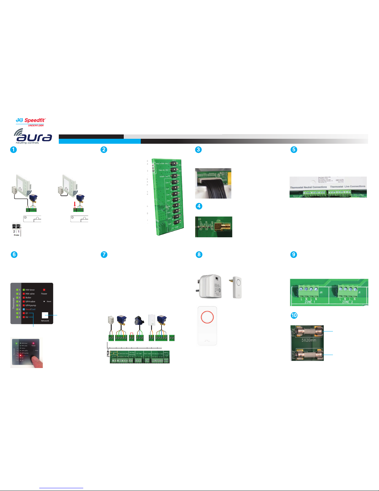
Motorised Valves, Pump, Boiler & Stat Connections
HW Cylinder Thermostat (Optional): If connecting the cylinder thermostat directly to the timer then
a link needs to be fitted between IN and OUT on the HW cylinder thermostat connection.
HW Motorised Valve (Optional): Used if timed hot water is required.
Overheat Thermostat (Optional): Used for connecting a pipe thermostat to prevent over
temperature water damaging sensitive floors. Remove the link and connect the pipe thermostat so it
is Normally Closed. The pipe stat will open if overheating occurs and the UFH pump will stop running.
Boiler Enable (Optional): This Volt Free connection must come from the boiler thermostat
connection. When any zone calls for heat the boiler enable will close causing the boiler to run. If work
is being carried out on the boiler then power to and from the switch will cease. (Do not connect to
the boiler IN terminal by linking a 230v feed from the wiring centre).
UFH Motorised Valve (Optional): If a UFH motorised valve is fitted then remove the link between
OR and GR.
Heat/Cool Changeover (Optional): This connection allows heat/cool changeover of all
thermostats using a single external switch (installer supplied).
Switch: Open-Heating, Closed-Cooling.
Thermostat Connections
Thermostat connections are to power the thermostats only. There is no switched live needed
as this is done with a wireless signal. Power can therefore be supplied to the thermostat
locally from any suitable power source if connecting to the wiring centre from the thermostat
is difficult. Battery powered wireless thermostats can also be used. These can be mixed with
230v Wireless Thermostats as an alternative.
Actuator Connections
Actuator connections corresponding to the thermostat connections. Up to 2 cables can be
used in each connection (4 actuators per Zone). If more than that number needs to be
connected, then an external junction box will be needed. A maximum of 6 actuators can be
connected to a zone in this manner.
Wireless - Information Display
After setting up, the Coordinator will assign the Wiring Centre a number. This is because more than
1 Wiring Centre may be used on a project. Pressing the network button will illuminate the relevant
number. The example shown is for Wiring Centre 1. If 1 & 2 are lit it would be Wiring Centre 2.
Dip Switch Set Up
In order for the wiring centre to be able to control UFH and
radiators, there is a need to turn off the UFH pump for a
zone when that zone is to be used for radiators.
Example: When fitting a zone for radiators or towel rail
then the Dip Switch that zone should be switched to OFF.
The Dip Switches for this are located under the front lid.
When the zone switch is in the ON position the UFH pump
will run when that zone is calling for heat along with the
boiler. When it is in the OFF position then the UFH pump
will not run but the boiler will fire.
Note: Zone valves controlled by the actuator connections
require only the live, neutral and earth wires to be
connected to the corresponding zone.
There are three other function switches as well.
Pump & Boiler delay: This gives a three minute delay to
allow actuators to open before the boiler fires.
Pump Only Delay:
Delays only the UFH pump from firing
for three minutes.
Actuator NO or NC: This refers to Normally Open or
Normally Closed. JG actuators supplied in NC configuration.
Ribbon Connection
This must be carefully removed or replaced when removing or replacing the wiring centre
cover, being careful to ensure the correct orientation.
Coordinator
A Coordinator is required by all wireless systems and must remain powered.
Fuses
Aerial Connection
Sensor Terminals
Can be used for external AIR floor sensor when configured as a thermostat.
Can also be used for cylinder thermostat when conected for hot water.
Thermostat Zones
Network Button
Groups 1 and 2
T1.6AH 250VP
T12AH 250VP
Hot Water Connections
Option 1 -
Connect cylinder thermostat
to Wiring Centre.
HW MOTORISED
VALVE
HW CYLINDER
STAT
IN OUT
BR EA N
SL N
230V AC
HW TIMER CONNECTION
L SLN
ZONE 1
L SL N
ZONE 2
L
OR GR
HW MOTORISED
VALVE
HW CYLINDER
STAT
IN OUT
BR EA N
SL N
230V AC
HW TIMER CONNECTION
L SLN
ZONE 1
L SL N
ZONE 2
L
OR GR
EARTH AS REQUIRED
230V 1.5MM2CABLE
(INSTALLER SUPPLIED)
230V 1.5MM
2
CABLE
(INSTALLER SUPPLIED)
HW MOTORISED
VALVE
HW CYLINDER
STAT
IN OUT
BR EA N
SL N
230V AC
HW TIMER CONNECTION
L SLN
ZONE 1
L SL N
ZONE 2
L
OR GR
EARTH AS REQUIRED
Optional
Hot Water
Motorised
Valve
Optional
Hot Water
Motorised
Valve
Option 2 - Connect cylinder thermostat directly to
Wireless Hot Water Timer for communication with the
Wiring Centre. A link will be needed between IN and OUT
on the Wiring Centre as shown by the arrow.
HW CYLINDER
THERMOSTAT
HW MOTORISED
VALVE
UFH MOTORISED
VALVE
OVERHEAT
STAT
IN OUT IN OUT IN OUTBR EA N NL EOR GR BR EA N OR GR
UFH PUMP BOILER
ENABLE
IN OUT
HEATING/
COOLING
EARTH AS REQUIRED
230V 1.5MM2CABLE
(INSTALLER
SUPPLIED)
SUPPLIED
CABLE
SUPPLIED
CABLE
230V 1.5MM
2
CABLE
(INSTALLER
SUPPLIED)
230V 1.5MM2CABLE
(INSTALLER
SUPPLIED)
JGWCW - Wireless 8 Zone Wiring Centre
Z2105/413/0817
speedfitUFH.co.uk
Technical Help Desk: 01895 425333
Wiring Diagram and Instruction Manual
 Loading...