

Page 1
TYPE 5620/5620P
DUAL O-RING CARTRIDGE SEAL
Installation, Operation & Maintenance Instructions
PAGE
1
Foreword
These instructions are provided to familiarize the user with the seal and its
designated use. The instructions must be read and applied whenever work
is done on the seal, and must be kept available for future reference.
Safety Instructions
1. The following designations are used in the installation instructions to
highlight instructions of particular importance.
NOTE: Refers to special information on how to install or operate
Refers to special information or instructions directed
ATTENTION
Refers to mandatory instructions designed to
!
2. Installation, removal and maintenance of the seal must be carried out
only by qualified personnel who have read and understood these
installation instructions.
3. The seal is designed exclusively for sealing rotating shafts. The
manufacturer cannot be held liable for use of the seal for purposes other
than this.
4. The seal must only be used in technically perfect condition, and must
be operated within the recommended performance limits in accordance
with its designated use set out in these installation instructions.
the seal most efficiently.
towards the prevention of damage to the seal or its
surroundings.
prevent personal injury or extensive damage to the
seal or its surroundings.
ATTENTION
If the seal is to be used for an application other than that originally intended
or outside the recommended performance limits, John Crane must be
contacted before its installation and use.
Any warranty may be affected by improper handling, installation, or use of
this seal. Contact John Crane for information as to exclusive product
warranty and limitations of liability.
If questions or problems arise, contact your local John Crane representative
or the original equipment manufacturer, as appropriate.
ATTENTION
5. If the pumped fluid is hazardous or toxic, appropriate precautions
must be taken to ensure that any seal leakage is adequately contained.
Further information on sealing hazardous or toxic fluids should be
obtained from John Crane prior to seal installation.
6. Fluorocarbon components should never be burned or incinerated as
the fumes and residues are highly toxic. If fluorocarbons are accidentally
heated above 400˚C/750˚F, they can decompose. Protective gloves
should be worn as hydrofluoric acid may be present.
7. PTFE components should never be burned or incinerated as the
fumes are highly toxic.
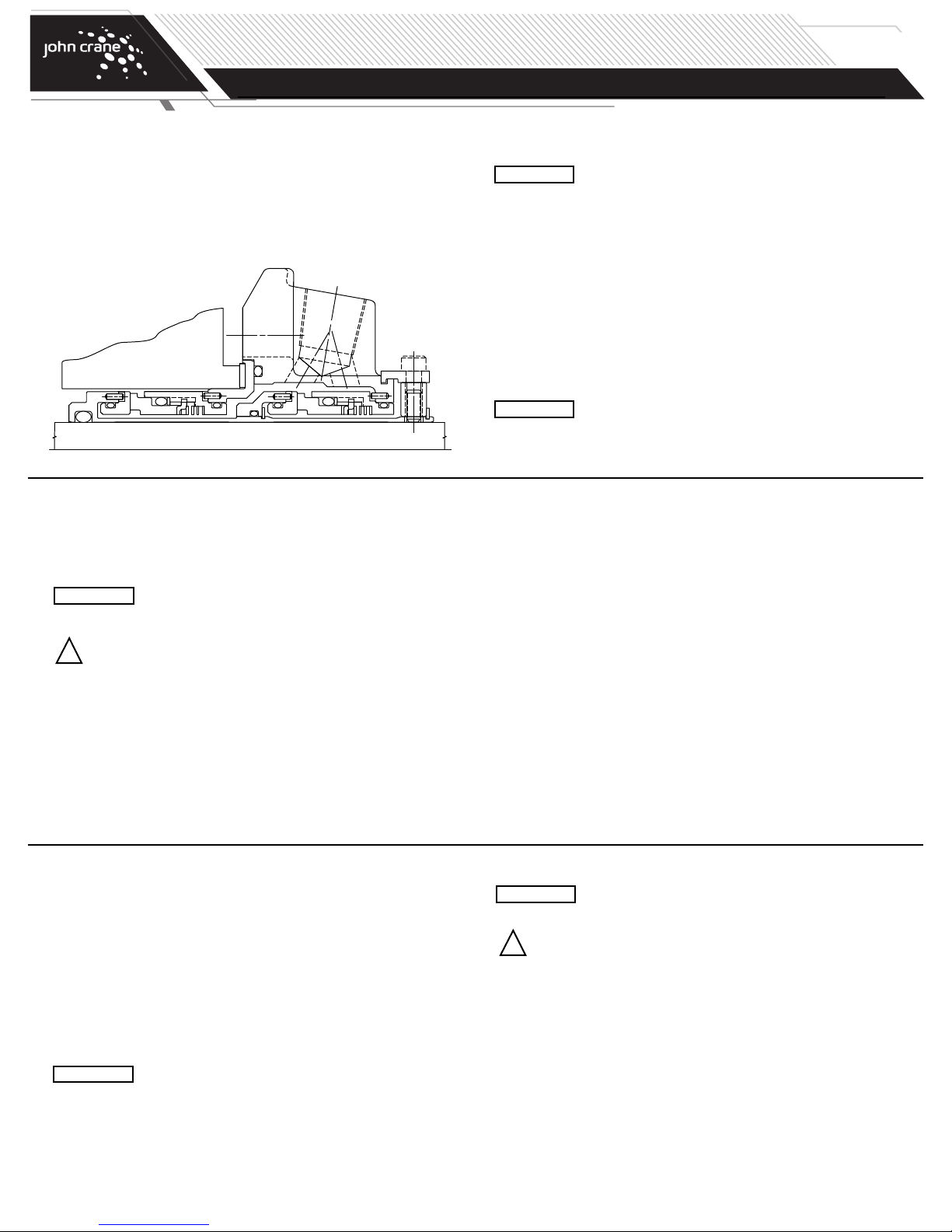
These instructions are for the installation and operation of a
seal as used in rotating equipment and will help to avoid
danger and increase reliability. The information required may
change with other types of equipment or installation
arrangements. These instructions must be read in conjunction
with the instruction manuals for both the pump and any
ancillary equipment.
John Crane mechanical seals are precision products and must
be handled appropriately. Take particular care to avoid damage
to lapped sealing faces and to flexible sealing rings. Do not
excessively compress the seal before or during installation.
Before Starting the Equipment
1. Check the pump at the coupling for proper alignment of the driver
or motor.
2. Ensure that the gland plate nuts/bolts are securely tightened according
to the pump manual instructions, and that all screws are securely
fastened.
3. Complete the assembly of the pump, and turn the shaft (by hand if
possible) to ensure free rotation.
4. Consult all available equipment operating instructions to check for
correctness of all piping and connections, particularly regarding seal
recirculation/flush, heating or cooling requirements, and services
external to the seal.
This mechanical seal is designed to operate in a liquid so
ATTENTION
5. Check that the seal chamber fluid lines are open and free of any
obstruction, and ensure that the seal chamber is properly vented
and filled with liquid - refer to the pump instruction manual.
the heat energy it creates is adequately removed.
Therefore, the following check should be carried out not
only after seal installation, but also after any period of
equipment inactivity.
ATTENTION
!
WARNING: Seal installation should be handled only by qualified
Dry-running - often indicated by a squealing noise from
the seal area - will cause overheating and scoring or other
damage to the sealing surfaces, resulting in excessive
leakage or a much shortened seal life.
Before start-up, ensure that all personnel and
assembly equipment have been moved to a safe
distance so there is no contact with rotating parts
on the pump, seal, coupling, or motor.
personnel. If questions arise, contact the local
John Crane representative. Improper use and/or
installation of this product could result in injury to the
person and/or harmful emissions to the environment,
and may affect any warranty on the product. Please
contact the company for information as to exclusive
product warranty and limitations of liability.
Page 2
6
5
19
13 17 412022 21 312 815
14
16
18
11
9
10
7
2
TURN SHAFT BY HAND AND NOTE
M
EASUREMENT ON DIAL INDICATOR
MOUNT
DIAL INDICATOR
O
N SHAFT
TURN SHAFT BY HAND AND NOTE
MEASUREMENT ON DIAL INDICATOR
MOUNT
DIAL INDICATOR
ON SEAL CHAMBER
F
ACE
6
3
SHAFT OR SLEEVE
B
ORE
O
D +.000" -.002"
.040 LG. X 20˚ CHAM.
63
MOVE SHAFT IN AXIAL DIRECTION
BY HAND. NOTE MEASUREMENT
ON DIAL INDICATOR
MOUNT
DIAL INDICATOR
ON SHAFT
.040"
20˚
TYPE 5620/5620P
DUAL O-RING CARTRIDGE SEAL
Installation, Operation & Maintenance Instructions
PAGE
2
G
eneral Instructions
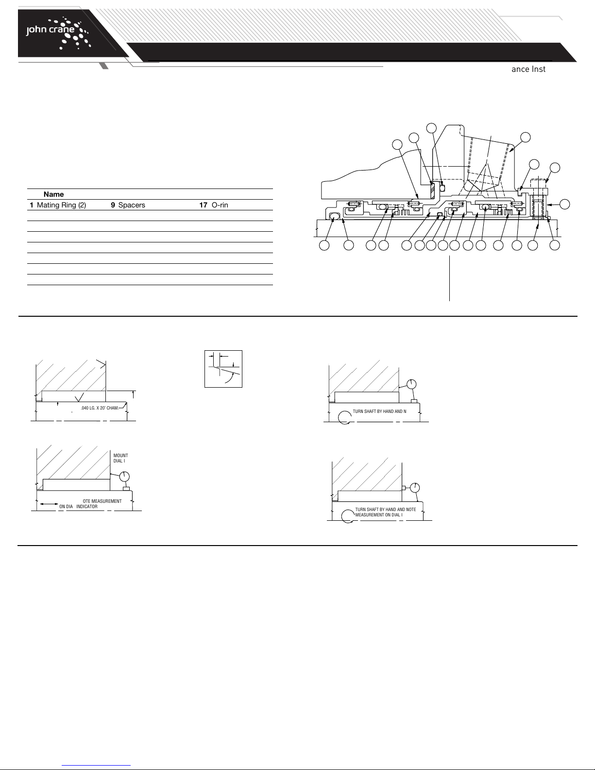
1. Study the engineering layout drawing to confirm the proper seal
arrangement for the pump being used. Type 5620 seals are
designed for versatility and can be assembled in various ways.
The following instructions describe the standard configurations.
2. To assure satisfactory operation, handle seal with care. Take
particular caution to see that the lapped sealing faces are not scratched
or damaged.
art Name
P
1 Mating Ring (2) 9 Spacers 17 O-ring
2 O-ring (2) 10 Cap Screws 18 O-ring
3 Primary Ring (2) 11 Gland Plate Assembly 19 Snap Ring
4 O-ring (2) 12 Spring (2) 20 Snap Ring
5 Sleeve Assembly 13 Sleeve Adapter* 21 Drive Ring (2)
6 O-ring 14 Gasket 22 Anti X-Ring (2)
7 Collar 15 O-ring (2)
8 Set Screws 16 Gland Adapter
Or Pumping Ring for 5620P.
*
Preparing the Equipment
1. Check seal chamber dimensions and finishes.
Typical Type 5620 or 5620P Dual Cartridge
Seal Arrangement
Inboard
Side
3. Determine squareness of seal chamber face to shaft:
Rotating Mating Ring
Sizes to 3.000"= 0.005" FIM max.
3.000" and greater = 0.007" FIM max.
Rotating Seal Head
Sizes to 3.000"= 0.002" FIM max.
3.000" and greater = 0.003" FIM max.
Outboard
Side
2. Measure axial end play: Sizes to 3.000"= 0.003" FIM max.
3.000" and greater = 0.005" FIM max.
4. Measure shaft runout: Sizes to 3.000"= 0.002" FIM max.
3.000" and greater = 0.003" FIM max.
NOTE: If measured dimensions exceed those values given, correct the equipment to meet specifications prior to seal installation.
Type 5620 Dual O-ring Cartridge Seal Assembly
Assemble the Type 5620 as follows, referring to the applicable engineering
layout drawing.
NOTE: These instructions apply to a rotating mating ring configuration
NOTE: Elastomeric O-rings can be damaged or destroyed if care is
1. Place gland plate on table with O-ring groove side facing up.
2. Install lubricated O-ring into outside diameter (OD) groove of inboard
mating ring.
3. Stand sleeve on its base and slide mating ring over sleeve, align pins
and press in place.
4. Install set screws in collar.
inboard and a rotating mating ring outboard. The inboard seal
assembly and mating ring positions could be reversed should
an application require.
not taken. Prior to assembly of O-ring into groove, make sure
groove is clean and free of foreign materials. Lubricate both
groove and O-ring prior to installation with light lube oil (SAE
#10 or #20) or silicone grease (such as Dow Corning
compound #4.) For ethylene propylene elastomers, do not
lubricate with petroleum products.
5. Loosely attach the spacers to the collar with cap screws.
6. Set the gland plate assembly O-ring groove side down on table. Install
collar on gland plate assembly and engage spacers into groove, aligning
spacers with pipe taps of gland plate. Uniformly finger tighten the cap
screws.
7. Install lubricated O-ring into outside diameter (OD) groove of inboard
retainer.
8. Place spring inside retainer.
9. Insert drive ring in retainer with tabs facing opposite of spring. Align
notches with dents in retainer.
10. Insert anti X-Ring in retainer.
11. Install lubricated O-ring on the primary ring. Push down until seated on
the step of the outside diameter (OD) of primary ring.
12. Align notches on primary ring tail with drive ring tabs and press into bore
of retainer. Make sure primary ring is engaged into tabs and moves freely.
13. Insert seal assembly in gland plate adapter, align pins and press in place.
14. Clean faces of primary and mating rings with denatured alcohol and a
lint-free cloth.
Page 3
L39L91 MIN. BOX DEPTH
L92
L90 MIN. NEAREST OBSTRUCTION
D3
L56
D26
D4
D1 +.000"
-.002"
D30
*
MIN.
TURN
DIAM.
L12
L23
SLOT
WIDTH
M
N
TYPE 5620/5620P
DUAL O-RING CARTRIDGE SEAL
Type 5620 Dual O-Ring Cartridge Seal Assembly (cont.)
PAGE
3
Installation, Operation & Maintenance Instructions
15. Stand sleeve on its base and slide seal assembly over sleeve until seal
faces touch.
16. Install lubricated O-ring into ID groove of sleeve adapter or pumping ring.
17. Slide sleeve adapter over sleeve, aligning pins of adapter with pins of
sleeve. Push down to engage “drive flats” until adapter stops at step
of sleeve.
18. Carefully slide snap ring over the end of sleeve. Using assembly tool,
push the snap ring in place inside the sleeve adapter until it snaps in
place. Be careful not to scratch the sleeve adapter.
19. Install lubricated O-ring into OD groove of outboard mating ring.
20. Slide mating ring over sleeve, align pins and press in place.
21. Install lubricated O-ring into OD groove of outboard retainer.
22. Place spring inside retainer.
23. Insert drive ring in retainer with tabs facing opposite of spring. Align
notches with dents in retainer.
24. Insert anti X-ring in retainer.
25. Install lubricated O-ring on the primary ring. Push down until seated on
the step of the OD of primary ring.
26. Align notches on primary ring tail with drive ring tabs and press into bore
of retainer. Make sure primary ring is engaged into tabs and moves freely.
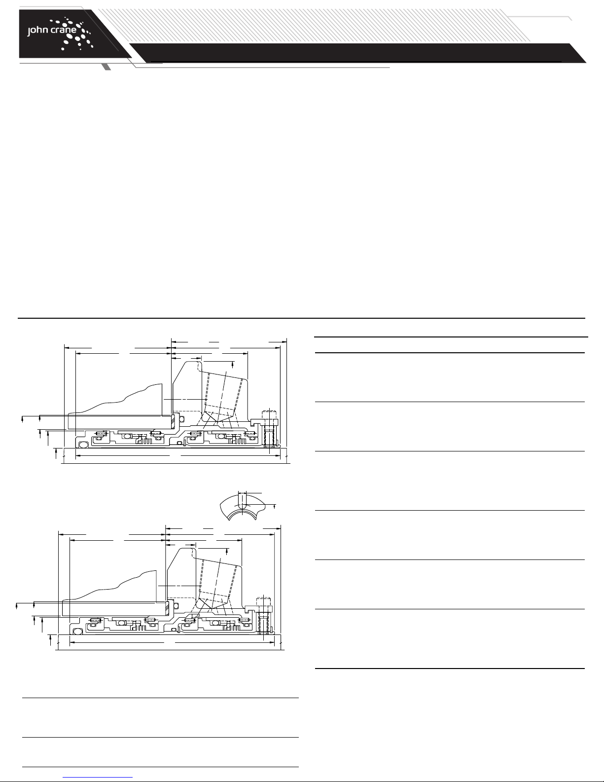
Type 5620 Installation Dimensions
*Oversize bore seals only
Type 5620P Installation Dimensions
L90 MIN. NEAREST OBSTRUCTION
L92
D30
*MIN.
TURN
DIAM.
D4
D3
D1 +.000"
-.002"
Type 5620/5620P Oversize Bore Dual Cartridge
L56
L12
Dimensional Data (inches)
Seal D4 Min.
Size/D1 D3 Min. Max. D26 L12 L23 L39 L56 L90 L91 L92 M N Turn Diam.
1.375 1.939 2.875 3.023 5.375 3.851 1.446 2.062 0.625 2.125 1.914 1.789 0.562 4.062 3.268
1.750 2.406 3.500 3.925 6.500 3.995 1.487 2.125 0.656 2.187 1.995 1.870 0.687 5.093 3.885
1.875 2.549 3.625 3.734 6.500 3.995 1.487 2.125 0.656 2.187 1.995 1.870 0.687 5.093 4.006
2.125 2.798 3.875 4.250 7.250 4.355 1.570 2.282 0.749 2.407 2.198 2.073 0.687 5.687 4.264
2.500 3.301 4.750 5.078 8.000 4.545 1.788 2.563 0.749 2.625 2.107 1.982 0.687 6.062 5.000
2.625 3.551 4.625 4.740 8.000 4.594 1.788 2.500 0.749 2.562 2.219 2.094 0.687 6.062 5.000
2.750 3.551 4.750 4.875 8.000 4.594 1.697 2.407 0.656 2.532 2.312 2.187 0.687 6.062 5.139
L39L91 MIN. BOX DEPTH
L23
D26
*Oversize bore seals only
27. Place gland plate onto table with O-ring side up.
28. Insert seal assembly in gland plate, align pins and press in place. Turn
gland plate over and confirm that retainer is flush with end of gland plate.
29. Clean faces of primary and mating rings with denatured alcohol and a
lint-free cloth.
30. Insert O-ring in face groove of gland plate.
31. Making sure seal face does not fall out, slide gland plate over sleeve
until seal faces touch.
32. Carefully rotate gland plate until holes in sleeve are lined up with the
collar set screws.
33. Carefully press down on gland plate and install snap ring over the end
of sleeve. Do not over compress gland plate or this may damage
the seal.
34. Tighten set screws until they start to enter the sleeve ID.
35. Uniformly tighten cap screws on spacers.
36. Install gasket and sleeve O-ring.
37. Pressure test according to John Crane standard QA-5-0569.
38. Plug gland pipe taps as noted with metal plugs provided.
Type 5620/5620P Dual Cartridge Dimensional Data (inches)
Seal D4
Size/D1 D3 Min. Max. D26 L12 L23 L39 L56 L90 L91 L92 M N
1.000 1.564 1.625 1.889 4.000 3.705 1.353 1.954 0.531 2.000 1.876 1.751 0.525 2.805
1.125 1.689 1.750 2.015 4.125 3.851 1.446 2.062 0.531 2.125 1.914 1.789 0.525 2.933
1
.250 1.812 1.875 2.294 4.250 3.851 1.446 2.062 0.531 2.125 1.914 1.789 0.525 3.213
1.375 1.939 2.000 2.421 4.375 3.851 1.446 2.062 0.531 2.125 1.914 1.789 0.525 3.338
1.500 2.187 2.250 2.680 4.875 3.995 1.487 2.125 0.593 2.187 1.995 1.870 0.525 3.599
1.625 2.312 2.375 2.812 5.000 3.995 1.487 2.125 0.593 2.187 1.995 1.870 0.562 3.766
1.750 2.406 2.480 2.918 5.250 3.995 1.487 2.125 0.593 2.187 1.995 1.870 0.563 3.875
1.875 2.549 2.625 2.918 5.250 3.995 1.487 2.125 0.593 2.187 1.995 1.870 0.563 3.875
2.000 2.673 2.750 3.015 5.500 4.355 1.601 2.312 1.063 2.375 2.167 2.042 0.562 4.000
2.125 2.798 2.875 3.360 5.859 4.355 1.601 2.313 0.593 2.375 2.167 2.042 0.687 4.469
2.250 2.923 3.000 3.485 6.500 4.355 1.601 2.312 0.593 2.375 2.167 2.042 0.687 4.566
2.375 3.048 3.125 3.610 6.500 4.545 1.717 2.466 0.625 2.825 2.204 2.079 0.687 4.719
2.500 3.301 3.375 3.891 6.750 4.545 1.717 2.563 0.625 2.625 2.107 1.982 0.687 5.000
2.625 3.551 3.625 4.062 6.750 4.594 1.625 2.500 0.625 2.562 2.219 2.094 0.687 5.170
2.750 3.551 3.625 4.062 6.750 4.594 1.625 2.500 0.625 2.562 2.219 2.094 0.687 5.170
2.875 3.614 3.750 4.186 7.000 4.594 1.725 2.500 0.625 2.562 2.219 2.094 0.687 5.312
3.000 3.864 4.000 4.469 7.750 4.594 1.787 2.562 0.685 2.625 2.157 2.032 0.812 5.720
3.125 4.022 4.125 4.600 7.875 4.687 1.593 2.562 N/A 2.687 2.250 2.125 0.812 5.845
3.250 4.022 4.134 4.600 7.437 4.687 1.593 2.510 N/A 2.635 2.302 2.177 0.812 5.845
3.375 4.246 4.375 4.850 8.125 4.687 1.593 2.562 N/A 2.687 2.250 2.125 0.812 6.095
3.500 4.371 4.500 4.975 8.250 4.687 1.593 2.562 N/A 2.687 2.250 2.125 0.812 6.220
3.625 4.500 4.625 5.100 8.375 4.687 1.593 2.562 N/A 2.687 2.250 2.125 0.687 6.250
3.750 4.625 4.724 5.199 8.750 4.687 1.593 2.562 N/A 2.687 2.250 2.125 0.687 6.770
3.875 4.750 4.875 5.375 8.750 4.687 1.593 2.562 N/A 2.687 2.250 2.125 0.812 6.636
4.000 4.875 5.000 5.500 9.000 4.687 1.593 2.562 N/A 2.687 2.250 2.125 0.812 6.761
4.125 5.000 5.125 5.625 9.000 4.687 1.593 2.562 N/A 2.687 2.250 2.125 0.812 6.886
4.250 5.125 5.250 5.750 9.250 4.687 1.593 2.562 N/A 2.687 2.250 2.125 0.812 7.011
4.500 5.375 5.500 6.000 9.500 4.687 1.593 2.562 N/A 2.687 2.250 2.125 0.812 7.261
4.750 5.625 5.750 6.313 10.375 4.687 1.593 2.562 N/A 2.687 2.250 2.125 0.812 7.574
5.000 6.125 6.760 7.260 12.000 5.515 1.749 3.043 N/A 3.168 2.598 2.473 0.812 10.000
5.250 6.375 7.010 7.510 12.250 5.515 1.749 3.043 N/A 3.168 2.598 2.473 0.812 10.250
5.500 6.625 7.500 8.000 12.687 5.515 1.749 3.043 N/A 3.168 2.598 2.473 0.937 10.500
Page 4
TYPE 5620/5620P
DUAL O-RING CARTRIDGE SEAL
Installing the Seal
1. Before starting the installation, read the following instructions carefully.
2. Remove the seal from its packaging, inspect for any damage, and wipe
clean.
3. The equipment should be clean and meet the specifications noted in the
“Preparing the Equipment” section. Lubricate sleeve O-ring with lubricant recommended in chart below. Lubricate shaft sparingly. Lubricate
gland plate bolts/nuts as required.
ELASTOMER LUBRICANT
Fluoroelastomer Vegetable Oil, Animal Oil, Mineral-Hydrocarbon Oils,
(i.e. Viton™) Soap Solution, Parker ‘Super-O-Lube’, Silicone Grease
Ethylene Propylene Vegetable Oil, Polywater™, Soap Solution, Glycerine,
Propylene Glycol, Silicone Grease
Perfluoroelastomer Vegetable Oil, Animal Oil, Mineral-Hydrocarbon Oils
(i.e. Kalrez™)
OTE: Always use a lubricant that is compatible with your machinery and product.
N
Use lubricant sparingly, only enough to install seal with ease.
Viton and Kalrez are registered trademarks of DuPont.
olywater is a registered trademark of American Polyware Co.
P
PAGE
4
Installation, Operation & Maintenance Instructions
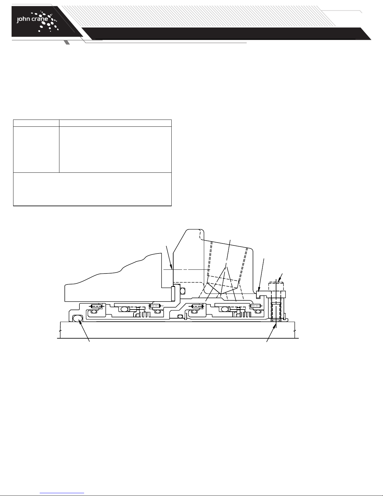
4. Make sure that gland adapter gasket is properly positioned, and
that collar set screws do not extend past sleeve ID. Slide complete
cartridge seal assembly onto shaft. For ANSI pumps position gland
plate so pipe connection #1 is at or near top dead center. For DIN
pumps, position gland plate so slot between pipe connections
#3 and #4 is at or near top dead center. Slide cartridge onto studs
(if applicable) until gasket is flush against the face of seal chamber.
Hand tighten gland plate bolts/nuts.
5. Reassemble pump and make all necessary impeller adjustments.
6. Continue tightening gland plate bolts/nuts in an alternating pattern
until gland plate is secure (1/4 turns, 180˚ apart). Do not overstress or distort gland plate.
7. Tighten collar set screws evenly (1/4 turns, 180˚ apart), securing
cartridge seal to shaft.
8. Remove spacers and save.
9. Make appropriate piping connections to seal assembly.
O-RING
GLAND BOLTS
SPACERS
CAP SCREWS
SET SCREWS
Page 5
PAGE
TYPE 5620/5620P
5
DUAL O-RING CARTRIDGE SEAL
Installation, Operation & Maintenance Instructions
Installing the Seal (continued)
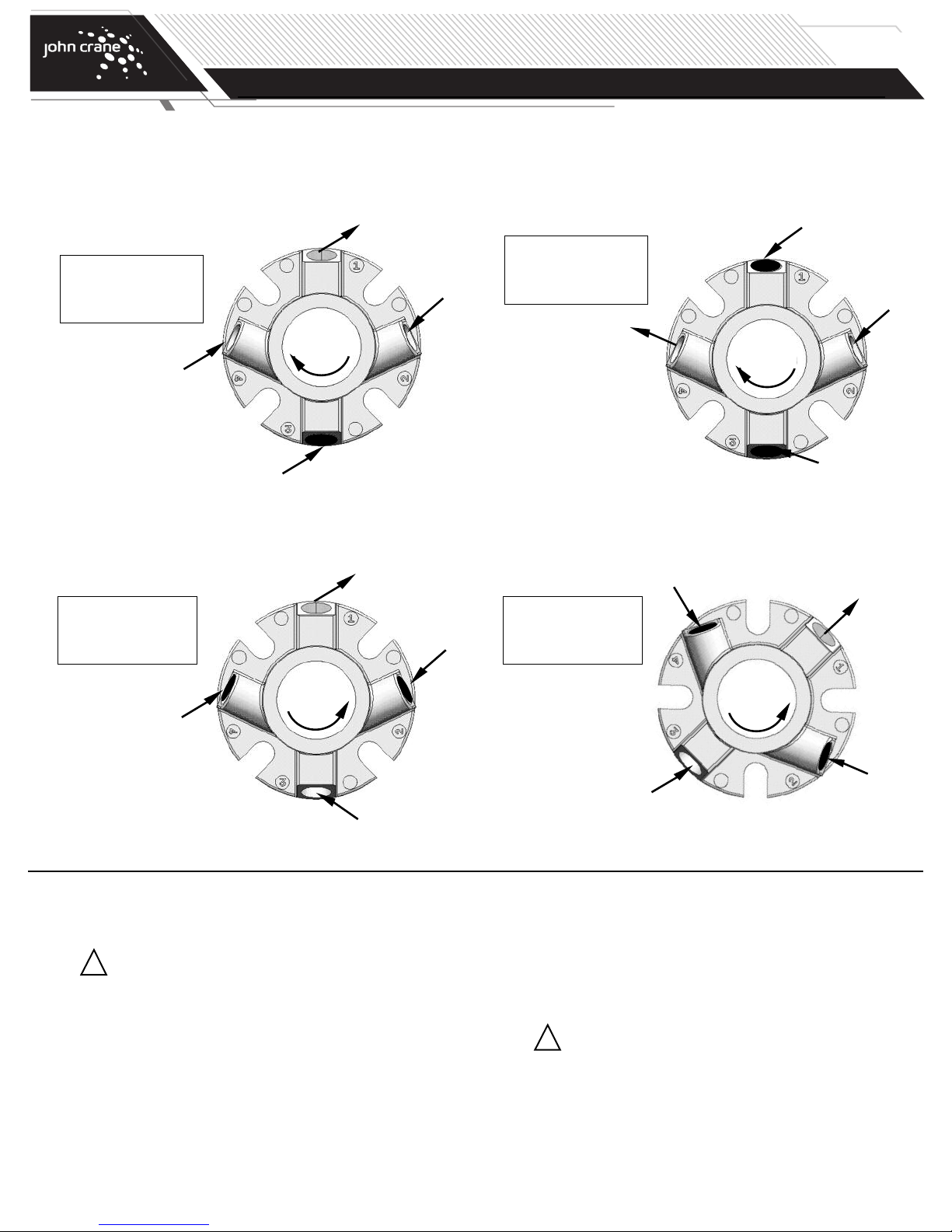
The piping should follow the guidelines established in the John Crane Manual LE-Plan 52/53-A. It is also recommended that a Plan 11 (by-pass from
discharge) be used with the standard plan 52/53. For DIN pumps rotate gland 135˚ CCW. Use port #3 as inlet and #4 as outlet. Plug 1 and 2.
Preferred
Port #1 - Outlet/Vent
Port #2 - Inlet
Port #3 - Plugged
Port #4 - Plugged
Clockwise
Rotation
Plugged
Direction of view is from
the driver end of pump.
Drain (Plugged)
For Counter Clockwise Shaft Rotation:
The piping should follow the guidelines established in John Crane Manual LE-Plan 52/53-A. It is also recommended that a Plan 11 (by-pass from discharge)
be used with the plan 52/53. For DIN style bolting pattern, rotate gland 45˚ clockwise.
Port #1 - Outlet
Port #2 - Plugged
Port #3 - Inlet
Port #4 - Plugged
Counter
Clockwise
Rotation
Plugged
Outlet “O”
Inlet “I”
Outlet
Plugged
Option #1
Port #1 - Vent
Port #2 - Inlet
Port #3 - Plugged
Port #4 - Outlet
Outlet “O”
Option #1 requires
manual venting of
entrapped air through
port #1 prior to start-up.
45º Clockwise
Port #1 - Outlet
Port #2 - Plugged
Port #3 - Inlet
Port #4 - Plugged
Vent (Plugged)
Inlet “I”
Clockwise
Rotation
Drain (Plugged)
Plugged
Outlet
Counter
Clockwise
Rotation
Inlet
Decommissioning the Equipment
1. Ensure that the pump is electrically isolated.
If the equipment has been used on toxic or hazardous
2. Ensure that the pump is isolated by the appropriate valves.
fluids, ensure that the equipment is correctly
!
decontaminated and made safe prior to commencing
work. Remember fluid is often trapped during draining
and may exist outside the seal. The pump instruction
manual should be consulted to check for any special
precautions.
Check that the fluid is drained and pressure is fully released.
Plugged
Inlet
Maintenance
No maintenance of a seal is possible while installed. Therefore, it is
recommended that a spare seal unit be held in stock to allow
immediate replacement of a removed seal.
It is recommended that used seals are returned to a John Crane service
location, as rebuilding to as-new specifications must be
carried out by qualified personnel.
It is the responsibility of the equipment user to ensure that
any parts being sent to a third party have appropriate safe
!
handling instructions externally attached to the package.
Quality Assurance
This seal has been assembled in accordance with John Crane quality
assurance standards and with proper maintenance and use will give safe
and reliable operation to the maximum recommended performance as
shown in any relevant approved John Crane publication.
Page 6

TYPE 5620/5620P
DUAL O-RING CARTRIDGE SEAL
Installation, Operation & Maintenance Instructions
PAGE
6
Ordering Information
1. Cartridge seal size = solid shaft or sleeve outside diameter (OD).
2. Select dual (5620 or 5620P) arrangement.
3. Determine whether standard or enlarged seal chamber configuration
is required.
4. Choose seal drawing number from chart below.
5. For other material combinations or size considerations, consult the local
John Crane representative..
Type 5620/5620P Cartridge Drawing Numbers
Standard Bore Layouts
Seal Size 5620 5620P
1.000 H-SP-39544 H-SP-39546
1.125 H-SP-37321 H-SP-37329
1.250 H-SP-39555 H-SP-39557
1.375 H-SP-37322 H-SP-37330
1.500 H-SP-39565 H-SP-39567
1.625 H-SP-39575 H-SP-39577
1.750 H-SP-37323 H-SP-37331
1.875 H-SP-37324 H-SP-37332
2.000 H-SP-39585 H-SP-39587
2.125 H-SP-37325 H-SP-37333
2.250 H-SP-39595 H-SP-39597
2.375 H-SP-39605 H-SP-39607
2.500 H-SP-37326 H-SP-37334
2.625 H-SP-37327 H-SP-37335
2.750 H-SP-37328 H-SP-37336
2.875 H-SP-39615 H-SP-39617
3.000 H-SP-39625 H-SP-39627
3.125 H-SP-41627
3.250 H-SP-41632
3.375 H-SP-41638
3.500 H-SP-41643
3.625 H-SP-41648
3.750 H-SP-41653
3.875 H-SP-41956
4.000 H-SP-41658
4.125 H-SP-41663
4.250 H-SP-41667
4.500 H-SP-41670
4.750 H-SP-41673
5.000 H-SP-41676
5.250 H-SP-41679
5.500 H-SP-41682
*Type 5620 is not available in sizes over 3.000".
A pumping ring is required for 3.125" and above, use 5620P.
*
Materials of Construction - Standard
Primary Ring Carbon Graphite
Silicon Carbide (optional)
Mating Ring Silicon Carbide
Tungsten Carbide (Nickel Binder) (optional)
Cartridge Hardware 316 Stainless Steel*
Secondary Seal Fluoroelastomer*
Operating Limits
Pressure: Sizes up to 3.000" - 21 barg/300 psig max.
Sizes over 3.000" - 13 barg/200 psig max.
Temperature: -29˚C to 204˚C
Speed: To 25 mps/5000 fpm
*Various Options
/-20˚F to 400˚F
Type 5620/5620P Cartridge Drawing Numbers
Oversized Bore Layouts
Seal Size 5620 5620P
1.375 H-SP-38059 H-SP-38060
1.750 H-SP-38069 H-SP-38070
1.875 H-SP-38079 H-SP-38080
2.125 H-SP-39036 H-SP-39037
2.500 H-SP-39009 H-SP-39010
2.625 H-SP-38089 H-SP-38090
2.750 H-SP-39019 H-SP-39020
Page 7

TYPE 5620/5620P
DUAL O-RING CARTRIDGE SEAL
Installation, Operation & Maintenance Instructions
PAGE
7
Page 8
TYPE 5620/5620P
DUAL O-RING CARTRIDGE SEAL
Installation, Operation & Maintenance Instructions
PAGE
8
North America
United States of America
Tel: 1-847-967-2400
Fax: 1-847-967-3915
If the products featured will be used in a potentially dangerous and/or hazardous process, your John Crane representative should be consulted prior to
their selection and use. In the interest of continuous development, John Crane Companies reserve the right to alter designs and specifications without
prior notice. It is dangerous to smoke while handling products made from PTFE. Old and new PTFE products must not be incinerated. ISO 9001 and
ISO14001 Certified, details available on request.
©2015 John Crane
Europe
United Kingdom
Tel: 44-1753-224000
Fax: 44-1753-224224
Revised 10/15 www.johncrane.com IOM-5620/5620P
Latin America
Brazil
Tel: 55-11-3371-2500
Fax: 55-11-3371-2599
Middle East & Africa
United Arab Emirates
Tel: 971-481-27800
Fax: 971-488-62830
Asia Pacific
Singapore
Tel: 65-6518-1800
Fax: 65-6518-1803
 Loading...