

FOR:
PASSENGER CAR & LIGHT TRUCK WHEELS
VPI SYSTEM I
COMPUTER WHEEL BALANCER
OPERATION INSTRUCTIONS
Form 5787-1
Rev 04/19/2001


SAFETY INFORMATION
For your safety, read this manual thoroughly
before operating the JBC VPI System I Wheel Balancer
The JBC VPI System I Wheel Balancer is intended for use by properly trained automotive technicians. The safety messages presented in this section and throughout the
manual are reminders to the operator to exercise extreme caution when servicing tires
with these products.
There are many variations in procedures, techniques, tools, and parts for balancing
tires, as well as the skill of the individual doing the work. Because of the vast number
of wheel and tire applications and potential uses of the product, the manufacturer cannot possibly anticipate or provide advice or safety messages to cover every situation.
It is the automotive technician's responsibility to be knowledgeable of the wheels and
tires being serviced. It is essential to use proper service methods in an appropriate and
acceptable manner that does not endanger your safety, the safety of others in the work
area or the equipment or vehicle being serviced.
It is assumed that, prior to using the Model VPI System I Wheel Balancer, the
has a thorough understanding of the wheels and tires being serviced. In addition, it is
assumed he has a thorough knowledge of the operation and safety features of the
rack, lift, or floor jack being utilized, and has the proper hand and power tools necessary to service the vehicle in a safe manner.
Before using the Model VPI System I Wheel Balancer, always refer to and follow the
safety messages and service procedures provided by the manufacturers of the equipment being used and the vehicle being serviced.
IMPORTANT !! SAVE THESE INSTRUCTIONS -- DO NOT DISCARD !!
operator

IMPORTANT SAFETY INSTRUCTIONS
When using this equipment, basic safety precautions should always be followed,
including the following:
1. Read all instructions.
2. Do not operate equipment with a damaged power cord or if the equipment has been
damaged - until it has been examined by a qualified authorized service technician.
3. If an extension cord is used, a cord with a current rating equal to or more than that
of the machine should be used. Cords rated for less current than the equipment
may overheat. Care should be taken to arrange the cord so that it will not be tripped
over or pulled.
4. Always unplug equipment from electrical outlet when not in use. Never use the
cord to pull the plug from the outlet. Grasp plug and pull to disconnect.
5. To reduce the risk of fire, do not operate equipment in the vicinity of open
containers of flammable liquids (gasoline).
6. Keep hair, loose fitting clothing, fingers and all parts of the body away from moving
parts.
7. Adequate ventilation should be provided when working on operating internal
combustion engines.
8. To reduce the risk of electric shock, do not use on wet surfaces or expose to rain.
9. Do not hammer on or hit any part of the control panel with weight pliers.
10. Do not allow unauthorized personnel to operate the equipment.
11. Do not disable the hood safety interlock system or bypass the intended operation.
12. Use only as described in this manual. Use only manufacturer’s recommended
attachments.
13. Always securely tighten the wing nut before spinning the shaft.
14. ALWAYS WEAR SAFETY GLASSES. Everyday eyeglasses only have impact
resistant lenses, they are NOT safety glasses.
15. Balancer is for indoor use only.
SAVE THESE INSTRUCTIONS
Page 2

John Bean VPI System I Operators Manual
TABLE OF CONTENTS
General Safety Instructions Pages 1 & 2
1.0 Introduction Page 4
1.1 Safety Notice Page 4
1.2 Balancer Application Page 4
1.3 Specifications Page 5
1.4 Balancer Features Page 5
1.5 Standard Accessories Page 6
1.6 Optional Accessories Page 6
1.7 Dimensions Of The Machine Page 7
1.8 Installation Area Page 7
1.9 Installation Instructions Page 7
2.0 Shaft Adapter Installation Page 7
2.1 Wheel Guard Installation Page 8
2.2 Electrical Installation Page 8
2.3 Perform a User Calibration Page 8
3.0 Terminology Page 9
4.0 Balancer Operation Page 10
4.1 Inspection Check list Page 10
4.2 Wheel Mounting Page 10
4.2.1 Mounting of Standard Wheels Page 10
4.2.2 Mounting of Light Truck Wheels Page 11
4.3 Mode Selection Page 11
4.3.1 Weight Placement Modes Page 11
4.4 Selecting Operator Preferences Page 12
4.4.1 Fine Balance Mode Page 12
4.4.2 Ounce /Grams Conversion Page 12
4.4.3 Inch/Millimeter Conversion Page 12
4.4.4 Selection of Operator A/B Page 12
4.5 Entering Rim Parameters Page 13
4.5.1 Entering Distance (offset) with SAPE Page 13
4.5.2 Entering Rim Diameter Page 13
4.5.3 Entering Rim Width Page 13
4.5.3.1 Manual Distance Entry Page 13
4.6 Correcting the Imbalance Page 14
4.7 Verifying Results Page 14
4.8 Vibration Problems Page 14
5.0 Matching Program Page 15
6.0 Optimization Program Page 17
7.0 Alu-S Program Page 18
8.0 Spoke Mode Page 19
9.0 Split Weight Mode Page 20
10.0 User Shaft Calibration Page 21
11.0 Distance Gauge Calibration Page 22
11.0 Explanation of "F" Codes Page 23
12.0 Maintenance Page 23
13.0 Trouble Shooting Page 23
Page 3

1.0 INTRODUCTION
Congratulations on purchasing the VPI System I computer wheel balancer. This wheel balancer is
designed for ease of operation, accuracy, reliability and speed. With a minimum of maintenance and
care your wheel balancer will provide many years of trouble-free operation.
Instructions on use, maintenance and operational requirements of the machine are covered in this
manual.
STORE THIS MANUAL IN A SAFE PLACE FOR FUTURE REFERENCE.
READ THIS MANUAL THOROUGHLY BEFORE USING THE MACHINE.
1.1 SAFETY NOTICE
This manual is a part of the balancer product.
Read carefully all warnings and instructions of this manual since they provide important information
concerning safety and maintenance.
1.2 BALANCER APPLICATION
The John Bean wheel balancer model VPI System I is intended to be used as a device to balance car,
and light truck wheels within the following range:
Maximum wheel diameter : 44” (1117mm)
Maximum wheel width : 16” (530mm)
Maximum wheel weight : 120lbs (54 kg)
This device is to be only used in the application for which it is specifically designed.
Any other use shall be considered as improper and thus not reasonable.
The manufacturer shall not be considered liable for possible damages caused by improper, wrong or
non reasonable use.
Page 4

John Bean VPI System I Operators Manual
1.3 VPI System I SPECIFICATIONS
Computerized digital wheel balancer for car, light truck
wheels.
Weight Imbalance Accuracy .1 oz / 2 grams
Weight Placement Resolution ± .7 degrees
Weight Imbalance Resolution:
Roundoff Mode .25 oz / 5 grams
Non-Roundoff Mode .05 oz / 1 gram
Max. Shaft Weight Capacity 120 lbs / 54 kg
Max.Tire Diameter 44" / 1117 mm
Rim Width Capacity 1.5"-15" / 76 mm - 406 mm
Max. Tire Width 19” / 482 mm
Rim Diameter Capacity 8"-20" / 152 mm-660 mm
Balancing Cycle Time. 7 seconds or less
Shaft Speed at calculation >100 RPM
Electrical 115vac, 1ph, 50-60Hz, 8A
Required Work Area 54” x 52” (1372 x 1321 mm)
Shipping Weight, complete 325 lbs/147kg
Shipping Dimensions 52.75”h 41.5”w 37”d
Machine Dimensions 54”h 45”w 48.5”d
Actual Weight with Accessories 309 lbs / 140 kg
Operating Temperature Range 32-122F / 0-50C
1.4 FEATURES
ACCURACY
• Weight placement accuracy to as low as ± .7°
• Weight imbalance accuracy to 2 grams.
• Self test check with every power up cycle.
• Fast operator calibration.
• Pre-programmed Error Codes indicate procedural
errors or safety concerns.
SPEED and DURABILITY
• Automatic distance entry. Simply touch the distance
arm to the wheel, the distance parameter is automatically entered.
• Quick clamp speed nut reduces wheel mounting time.
• Captured back spring eliminates having to handle the
backing spring.
• Quick cycle time.
• Automatic recalculation if weight positions are
changed. No need for re-spinning the wheel.
• Common 40 mm diameter mounting shaft.
• Weight pocket storage tray.
• Easy-to-Read Data display.
• Easy weight tray access.
SOFTWARE VERSATILITY
• Both dual weight Dynamic and single weight Static
capability.
• Match Balance program for reducing weight required.
• Built-in spin counter for monitoring balancer
productivity.
• Service code access to all Balancer electronic functions for fast, easy diagnosis.
• Operator selectable roundoff mode.
• 5 Aluminum Modes
• Alu-S mode
• Hidden Weight (Spoke) mode
• Split Weight mode
Page 5
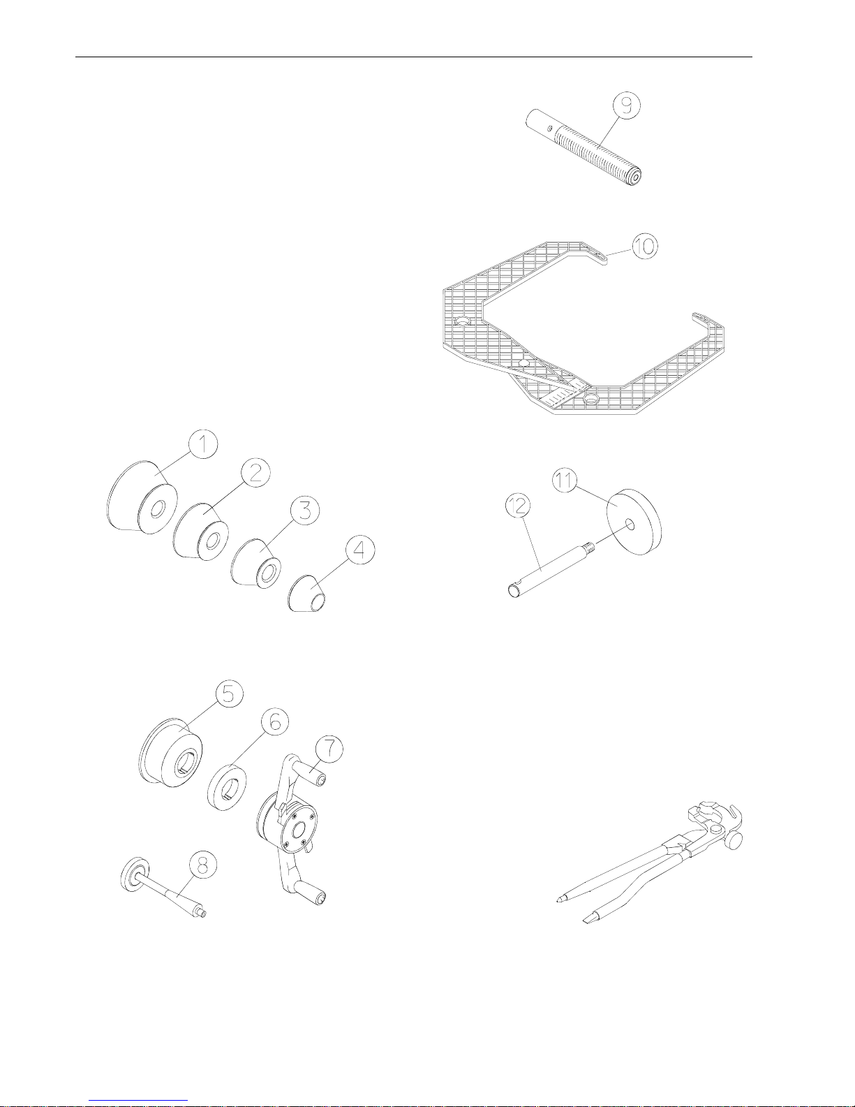
1.5 STANDARD ACCESSORIES
Standard accessories included with the VPI System I
are:
1 EAM0003J08A Cone, 85-132 mm / 3.3”-5.2”
2 EAM0003J07A Cone, 71-99 mm / 2.8”-3.9”
3 EAM0003J06A Cone, 56-84 mm / 2.2”-3.3”
4 EAM0003J05A Cone, 43-63 mm / 1.7” - 2.5”
5 8 - 02040A2 Cup - Pressure
6 8 - 02040A1 Disk - Pressure
7 8 - 02140A Quick Nut
8 EAM0005D40A Weight - Calibration
9 EAM0005D15A Stub Shaft
10 EAA0247G21A Caliper - Rim Width
11 EAC0060G02A Flange - Cover, Hook
12 EAM0006G01A Pin - Accessory
Figure 1
Figure 2
1.6 OPTIONAL ACCESSORIES
Weight Pliers P/N 26 (Figure3).
Versatile weight hammer/plier. In addition to hammering on weight and used weight removal, the
26
hammer/plier can be used to reshape worn weight
clips and trim weight to size.
model
Figure 3
Page 6
John Bean VPI System I Operators Manual
PRE-INSTALLATION CONSIDERATIONS
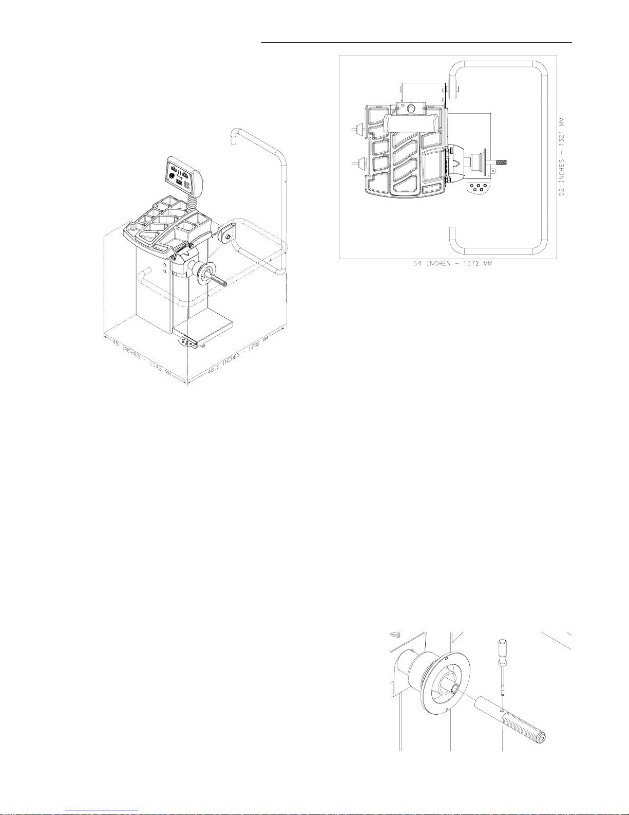
1.7 DIMENSIONS OF THE MACHINE
Figure 5 - Recommended Work Area
1.9 INSTALLATION INSTRUCTIONS
CAUTION! CAREFULLY REMOVE THE BALANCER
FROM THE PALLET.
Remove the hardware that secures the machine to
the pallet and slide the balancer onto the floor where
it is to be installed.
THE UNIT IS HEAVY AND THE WEIGHT IS NOT
EVENLY DISTRIBUTED.
Figure 4 - Actual Footprint Dimensions.
1.8 REQUIRED INSTALLATION AREA
Make sure that from the operating position the user can
see all of the machine and the surrounding area.
The operator should prevent non authorized persons
and/or objects from entering the area which may create potential hazards.
The machine should be installed on a stable level floor.
Do not install the machine on a uneven floor.
If the balancer is to be installed on a raised floor, the
floor must have a capacity of at least 110lbs per sq ft.
(5000 N/m² - 500 kg/m²).
It is not required to secure the machine to the floor.
Install the machine in a dry, covered area.
The installation of the machine requires a working area
of at least 54” x 52” (1372 x 1321 mm) (Figure5).
DO NOT LIFT THE BALANCER BY THE SHAFT.
DROPPING THE UNIT MAY CAUSE PERSONAL INJURY OR EQUIPMENT DAMAGE.
2.0 BALANCER INSTALLATION
Mounting the Shaft Adapter
IMPORTANT!
CHECK THAT THE SURFACES ARE PERFECTLY
CLEAN AND NOT DAMAGED. AN INCORRECT
MOUNTING MAY RESULT IN SIGNIFICANT IMBALANCE.
A. Mount the threaded shaft onto the arbor of the bal-
ancer. Tighten firmly using a screwdriver. (Figure 6).
Figure 6
Page 7

B. Install the accessory pins (Figure 7). Tighten firmly.
Figure 8
2.2 ELECTRIC INSTALLATION
ANY ELECTRICAL WIRING MUST BE PERFORMED BY LICENSED PERSONNEL.
ALL SERVICE MUST BE PERFORMED BY AN
AUTHORIZED SERVICE TECHNICIAN.
Figure 7
C. Place cones and other accessories onto the accessory pins.
2.1 HOOD GUARD INSTALLATION
The safety hood guard is standard equipment and
must be installed prior to use.
Refer to Figure 8 for hood guard installation.
Parts Required:
(1) Hood Guard Assembly
(1) 3/8” - 16 x 2” HHCS
(1) 3/8” x 16 Keps
Position the hood guard in the raised (up) position.
Slide the hood guard support tube over the frame pivot
shaft protruding from the right side of the balancer cabinet.
Line up the mounting holes in both the pivot shaft and
the guard support tube. Secure the guard with 3/8” hardware.
Check on the plate of the machine that the electrical
specifications of the power source are the same as the
machine. The machine uses 115VAC, 50-60Hz, 1Ph,
8.0 Ampere. 230VAC units are available if required.
NOTE:
Any electrical outlet installation must be verified
by a licensed electrician before connecting the balancer.
NOTE:
This machine performs a self-test routine on startup. There will be a delay of several seconds before
the display is activated.
2.3 USER CALIBRATION
Perform the user calibration procedures as instructed
on page 21 and 22 of this manual before placing the
machine in service.
Page 8

John Bean VPI System I Operators Manual
3.0 TERMINOLOGY
Figure 9
Before using the wheel balancer it is suggested that
you become familiar with the terminology and features
of the machine’s components. Refer to Figures 9 and
10 for identification and location.
1. Inside Weight Amount and Function Display
Window - Shows inside or left weight amount and
various operation messages.
2. Position Indicator LEDs - Displays the location
for wheel weight placement.
3. Outside Weight Amount and Function Display
Window Shows outside or right weight amount and
various operation messages.
4. Weight Mode and Placement Display - Displays
a pictorial reference of the chosen balance mode.
5. Function Button - Used to activate the various
functions. Press this button followed by pressing
the
up
or
down
arrow buttons until the desired number is displayed. Press the “Enter” button to active
the function.
6. Enter - This key activates whatever selection has
been requested, it also spins the wheel if guard
frame is down.
7. Up and Down Value - Buttons are used to raise or
lower displayed values for parameter entry or function code activation.
NOTE: Rotating the shaft in either direction will
also vary displayed values.
8. Cancel - Pressing this key interrupts any process.
9. Mode Selection - A series of placement locations
for custom weight location. Useful for the wide variety of custom wheels on today's market.
10. Rim Width - Press this key to enter the rim width.
Use the rim width calipers for measurement.
11. Rim Diameter - Enter the rim diameter after pressing this key. Read the size stated on the tire sidewall.
12. ALU-S and Spoke Mode - Activates the ALU-S or
Spoke Mode. Each time this button is pressed programming toggles between the two.
13. Rim Offset - This key is used to enter the rim offset
position using the numbers from the distance gauge.
14. Multi-Operator Selection - This key toggles between four operators designated as a, b, c, and d.
Wheel parameters are recalled upon command.
15. Display - Easy to read, user friendly display featuring large LEDs and one button functions.
16. Weight Storage Tray - Generous storage for a
variety of weight profiles and sizes as well as built
in storage pockets for the standard centering cones.
17. Accessory Storage - Four sturdy side mounted
pegs are supplied for storage of additional accessories.
18. Foot Operated Shaft Lock - A foot operated shaft
lock is used to stabilize the shaft during the weight
placement process.
19. Shaft Adapter - A common 40 mm size shaft is
used. The easily removable shaft can be replaced
for service or during use of certain wheel adapters.
20. Wheel Guard - The standard wheel guard is a
safety feature for prevention of operator injury in
the event of loose weights, debris or wheel mounting failure. The balancer is programed to spin upon
guard closure as well as brake when the guard is
raised.
21. Semi-Automatic Parameter Arm - Rim distance
is automatically input with the SAPE. The SAPE is
also used in several procedures for determining
accurate rim profiles.
Page 9

4.0 OPERATION OF THE BALANCER
WARNING: For operator safety please read
and follow the precautions outlined on
pages 1 and 2 of this manual.
NOTE: Read all instructions before proceeding with operation of the balancer.
Before starting any balancing procedure it is very important that the wheel is mounted on the machine with
the proper adaptors. An incorrect centering of the wheel
will result in considerable imbalance.
There are many types of wheels and John Bean supplies adaptors of good quality and durability for the large
majority. However if you meet special wheels which may
require a specific adaptor, call your authorized John
Bean distributor.
All balancer functions are input into the main computer
through the large easy to read touch panel. Although
each wheel tire assembly differ in some ways all balancing jobs require basically the same procedure. The
order of events to take place are:
1. Inspection of the wheel/tire assembly
2. Mounting wheel onto shaft or adapter
3. Selection of Balancing Mode and Preferences
4. Entry of wheel parameters
5. Spinning the wheel
6. Applying the recommended weight
7. Check spin if desired
8. Dismounting the wheel
The following operation instructions will follow the basic outline above.
4.1 CHECK LIST - INSPECTION
Observe Before Balancing Wheel
1. Check for proper air pressure. If not correct, inflate to
correct pressure.
Rims may be divided into these major groups:
1. Car rims with a true center hole.
2. Car rims without a center hole.
3. Car rims with an untrue center hole.
4. Light truck rims.
4.2.1 Standard Wheels (back cone mount)
Mount the wheel as detailed below in Figure 11:
2. Check for any foreign material inside tire. If present,
remove before balancing tire.
WATER IS FOREIGN MATERIAL!
3. Remove old weights — old weights may be improper
value or in wrong location.
4. Be sure tire and wheel are free of excessive dirt, rust
and large stones. Use wire brush on back side of wheel
if necessary.
4.2 WHEEL MOUNTING
Nearly all standard wheels and many alloy wheels have
accurately machined center holes, and they should be
mounted with center cones. Accurate balancing depends on accurate mounting of the wheel and correct
seating of the cone in the pilot hole. Insure that the wheel
is centered on the shaft exactly as it will be mounted to
the vehicle.
Page 10
Figure 11
1. Mount proper cone against spring plate.
2. Mount wheel on shaft in the same manner as you
would on the car.
3. Mount pressure cup on shaft and place against
outside of wheel, follow with the Quick-nut.
4. Tighten Quick-nut securely with both hands. To
operate the Quick-nut pull the lock-unlock lever
(Figure 12). Slide the Quick-nut on the threaded
shaft. When in contact with the rim, release the
unlock lever and tighten firmly. To assist in
centering the wheel properly, rotate the wheel on
the shaft while tightening the quick nut.

John Bean VPI System I Operators Manual
Figure 12
!
FAILURE TO TIGHTEN WING NUT SECURELY
MAY RESULT IN SERIOUS PERSONAL INJURY.
DO NOT USE A HAMMER TO TIGHTEN THE
QUICK NUT.
TO RELEASE THE QUICK NUT, UNSCREW A
FEW TURNS TO REDUCE THE AXIAL PRESSURE, THEN PRESS THE UNLOCK LEVER AND
SLIDE AWAY FROM THE SHAFT.
4.3 MODE SELECTION
The majority of balancing takes place in the default 2plane dynamic mode which is displayed as "2 PL"
(location 1). Hammer-on clip weights will be placed on
both inside and outside of the rim edge. If required,
select an optional weight placement mode by pressing
the
Mode
button until the appropriate placement mode
is displayed.
4.3.1 WEIGHT PLACEMENT MODES
Before spinning the wheel (although it may be done afterwards) choose the appropriate balancing mode for
the wheel. To select the various placement modes press
the Mode button until placement LEDs indicate desired
placement position.
Indicator LEDs
Mode Button
5. Check that the wheel rotates true by turning the wheel
several revolutions while noting any excessive runout.
4.2.2 CENTERING LIGHT-TRUCK WHEELS
An optional offset spacer may be required for some light
truck wheels and reverse-offset wheels that must be
moved away from the balancer mounting flange. The
extension adaptor is often used with the 5-1/4 inch diameter light truck cone.
Install the spacer on the mounting flange, then mount
the wheel, using the front cone method (Figure 13)
The balancing modes available are:
A. DYNAMIC (two planes), suggested for all steel rims.
In this case the wheel weights must be clipped onto the
rim edges. This function is selected as a default and
the LEDs corresponding to the wheel weight location
are lit on (Figure15).
Figure 14
Figure 15
B. STATIC (single plane - Figure16). Suggested for nar-
row rims (3" or less). Use a single corrective weight
placed in the center of rim as illustrated in Figure 16.
Figure 13
Figure 16
Page 11

C. ALUMINUM MODES. Balancing using a combination of hammer-on and adhesive weights as shown in
Figures 17 thru 21.
Figure 17 ALU 1
Figure 18 ALU 2
4.4 SELECTING OPERATOR PREFERENCES
4.4.1 FINE BALANCING MODE
This balancer measures with the maximum precision
available all the time, 1g / 0.05 oz, however values below 5g / 0.25 oz are shown as zero while in the normal
operating mode. Values exceeding 5g / 0.25 oz are
rounded to the amount of the nearest commercial wheel
weight.
Press the F button followed by the
button to toggle the display resolution between 5g /
0.25 oz and 1g / 0.05 oz.
4.4.2 OUNCE/GRAMS CONVERSION
When the machine is first turned on it is preset to display the imbalance in ounces.
If the display in grams is desired, press the F button
followed by the
displayed”.
Repeat the procedure for converting back to ounces.
4.4.3 RIM DIAMETER IN MILLIMETERS
UP
or
Down
UP
or
Down
arrow
arrow button until “P 3” is
Figure 19 ALU 3
Figure 20 ALU 4
Figure 21 ALU 5
TO RETURN TO THE
ANY OF THE
cel/Stop.
ALU
PROGRAMS, JUST PRESS Can-
DYNAMIC
PROGRAM FROM
The rim diameter is normally displayed in inches, however if the value in millimeters is desired, press the
button followed by the
“P 7” is displayed”.
Repeat the above operation to convert back to inches.
Example: “dIA ICH” = inches
“dIA ---” = millimeters
4.4.4 OPERATOR SELECTION
Select the desired operator designated A,B,C,or D. The
EEWB304A Balancer can store wheel parameters of
four operators. The Operator button toggles between
the four operators with each depression.
UP
or
Down
arrow button until
F
Page 12

John Bean VPI System I Operators Manual
4.5 ENTER RIM PARAMETERS
4.5.1 Rim Distance (offset) - Move the rim off-
set arm to the edge of the rim, touch the pointer to
the rim edge as illustrated in Figure 22 and hold
steady for about a second. The beeper will sound
when the distance values are calculated and entered automatically. Return the arm to its fully in
and down position on the balancer. Do not allow
the measurement arm to "dangle" down in front of
the balancer.
4.5.3 Measure Rim Width using rim width
calipers. Measure wheel where corrective clip-on
weight would be applied, Figure 24. Enter the
measured width by pressing the
UP
or
Down
arrow button until the desired value appears in the
center display.
Figure 24
Figure 22
4.5.2 Rim Diameter Entry - Select the Manual
Diameter button (#11 page 9). Read the rim diameter marked on the sidewall of the tire (Figure
23). Enter the measured rim diameter by pressing
the
Diameter
row button until the desired value appears in the
button followed by the
UP
or
Down
ar-
right display.
4.5.3 Manual Parameter Entry
In the event of automatic gauge failure, the distance values can be input manually.
4.5.3.1 Manual Distance Entry - Move the distance gauge arm to touch the inner edge of the
wheel where weights are to be placed and observe
the reading on the scale of the distance gauge.
Press manual Wheel
followed by pressing the
Offset
UP
button (#13 page 9)
or
Down
arrow button
until value is displayed in the left display window.
NOTE: For a more precise balancing of perfor-
mance wheels, an “ALU-S” Mode is available for
precision determination of wheel parameters. This
feature allows exacting placement of corrective
weights as well. See
Page 18
for detailed instruc-
tions.
NOTE: The parameter arm must be in the Home
rest position when the balancer is powered up.
Thisestablishes the arm starting position.
Figure 23
Page 13

4.6 CORRECTION OF THE IMBALANCE
NOTE: Before spinning the wheel make sure proper
eye protection is worn by all personnel in the vicinity of
the balancer.
A. Spin the wheel by lowering the wheel guard or by
pressing the
is completed the wheel will stop automatically and the
imbalance values will appear on the LED’s.
Enter
button. When the balancing cycle
NOTE: If this situation is repeated, your machine may
be out of calibration and a calibration operation might
be required as instructed on page 21.
ALU
D. If an
weights have been placed in accordance to the program chosen.
E. Check that the quick nut is tight and that the wheel is
not slipping against the backing collar.
function was selected ensure that the wheel
NOTE: Do not use the foot operated shaft lock as a
brake, it is intended to be used only to prevent shaft
rotation while placing corrective weights.
B. Read the imbalance value on the outer display. Values are displayed in ounces but can be displayed in
grams if required and are automatically rounded to the
nearest commercial wheel weight.
4.6.1 PLACING THE CORRECTIVE WEIGHT
Raise the wheel guard and turn the wheel until the displays of the outer plane imbalance position indicator
are illuminated green. Apply the wheel weight at twelve
o’clock position. Use the foot operated shaft lock to prevent shaft rotation while placing weights.
C. Correct the imbalance on the inner plane in the same
manner.
4.7 VERIFICATION OF THE RESULTS
Lower the wheel guard to spin the wheel again and
check that the readout is “0.00” “0.00” If a residual
imbalance is displayed:
A. Check the rim parameters, if entered value is incorrect, correct as needed. Imbalance values will be recomputed after re-spinning wheel.
B. Check if the balancing mode selected is the most
appropriate. If not, choose the right mode and respin.
C. The wheel weight could have been placed at a wrong
position. To check this, position the wheel at the correction position for the outer plane. If the wheel weight
previously attached is in sector ‘L’ or ‘R’ ( Figure25),
move the wheel weight up about 1” (2.54cm).
If the wheel weight is in sector ‘D’ cut a piece of the
wheel weight of an approximate value corresponding
to the value shown on the right display, or replace the
wheel weight with a lighter one.
If the wheel weight is in sector ‘U’ add a weight of value
indicated by the display or replace the wheel weight
with a heavier one. Repeat the same operation for the
inner plane.
F. Check that the wheel and adaptors are clean.
Figure 25
4.8 VIBRATION PROBLEMS
If vibration is still present after balancing, check the following possible sources of vibration:
1. Stones caught in the tire tread.
2. Tire slippage on the wheel.
3. Incorrectly mounted wheel.
4. Imbalanced wheel covers.
5. Excessive radial or lateral runout in the tire or
wheel.
6. Damaged wheel bolt holes.
7. Worn universal joints.
8. Imbalanced brake rotors or drums.
9. Worn or damaged balancer accessories.
Page 14

John Bean VPI System I Operators Manual
5.0 TIRE MATCHING PROGRAM - F90
Tire matching assists the user in determining the best
possible mating of the tire and rim. The mating of tire
and wheel normally allows the least amount of additional weight required for balancing and total runout.
The matching program is helpful when:
• Excessive radial runout is noticed.
• The balancer calls for weights in excess of 2 oz. on
either plane in the
The VPI System I computer wheel balancer features a
matching program capable of two levels of resolution:
Dynamic
for optimum rim and tire matching.
Static
rectional tread and cannot be reversed on the rim.
INSTRUCTIONS:
, to rotate
, when the tire has an ornate sidewall or di-
Dynamic
and
mode.
reverse the tire on the rim
Figure 26 - Step 1, valve top, press "F"
1. Press the "F" button dollowed by pressing the
Down
release the "F" button.
When activated the machine displays "--- ACH" for one
second followed by "VAL tOP". This instructs the operator to rotate the wheel so the inflation valve is at 12
o'clock. See
position, the display will then read "SPN 1 ".
NOTE: The F button can be pressed more than once,
every time the F button is pressed, the valve position is
remembered by machine as a reference point.
2. Lower the wheel guard to spin the wheel, when the
shaft reaches the balancing speed, the display reads
"ACH 1" accompanied with a short beep.
3. After spinning the shaft brake engages and the display reads "tur tir" and "CrS tOP" alternatively.
(1) The operator should turn the wheel and mark an X
at the 12 o'clock when the valve is at the 6 o'clock position.
arrow button until the display reads "F" “90”,
Figure
Figure
27
26. Press "F" to store the valve
UP
or
Figure 27 - Step 2, valve at bottom,
mark top of tire with X, press "F"
(2) Remove the wheel assembly from the balancer and
deflate and rotate the tire on the rim so the valve points
to the cross mark on tire as shown in
4. After inflating the tire and remounting on shaft, press
F Button. The machine displays "VAL tOP" again. Op-
erator should turn the wheel so the valve is at 12 o'clock.
Press the "F" button to program the valve position.
Figure
28
Figure 28 - Step 3, rotate tire on wheel so the valve and
X mark line up. Rotate assembly to TDC, press "F".
Page 15

NOTE: The "F" button can be pressed as often as necessary, with every press the machine updates the
memory of the valve position.
5. The machine displays "SPN 2 ". Lower the wheel
guard to spin the wheel, when the shaft reaches the
balancing speed, machine displays "ACH 2" along with
a beep.
6. Once the spin cycle is complete, the display reads
"CAL CUL" for one second. Machine calculates the
results based on the previous two spins.
From this point, there are three possible procedures to
conclude the match balance routine. These 3 procedures are quite different depending on the results of
calculation.
Procedure 1
The imbalance measured in spin 2 has been reduced
to an acceptable amount, less than 2 oz, and it will not
be necessary to continue match balance. The display
reads "ACH FIN" for one second, and then proceeds
to the normal two-plane balancing mode and displays
the weight imbalance amount and its position for both
planes.
Figure 29
Figure 30
Procedure 2
Due to a large amount of remaining imbalance the operator can continue match mount. Machine displays
"CrS” “r" and "tur” “tir" alternatively. This instructs the
operator to turn the wheel and make a double cross
mark (XX) on the right side of the tire at 12 o'clock position when the right center position LED turns to green.
See Figure 29.
NOTE: If you do not intend to continue minimization,
you can press the Cancel/Stop Button
If the Cancel/Stop Button is pressed now, machine displays "Qit Qit" for one and half second to remind operator whether he wants to quit optimization or not. If
one presses Cancel/Stop Button immediately, the program goes to procedure 1. If not, after one and half
second, machine returns to the optimization procedure.
To continue with optimization: Deflate the tire and then
turn the valve to point the XX mark on the tire. Remount
tire/wheel onto shaft, press "F" when ready to continue.
1. The machine displays "VAL tOP". Turn the wheel
so the valve is at top position. (12 o'clock) and then
press F Button. The machine stores the valve position.
See Figure 30.
2. The machine displays "SPN 3 ". Lower wheel guard
to spin shaft. Machine displays "ACH 3 ".
Page 16

John Bean VPI System I Operators Manual
3. Display will read "ACH CHC" for one second. Balancing results are checked whether or not the matching balancing has been achieved.
4. There are two results that could been given by the
previous step:
1 -
Match Balance failure
"FAI L " for one second and then goes to idle state.
2 -
Match Balance is successful
"ACH FIN" for one second and then goes to normal
two plane balancing mode. Machine displays the
recalculated weights and their position taking the
matching results into account.
Procedure 3
1. Machine displays "CrS L" and "FLP tir" alterna-
tively. When the left center position LED turns to green
this instructs the operator to turn the wheel and mark a
XX on the left side of the tire at 12 o'clock position.
2. If the tire cannot be flipped, press the Cancel/Stop
Button to force machine to procedure 2.
Calculations may not allow continuation of the matching process. If this is the case, machine displays "NO
NO " for one and half second. If the operator does not
respond the machine returns to above state after one
and half second.
. Machine displays:
. Machine displays:
7. Lower the wheel guard to spin the shaft. Machine
displays "ACH 3 " while collecting data. Do not disturb
the machine while it is acquiring data.
8. When balancing is complete, the machine displays
"ACH CHC" for one second. Machine processes the
balancing results to check whether or not the matching
balancing has been achieved.
9. There are two results could been given by the previous step.
1.
Matching balancing failure
"FAI L " for one second and then goes to idle state.
2 -
Match Balance is successful
"ACH FIN" for one second and then goes to normal
two plane balancing mode. Machine displays the
recalculated weights and their position taking the
matching results into account.
. Machine displays:
. Machine displays:
6.0 OPTIMIZATION ROUTINE- F91
The Optimization Routine is very similar to that of the
Match Mount Program (F90). The main difference is
that operation begins with a bare rim instead of a rimtire assembly. Follow instructions as detailed for in chapter 5.0 for F90.
If the Cancel/Stop Button is pressed within one and half
second, machine will display "Qit Qit" for one and half
seconds indicating cancelation of optimization returning the machine to normal balancing modes.
If optimization is to be continued with flipping tire, proceed as described below.
3. Deflate the tire then flip, turning the valve to point the
XX mark on the tire (as in procedure 2).
4. Inflate the tire and mount it to shaft again. Press the
“F” Button.
5. The machine displays "VAL tOP". Turn the wheel to
make valve at top position. (12 o'clock) and then press
"F" button. The machine will store the valve position.
6. The machine displays "SPN 3 ".
NOTE: The F Button can be pressed as often as nec-
essary, with every press the machine updates the
memory of the valve position.
Page 17

7.0 ALU-S MODE
This is a mode similar to ALU mode 2 and 3. The difference is that the distance and width parameters are accurately defined for a more exacting weight placement,
therefore improving the likelihood of a single spin balance. Follow the procedures below:
1. Press the Alu-s/Spoke button to activate the ALU-S
mode, the display will read " ALU - S".
2. Extend the rim offset gauge arm and touch the position of the left weight position. See Figure 31. The
display will read “d - I”. The high tone will sound when
dimension is entered. Return the gauge arm to the rest
position, a low pitch tone will indicate when it is OK to
proceed.
3. Move the parameter arm to the right weight position, the machine displays “d - 2” as the arm is moved.
See Figure 32. The high tone will sound when dimensions are entered. Return the gauge arm to the rest
position, a low pitch tone will indicate when it is OK to
proceed.
Figure 31
4. Enter the measured rim diameter by pressing the
Diameter
button or by rotating the shaft until the desired value
appears in the right display.
5. Lower the wheel guard or press “Enter” to spin the
wheel. The display will read “ALU” during the spin cycle.
6. After spinning, the machine displays both the left
and right plane imbalance weight and position with its
color LEDs.
Rotate the wheel until the left Green LED indicates correct position for the left correction weight.
7. Extend the gauge arm. The left display shows the
weight amount to be applied, the right display shows
the distance the gauge arm has to travel to get to the
correction plane. A high beep will sound when the correct position is reached, at the same time the right display will read “0“ when the proper position is attained.
A reading of “- - -“ in the distance window means the
gauge arm is over extended. Apply the weight amount
indicated in the left window using the tape weight applicator mounted on the SAPE extension.
Return the gauge arm to its home position.
8. The right plane correction weight will be applied next
as in step 7 above. The steps outlines are:
button followed by the
UP
or
Down
arrow
- Extend the arm until “0” is indicated in left window.
Figure 32
- Position the wheel in the weight application position
- Apply the displayed weight.
NOTE: Returning the gauge arm to the “Home” posi-
tion toggles between the left and right correction plane.
NOTE: To exit ALU-S mode and return to two plane
DYN (dynamic) mode press “Mode” button. The machine displays "ALU OFF" for one second and then
enters idle state in the 2-pl DYN mode
NOTE: Inspect the rim and available weights and use
good judgement in your selection. Weights should not
interfere with any suspension parts or make contact
during rotation. If a weight does make contact, use an
alternate location and select an appropriate mode.
Page 18

John Bean VPI System I Operators Manual
8.0 Spoke Balancing Mode
A standard dynamic balance places compenstation weight in two
planes, inner and outer, at the top dead center 180 degrees of
each plane of calculated imbalance. Sometimes the outide weight
placement may be unsightly on a custom wheel. See Figure 33.
The Spoke Mode is designed to “hide” outer plane corrective
weight by placing the required weight behind selected spokes in
order to retain the esthetic appeal of the wheel.
1. Press the Alu-s/Spoke button until “SPO” is displayed, the
display will read " SPO " when activated.
2. Enter left plane distance using the SAPE as you would a
dynamic 2-plane or ALU-S balance.
Figure 33
3. Move the parameter arm to the right weight position, the
machine displays “d - 2” as the arm is moved.
4. Enter the measured rim diameter by pressing the
Down
arrow button or by rotating the shaft until the desired value
appears in the right display.
5. Press Enter, or, lower hood guard. The display will read
“SPO” while spinning. After Braking to a stop rotate the shaft to
the inside plane top dead center position indicated by the center
green LED. Extend the SAPE until the right reading says “0”,
place indicated weight in the position directed by the SAPE.
6. Rotate the wheel to the outside plane top dead center position indicated by the center green LED, press the "F" button to
indicate top dead center.
NOTE: Mark the tire to assist in referencing the corrective weight
top dead center.
7. The display will read "SPO I “. Locate the first spoke nearest to top dead center and rotate the wheel so that spoke is at
top dead center. See Figure 34. Press P to store first position.
8. The display will read “SPO 2 “. Locate the second closest
spoke to top dead center and rotate the wheel to the top dead
center position, press F Button again to store the position. See
Figure 35.
UP
or
X
Figure 34
X
Figure 35
9. The display will read “P -2” on its left window and the balance weight amount in right window. Place the weight amount
displayed at “position 2” behind the spoke, then rotate the wheel
to locate position 1. See Figure 36.
10. When position 1 is located, the balancer will beep. The display will read “P -1” in the left window and the weight amount on
right window. Place the weight amount displayed at “position 1”
behind the spoke.
11. Perform a check spin if desired.
X
Figure 36
Page 19

9.0 Split Weights - P92
The “Split Weight” function is used to split one large
weight to two smaller weights with 60% of original weight
and 33.6° away each direction from the original position. For instance, if the original unbalance weight is 3
oz, the weight is split into two 1.75 oz weights and placed
56.4° and 123.6° from the original larger value located
top dead center at 90 degrees. The minimum weight to
activate this function is 2 oz. The procedure is described
below. See Figure 37.
1. After balancing, the weight amounts are displayed
in left and right windows.
2. Enter F92, machine will display “SPL -L- “ or “SPL
-R-“ meaning which plane should be split.
3. Press the “STOP” button alternately to toggle between the left and right plane.
4. Once the desired plane is chosen, press the "F"
button. The machine splits the weight into two parts.
The split weight is 60% of the original weight. The
position is 33.6° from each side the original position.
Figure 37
5. If the displayed weight is less than 2 oz (56.7
grams), the machine will display “ NOT AVL” for
one second, and then resumes the normal display.
6. Pressing “STOP” cancels the split weight mode
and operation returns to normal. The operator can
check if the position of original weight is between
the two smaller weights.
7. Pressing the “STOP” button again, returns the
machjine to idle mode without weight amount or position display.
8. For a check spin, lower the hood guard or press
“SPIN” button.
Page 20

John Bean VPI System I Operators Manual
10.0 USER CALIBRATION
The VPI System I Balancer features a user calibration
program which requires only a few minutes to complete.
Perform this procedure when the balancer has been
moved, disturbed, or whenever accuracy is questioned.
Occasional field calibration will ensure years of reliable
service.
Follow these 3 simple steps:
1. Activate Calibration.
Press the F Button (#1 Figure 38) then press the UP/
Down buttons (#2 Figure 38) until the display reads "F"
“14”.
• Once F14 activates, the display will read
"CAL" " GAN" for one second.
• The display will then read "SPN" " 1 ".
• Mount a balanced wheel/tire to the shaft.
See Figure 39.
2. Spin shaft with balanced wheel only.
Lower the wheel guard or press enter to spin the shaft
with wheel/tire assembly. See Figure 39
• Displays "CAL" " 1 " as the machine is collecting
data and performing calculations. After taking data,
the shaft is automatically braked to a stopped.
• The display will read "SPN" " 2".
Figure 38
2
1
3. Spin shaft with calibration slug on the left side.
Mount calibration slug to inside edge of shaft mounting
plate as shown in Figure 40.
• Lower the wheel guard or press enter to spin the
shaft with slug and wheel/tire assembly.
• Displays "CAL" " 2" as the balancer is doing its
calculations. When complete, the shaft is automatically braked to a stop.
• The display will read "CAL" "FIN " when the second
step of calibration is FINished.
• If for some reason the calibration detected an error,
the display will read: "---" "---" after the shaft brakes.
NOTE: The balancer will not function until a valid calibration has been performed. Error messages will be
displayed in the event problems occur during the calibration process.
Figure 39
Figure 40
Page 21

Figure 40
Figure 41
11.0 Distance Gauge Calibration F80
1. Make sure the SAPE arm is in the home
position as shown in (Figure 40). NOTE:
Weight tray must be installed.
2. Press the “F” button followed by pressing the
“Up”
or
“Down”
button until the
display reads “F” “80”, press “EN-
TER” to continue.
3. The display will read “CAL ” “SAP” for
one second. This means CALibration of
SAPE. The display will then read “SAP”
“OUT”.
4. Gently pull the SAPE arm OUT until it is
fully extended, (Figure 41) hold it steady
for about 1 second or until beep.
5. Display will read “H” “POS” followed by
a beep. Return the arm to the home position (Figure 40). The display will read
“CAL End”.
Page 22

John Bean VPI System I Operators Manual
12.0 EXPLANATION OF PROGRAM CODES
Various functions and features can be programmed to
enhance operation. These programs are referred to as
“F Codes”. Activate the “F Code” programs by pressing and holding the
down arrow buttons or by turning the shaft until the desired number is displayed on the right display window.
User Codes are explained as follows:
F1 Toggle between normal and fine mode.
F3 Toggle switch between gram and ounce display
F7 Toggle switch of millimeter and inch for diameter
measurement
F12 The balancer has 4 counters that keeps track of total
number of cycles for a certain parameter. The balancer will automatically cycle through the counters
after P12 is pressed. The order of the counters are:
1. Display “Ctr ALL” for one second.
Counter number of all spins.
2. Display “Ctr CAL” for one second.
Counter number of spins since last calibration.
3. Display “Ctr SrV” for one second.
Counter number of service spins.
4. Display “Ctr USR” for one second.
Counter number of user spins.
F14 Shaft User Calibration by user
F18 ALU-S mode (press balancing mode button to exit
and back to DYN mode)
F43 Read or reset operator counters, reads or allows re-
set of all four operators. (A, B, C, D)
F44 Read or reset productivity of user. Display counter
number of default user only.
F90 Tire Matching mode
F91 Optimization
F Button
while depressing the up/
13.0 MAINTENANCE
!
BEFORE ANY MAINTENANCE OR REPAIRS ARE ATTEMPTED THE MACHINE
MUST BE DISCONNECTED FROM THE
ELECTRIC SUPPLY.
This balancer does not require any special maintenance,
but the following precautions are required:
A. Periodically wash all plastic parts with a glass
cleaner. Wipe with a dry cloth.
B. Clean all adapters regularly with a nonflammable liquid detergent all. Lubricate with a thin layer of oil.
C. Periodically perform a routine calibration as outlined
on pages 21and 22 of this manual.
14.0 TROUBLE SHOOTING
TROUBLE CAUSE REMEDY
When turning the machine on, No electric power Check the input voltage
the displays do not light Defect in the electric/electronic system Call the Equiserv service center
for assistance
The machine gives random readouts. Machine unstable on the floor Check that machine is stable
Water in the tire Remove water from tire.
Loose adaptor Tighten the adaptor firmly
Defective electronic board Call the Equiserv service center
for assistance
The machine does not stop after Defective electronic component Stop using the machine immedi
balancing cycle ately and call the Equiserv service
center for assistance
The balancer is slow to display when This machine performs a self-test routine This is a normal characteristic
powering machine up. on start-up. There will be a delay of several of the machine
seconds before the display is activated.
If the parameter arm ceases to Malfunction of the Parameter arm from Replace the Parameter arm or
properly measure rim distance either a failure of the electrical system manually enter the parameters
causing machine lockup. or harness connection failure. to continue operation.
Page 23

NOTES:

USA
John Bean
309 Exchange Avenue
Conway, Arkansas 72032
Tel.: (800) 362-8326 or (501) 450-1500
Fax: (501) 450-1585
FRANCE
John Bean
Snap-On Equipment France
Z.A. Du Vert Galant
15, rue de la Guivernone
BP 7175
95310 Saint Ouen L’Aumone
Tel: (33) 1-3448-5878
Fax: (33) 1-3448-5879
CANADA
John Bean
6500 Millcreek Drive
Mississauga, Ontario
Canada L5N 2W6
Tel: (905) 814-0114
Fax: (905) 814-0110
GERMANY
John Bean Auto Service Gerate
Division to Sun Electric Deutschland GMbH
Gewerbepark Sinn
D-35764 Sinn Herborner Str. 7-9
Tel: (49) 2772-9404-0
Fax: (49) 2772-94042-23
UNITED KINGDOM
Snap-On Equipment Ltd.
John Bean Equipment Group
Old Medow Road
Kings Lynn
Norfork
PE30 4WJ
Notice: The information contained in this document is subject to change without notice. John Bean
makes no warranty with regard to this material. John Bean shall not be liable for errors contained
herein or for incidental consequential damages in connection with furnishings, performance, or use of
this material.
This document contains proprietary information which is protected by copyright and patents. All rights
are reserved. No part of this document may be photocopied, reproduced, or translated without prior
written consent of John Bean.
is a registered trademark of Snap-on Technologies
Form 5787-1...pn ZEEWB504A....04/19/2001..wdc... copyright 2001 Printed in the USA
LATIN AMERICA
Snap-on Tools International, Ltd.
2801 80th Street
Kenosha, WI 53143
Tel: (262) 656-5003
Fax: (414) 656-1403
 Loading...