

Page 1
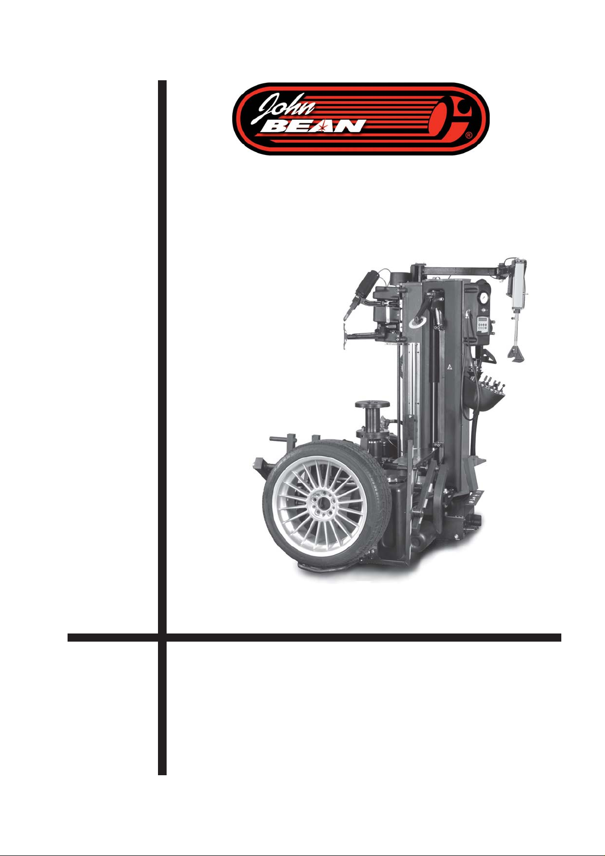
Bedienungsanleitung
Manuel de l’Operateur
Operator ’s Manual
Electro - Hydraulik - Pneumatic Automatic Tire Changer
Manuale d’Uso
Manuel del Operario
Manual do Operador
QUADRIGA 1000
QUADRIGA 1000 BB
ZEEWH536A03 Rev.E June 2010
Electro Pneumatic Car Tire Changer
Electro Pneumatic Car Tire Changer
Page 2
EC DECLARATION (Original document contained in Spare Parts Booklet)
DECLARATION CE (Le document original figurant dans le Liste des pièces détachées)
CE KONFORMITÄTSERKLÄRUNG (Originaldokument in der Ersatzteilliste enthaltenen)
DICHIARAZIONE CE (Originale contenuta nel Libretto Ricambi)
DECLARACIÓN CE (El original se encuentra en tabla de repuestos)
DECLARAÇÃO CE (O original está contida em Lista de peças)
- FAXIMILE -
ITA - DICHIARAZIONE CE DI CONFORMITA’
ENG - DECLARATION OF CE CONFORMITY
SPA - DECLARACIÓN CE DE CONFORMIDAD
POR - DECLARAÇÃO CE DE CONFORMIDADE
ALB - DEKLARATË KONFORMITETI KE
BUL - ȾȿɄɅȺɊȺɐɂə ɁȺ ɋɔɈɌȼȿɌɋɌȼɂȿ
CES - ES PROHLÁŠENÍ O SHODċ
HRV - DEKLARACIJA CE O PODOBNOSTI
DAN - EF-OVERENSSTEMMELSESERKLÆRING
EST - EÜ VASTA VUSDEKLARATSIOON
FIN - EY-VAATIMUSTENMUKAISUUSVAKUUTUS
ELL - ǻǾȁȍȈǾ CE ȈȊȂȂȅȇĭȍȈǾȈ
ISL - EB-SAMRÆMISYFIRLÝSING
LAV - ES ATBILSTƮBAS DEKLARƖCIJA
FRA - DECLARATION CE DE CONFORMITE
DEU - KONFORMITÄTSERKLÄRUNG
LIT - ATITIKTIES DEKLARACIJA
MKD - “EC” ȾȿɄɅȺɊȺɐɂȳȺ ɁȺ ɋɈɈȻɊȺɁɇɈɋɌ
MON - DEKLARACIJA CE O USKLAĈENOSTI
NLD - VERKLARING VAN OVEREENSTEMMING
POL - DEKLARACJA ZGODNOĝCI “CE”
RUM - DECLARAğIE DE CONFORMITATE CU NORMELE CE
SLO - ES VYHLÁSENIE O ZHODE
SLV - IZJAVA O SKLADNOSTI CE
SWE - EG-FÖRSÄKRAN OM ÖVERENSSTÄMMELSE
TUR - EC UYGUNLUK BEYANNAMESø
SPA - declara bajo su propia responsabilidad que la máquina: DESMONTADOR DE NEUMÁTICOS
LAV - apzin
POL - oĞwiadcza na wáasną odpowiedzialnoĞü, Īe maszyna: URZĄDZENIE DO ZDEJMOWANIA OPON
RUM - declarã pe propria rãspundere cã maúina: DISPOZITIV DE DEMONTAT CAUCIUCURI
SLO - vyhlasuje na vlastnú zodpovednosĢ, že strojové zariadenie: VYZÚVAýKA PNEUMATÍK
TUR - kendi sorumlulu÷u altında makinenin aúa÷ıda belirtilen yönetmeliklere uygun oldu÷unu beyan etmektedir: LASTøK SÖKÜCÜ
HUN - EK MEGFELELėSÉGI NYILATKOZAT
ITA
- dichiara sotto la propria responsabilità che la macchina:
ENG - takes full responsibility for declaring that the machine: TIRE CHANGER
POR - declara sob a própria responsabilidade que a máquina: DEMONTADORA DE PNEUS
FRA - déclare sous sa propre responsabilité que la machine : DEMONTE-PNEUS
DEU - erklärt auf eigene Verantwortung, dass die Maschine: REIFENMONTIERMASCHINE
ALB - deklaron nën përgjegjësinë e tij se makineria: ÇMONTUESE GOMASH
BUL - ɞɟɤɥɚɪɢɪɚ ɩɨɞ ɨɬɝɨɜɨɪɧɨɫɬ, ɱɟ ɦɚɲɢɧɚɬɚ: ɆȺɒɂɇȺ ɁȺ ȾȿɆɈɇɌȺɀ ɇȺ ȽɍɆɂ
CES - prohlašuje na vlastní zodpovČdnost, že strojní zaĜízení: ZOUVAýKA PNEUMATIK
HRV - izjavljuje pod vlastitom odgovornošüu da stroj: DEMONTIRAý GUMA
DAN - erklærer på eget ansvar, at maskinen: DÆKAFMONTERINGSMASKINE
EST - kinnitab omal vastutusel, et aparaat: REHVIVAHETUSSEADE
FIN - vakuuttaa omalla vastuullaan, että kone: RENKAANVAIHTOKONE
ELL - įȘȜȫȞİȚ ȣʌİȪșȣȞĮ ȩIJȚ Ș µȘȤĮȞȒ: ȂȅȋȁȅȈ ǹĭǹǿȇǼȈǾȈ ǹǼȇȅĬǹȁǹȂ ȅȊ
ISL - lýsir því yfir á eigin ábyrgð að bíllinn: AFFELGUN ARVÉL
Ɨdamies savu atbildƯbu apliecina, ka mašƯna/iekƗrta: RIEPU MONTÂÞAS IEKÂRTA
LIT - prisiimdama atsakomybĊ skelbia, kad mašina: PADANGØ KEITIMO PRIETAISAS
MKD - ɢɡʁɚɜɭɜɚ ɩɨɞ ɫɜɨʁɚ ɨɞɝɨɜɨɪɧɨɫɬ ɞɟɤɚ ɦɚɲɢɧɚɬɚ: ȾȿɆɈɇɌɂɊȺɑ ɇȺ ȽɍɆɂ
MON - izjavljuje pod vlastitom odgovorošüu da mašina: DEMONTIRKA GUMA
NLD - verklaart voor eigen verantwoordelijkheid dat de machine: BANDENLICHTER
SLV - pod lastno odgovornostjo izjavljamo, da je stroj: SNEMALEC GUM
SWE - försäkrar under eget ansvar att maskinen: DÄCKMONTERINGSMASKIN
HUN - a saját felel
Snap-on Equipment Srl
Via Provinciale per Carpi, 33
42015 Correggio (RE) Italy
FF
F
Ęssége tudatában kijelenti, hogy a gép: GUMISZERELė
SMONTAGOMME
AXIMILEAXIMILE
AXIMILE
AXIMILEAXIMILE
FF
JOHN BEAN JOHN BEAN
ITA - è conforme a tutte le disposizioni pertinenti delle seguenti direttive:
ENG - complies with all the relevant regulations in the following directives:
SPA - es conforme con todas las disposiciones pertinentes a las siguientes directivas:
POR - satisfaz todas as disposições relevantes das seguintes directivas:
FRA - est conforme à toutes les dispositions pertinentes des directives suivantes :
DEU - Allen zu folgenden Richtlinien gehörenden Bestimmungen entspricht:
ALB - është konform me të gjitha dispozitat që kanë të bëjnë me direktivat e mëposhtme:
BUL - ɫɴɨɬɜɟɬɫɬɜɚ ɧɚ ɜɫɢɱɤɢ ɪɚɡɩɨɪɟɞɛɢ, ɫɴɞɴɪɠɚɳɢ ɫɟ ɜ ɫɥɟɞɜɚɳɢɬɟ ɞɢɪɟɤɬɢɜɢ:
CES - vyhovuje všem požadavkĤm, které se vztahují na následující smČrnice:
HRV - udovoljava svim relevantnim odredbama slijedeüih smjernica:
DAN - er i overensstemmelse med bestemmelserne i følgende direktiver:
EST - vastab järgmiste direktiivide kõikidele asjassepuutuvatele sätetele:
FIN - on seuraavien direktiivien asiaankuuluvien säännösten mukainen:
ELL - İȓȞĮȚ ıȪµijȦȞȠ µİ ȩȜİȢ IJȚȢ ʌȡȠȕȜȑȥİȚȢ ıȤİIJȚțȑȢ µİ IJȚȢ ĮțȩȜȠȣșİȢ ȠįȘȖȓİȢ:
ISL - er í samræmi við allar viðeigandi tilskipanir eftirfarandi reglugerða:
LAV - atbilst visiem attiecƯgajiem noteikumiem šƗdƗs direktƯvƗs:
LIT - atitinka visus toliau nurodytǐ direktyvǐ reikalavimus:
MKD - ɟ ɜɨ
MON - je u skladu sa svim relevantnim odredbama sledeüih direktiva:
NLD - overeenstemt met alle toepasselijke voorschriften van de volgende richtlijnen:
POL - jest zgodna (jest zgodny) ze wszystkimi zarządzeniami zawartymi w nastĊpujących dyrektywach:
SLO - vyhovuje všetkým požiadavkám, vzĢahujúcim sa na nasledujúce smernice:
SLV - v skladu z vsemi predpisi, ki se nanašajo na naslednje direktive:
SWE - överensstämmer med alla bestämmelser tillhörande följande direktiv:
TUR - aúa÷ıda belirtilen yönetmeliklere iliúkin tüm hükümlere uygundur:
HUN - megfelel a következĘ irányelvekbe foglalt, valamennyi rendelkezésnek:
ITA-Il Responsabile dell’Ufficio Tecnico è autorizzato a costituire il fascicolo tecnico di cui all’allegato VII lettera A della direttiva
2006/42/CE.
ENG-The Manager of the Technical Office is authorised to compile a technical leaflet in compliance with appendix VII, letter A, of the 2006/42/CE directive.
SPA-El Responsable del Departamento Técnico está autorizado a constituir el fascículo técnico indicado en el anexo VII letra A de la directiva 2006/42/CE.
POR-O Responsável do Gabinete Técnico está autorizado a compilar o processo técnico, referido no anexo VII alínea A da directiva 2006/42/CE.
FRA-Le Responsable du Bureau Technique est autorisé à constituer le fascicule technique visé sous l’annexe VII lettre A de la directive 2006/42/CE.
DEU-Der Leiter der technischen Abteilung ist bevollmächtigt, die technischen Unterlagen zu erstellen (siehe Anhang VII, Buchstabe A der Richtlinie 2006/42/CE.
ALB-Përgjegjësi i Zyrës Teknike është i autorizuar të realizojë fashikullin teknik sipas dokumentit bashkëngjitur VII germa A e direktivës 2006/42/KE.
BUL-Ɉɬɝɨɜɨɪɧɢɤɴɬ ɧɚ Ɍɟɯɧɢɱɟɫɤɢɹ ɨɬɞɟɥ ɟ ɭɩɴɥɧɨɦɨɳɟ ɧ ɞɚ ɫɴɫɬɚɜɢ ɬɟɯɧɢɱɟɫɤɚɬɚ ɛɪɨɲɭɪɚ ɜ ɫɴɨɬɜɟɬɫɬɜɢɟ ɫ ɉɪɢɥɨɠɟɧɢɟ VII, ɛɭɤɜɚ „A” ɧɚ Ⱦɢɪɟɤɬɢɜɚ
2006/42/Eɋ.
CES-ZodpovČdný pracovník technického oddČlení je oprávnČný vypracovat technickou dokumentaci podle pĜílohy VII þásti A SmČrnice 2006/42/ES.
HRV-Odgovorna osoba Tehniþkog ureda je ovlaštena ustrojiti tehniþki svezak kako se vidi u dodatku VII slovo A smjernice 2006/42/CE.
DAN-Chefen i den tekniske afdeling har tilladelse til udarbejdelse af den tekniske dokumentation jf. bilag VII litra A i direktivet 2006/42/EF.
EST-Tehnoosakonna vastutav töötaja on volitatud koostama tehnilise toimiku vastavalt direktiivi 2006/42/EÜ VII lisa osale A.
FIN-Teknisen toimiston vastuuhenkilö on valtuutettu kokoamaan tekninen eritelmä direktiivin 2006/42/EY liitteen VII kohdan A mukai
ELL-ȅ ȊʌİȪșȣȞȠȢ IJȠȣ ȉİȤȞȚțȠȪ īȡĮijİȓȠȣ İȓȞĮȚ İȟȠȣıȚȠįȠIJȘµ
ISL-Ábyrgðarmanni tækniskrifstofunnar er heimilt að gera tækniskjalið samkvæmt A-lið VII. viðauka í reglugerð 2006/42/EB.
LAV-TehniskƗs nodaƺas vadƯtƗjs ir pilnvarots sastƗdƯt tehnisko dokumentƗciju atbilstoši ES direktƯvas 2006/42/EK VII pielikuma A iedaƺai.
LIT-už techninƳ skyriǐ atsakingas asmuo yra Ƴgaliotas sudaryti techninĊ bylą, kurios sudarymo tvarka nurodyta Direktyvos 2006/42/EB VII priedo A dalyje.
MKD-Ɉɞɝɨɜɨɪɧɢɨɬ ɧɚ ɬɟɯɧɢɱɤɢɨɬ ɨɞɞɟɥ ɟ ɨɜɥɚɫɬɟɧ
MON-Odgovorno lice Tehniþkog ureda je ovlašteno da sastavi tehniþku fasciklu kako se vidi u dodatku VII slovo A direktive 2006/42/CE.
NLD-Het Hoofd van de Technische Afdeling is gemachtigd om het technisch dossier samen te stellen waarover in Bijlage VII, afdeling A, van de richtlijn 2006/42/EG.
POL-Kierownik Biura Projektowego jest upowaĪniony do zaáoĪenia skoroszytu technicznego, o którym mowa w Zaáączniku VII litera A dyrektywy 2006/42/UE.
RUM-Responsabilul Biroului Tehnic este autorizat sã întocmeascã dosarul tehnic prevãzut în anexa VII litera A din directiva 2006/42/CE privind echipamentele tehnice.
SLO-Zodpovedný pracovník technického oddelenia je oprávnený vypracovaĢ technickú dokumentáciu podĐa prílohy VII þasti A Smernice 2006/42/ES.
SLV-Vodja tehniènega urada je pooblašèena za sestavo tehniène mape, kot navedeno v prilogi VII, èrka A direktive 2006/42/ES.
SWE-Ansvarig på det tekniska kontoret har behörighet att sammanställa medföljande teknisk dokumentation i enlighet med avsnitt A i bilaga VII i direktiv 2006/42/EG.
TUR-Teknik Ofis Sorumlusu 2006/42/EC Yönetmeli÷i’nin VII. ekinin A harfinde belirtilen teknik dosyayı hazırlamaya yetkilidir.
HUN-A MĦszaki Iroda IrodavezetĘje feljogosított a 2006/42/EK irányelv A részének VII. Mellékletében meghatározott, mĦszaki dokumentáció összeállítására.
ENG-Operations Manager SPA-Director Operativo POR-Director Operacional FRA-Directeur Opérationnel DEU-Betriebsleiter ALB-Drejtori Operativ BUL-Ɉɩɟɪɚɬɢɜɟɧ
ɞɢɪɟɤɬɨɪ CES-Výkonný Ĝeditel HRV-Operativni direktor DAN-Driftsleder EST-Tegevdirektor FIN-Operatiivinen johtaja ELL-ǼʌȚȤİȚȡȘıȚĮțȩȢ ǻȚİȣșȣȞIJȒȢ ISL-Starfandi
framkvæmdarstjóri LAV-OperatƯvais direktors LIT-Operacijǐ vadovas MKD-Ɉɩɟɪɚɬɢɜɟɧ ɞɢɪɟɤɬɨɪ MON-Operativni direktor NLD-Operationeel directeur POL-Dyrektor
Francesco Frezza
_______________________________________
2006/42/CE 2006/95/CE 2004/108/CE
ɞɚ ɝɨ ɫɨɫɬɚɜɢ ɬɟɯɧɢɱɤɢɨɬ ɩɪɢɪɚɱɧɢɤ ɞɚɞɟɧ ɜɨ ɩɪɢɥɨɝ VII ɩɢɫɦɨ A ɨɞ
Operatywny RUM-Director Operator
SLO-Výkonný riaditeĐ SLV-Operativni vodja SWE-Driftledare TUR-øúletme Müdürü HUN-Operatív Igazgató
ɫɨɝɥɚɫɧɨɫɬ ɫɨ ɫɢɬɟ ɧɨɪɦɢ ɨɞ ɫɥɟɞɧɢɜɟ ɞɢɪɟɤɬɢɜɢ:
ȑȞȠȢ ȞĮ ʌĮȡȐȟİȚ IJȠȞ IJİȤȞȚțȩ ijȐțİȜȠ ıȪµijȦȞĮ µİ IJȠ ıȣȞȘµµȑȞȠ VII ȖȡȐµµĮ A IJȘȢ ȠįȘȖȓĮȢ 2006/42/ǼȀ.
ITA-Direttore Operativo
date: __________________________________
sesti.
ɞɢɪɟɤɬɢɜɚɬɚ 2006/42/CE.
Correggio (RE) Italy,
2
QUADRIGA 1000/BB
Page 3
ENG -NOTES REGARDING DOCUMENTATION
FRA - NOTES SUR LA DOCUMENTATION
DEU -ANMERKUNGEN ZUR DOKUMENT ATION
NOTE SULLA DOCUMENTAZIONE - ITA
NOTAS SOBRE LA DOCUMENTACIÓN - SPA
NOTAS SOBRE A DOCUMENTAÇÃO - POR
Product aid publication:
TIRE CHANGER
publication de support au produit:
DEMONTE PNEUS
Zum Produkt gehörendes Dokument:
REIFENMONTIERGERÄT
original language edition in: ENGLISH - ITALIAN
langue d’origine de la publication: ANGLAIS - ITALIEN
Originalausgabe in: ENGLISH - ITALIENISCH
date of first publication: 06 / 2009
date de la première édition: 06 / 2009
Datum der Erstveröffentlichung: 06 / 2009
DOCUMENTATION SUPPLIED
DOCUMENTATION FOURNIE
GELIEFERTE DOKUMENTA TION
Pubblicazione di supporto al prodotto:
SMONTAGOMME
publicación de soporte al producto:
DESMONTA RUEDAS
Documentação de apoio ao produto:
MÁQUINA DE DESMONTAR PNEUS
edizione di lingua originale in: INGLESE - ITALIANO
edición original en idioma: INGLÉS - ITALIANO
edição original em: INGLÊS - IT ALIANO
data di prima pubblicazione: 06 / 2009
fecha de la primera publicación: 06 / 2009
data da primeira publicação: 06 / 2009
DOCUMENT AZIONE FORNIT A
DOCUMENT ACIÓN SUMINISTRADA
DOCUMENTAÇÃO FORNECIDA
ABB. DESCRIPTION CODE LANGUAGE
SIGLE DESCRIPTION CODE LANGUE
KENN. BESCHREIBUNG CODE SPRACHE
Operator’s Manual
OM Manuel de l’Opérateur ZEEWH536A03 ENG-FRA-DEU
Betriebsanleitung
Spare Parts Booklet ENG-FRA-DEU
SP Liste des pièces détachées TEEWH536A3
Ersatzteilliste ITA-SPA-POR
Contained in SP
Contenu dans SP
Teil der SP
EC DECLARATION
EC DECLARATION CE
CE KONFORMITÄTSERKLÄRUNG
Wiring Diagram
WD Schéma électrique
Schaltplan
Block Diagram
BD Schéma à blocs
Blockschema
Pneumatic Diagram
PD Schéma pneumatique
Pneumatikschema
SIGLA DESCRIZIONE CODICE LINGUA
SIGLA DESCRIPCIÓN CÓDIGO IDIOMA
SIGLA DESCRIÇÃO CÓDIGO IDIOMA
Manuale Operatore
OM Manual de Operador ZEEWH536A05 ITA-SPA-POR
Manual do Operador
Libretto Ricambi ENG-FRA-DEU
SP tabla de repuestos TEEWH536A3
Lista de peças ITA-SPA-POR
Contenuto in SP
Integradas en SP
Conteúdos em SP
DICHIARAZIONE CE
EC DECLARACIÓN CE
DECLARAÇÃO CE
Schema Elettrico
WD Esquema Eléctrico
Esquema Eléctrico
Schema a Blocchi
BD Esquemas en Bloques
Esquema em Blocos
Schema Pneumatico
PD Esquema Neumático
Esquema Pneumático
QUADRIGA 1000/BB
3
Page 4

UPDATING REPORTS
Contents
TABLE OF CONTENTS
List of changement from revision date:
A1 07/2009
Chapter: 7.1 section: Hint & Error
All languages translations completed.
List of changement from revision date:
A2 08/2009
Chapter: 3.1 section: Standard Accessories
Chapter: 3.2 section: Accessories on request
Accessories code correction.
List of changement from revision date:
B 12/2009
Chapter: 3.1 section: Standard Accessories
Accessories code correction for Kit fig. 3.1-2
Notes regarding documentation (ADDED).
List of changement from revision date:
C 04/2010
Chapter: 3.1 sect.: Standard Accessories
Accessories figure 3.1-2 - PCN 09G0243
Chap.:2.0 sect.:Specifications - PCN 10G0101
List of changement from revision date:
D 05/2010
PCN: 10G0027 - 10G0107
Chapter: 3.1 sect.: Standard Accessories
Faximile EC Declaration (Added).
Chap.:2.0 sect.:Specifications
List of changement from revision date:
E 06/2010
PCN: 10G0095
Chapter: 4.1 Completed instruction on key 7
Chapter: 5.2.1 Note at pag 80, 84 (added)
Chapter: 5.4 “Beading Tires with Inner Tubes”
(removed)
Chapter: 7.1 “HINT16, HINT17” (added)
Hofmann Address on Back Cover (changed)
INSTRUCTION: Safety Label Meanings
1.0 Safety
1.1 Format of this Manual
1.2 Safety Devices
1.3 Machine models
1.4 Identification data
2.0 Specifications
2.1 Conditions
3.0 Introduction
3.1 Standard accessories
3.2 Accessories on request
4.0 Layout
4.1 Controls
4.1.1 User Interface
4.2 Operating Automated Parts
4.3 Operating Parts
5.0 Operations
5.1 Locking Rims
5.1.3 Clamping - Unclamping the Wheel
5.2 Demounting and Mounting tires Automatically
5.2.1 Demounting
5.2.2 Mounting
5.3 Using the Bead pusher MH
5.4 Tires beading
6.0 Maintenance
6.1 Storage
7.0 Troubleshooting
7.1 System Messages
8.0 Disposing of the unit
8.1 Instructions for disposal in EC countries
9.0 Appendices
i Installation requirements
ii Transport, Unpacking, Handling - instructions
iii Installation procedures
iv Testing procedures
v Instructing the operator
Page 6
Page 12
Page 14
Page 16
Page 18
Page 18
Page 20
Page 20
Page 22
Page 26
Page 28
Page 30
Page 32
Page 32
Page 38
Page 54
Page 68
Page 70
Page 74
Page 76
Page 78
Page 82
Page 86
Page 88
Page 92
Page 96
Page 98
Page 102
Page 112
Page 112
Page 112
Page 116
Page 116
Page 120
Page 124
Page 124
IMPORTANT!!
PLEASE READ THIS MANUAL THOROUGHLY
BEFORE USING THE MACHINE
All the information in this manual has been supplied
by the producer of the equipment:
Snap-on Equipment Srl a unico socio
Via Provinciale per Carpi, 33
42015 CORREGGIO (RE) ITALY
Tel. +39-(0)522-733480
Fax +39-(0)522-733479
E-mail: [email protected]
Internet: http://www.gsboxer.com
Operator’s Manual
QUADRIGA 1000/BB
4
Page 5

Table des matieres
Inhalt
TABLE DES MATIÈRES
INSTRUCTIONS: Lecture de la plaque de sécurité
1.0 Sécurité
1.1 Typographie
1.2 Dispositifs De Sécurité
1.3 Modèles de machine
1.4 Données de marquage
2.0 Spécifications
2.1 Conditions
3.0 Introduction
3.1 Accessoires d’origine
3.2 Accessoires en option
4.0 Description
4.1 Commandes
4.1.1 Interface Utilisateur
4.2 Fonctionnement Automatismes
4.3 Organes Fonctionnels
5.0 Opérativité
5.1 Chargement Roue
5.1.3 Blocage - Déblocage Roue
5.2 Démontage - Montage Automatique Pneus
5.2.1 Démontage
5.2.2 Montage
5.3 Utilisation du Presse-talon MH
5.4 Enjantage Talon
6.0 Entretien
6.1 Entreposage
7.0 Dépannage
7.1 Messages de Système
8.0 Vente de la machine
8.1 Consignes de démolition dans les pays de l’CE
9.0 Annexes
i Condition requises pour l’installation
ii Transport-Déballage-Manutention
iii Procédures d’installation
iv Procédures de test
v Instructions pour l’Opérateur
Page 7
Page 13
Page 15
Page 17
Page 19
Page 19
Page 21
Page 21
Page 23
Page 27
Page 29
Page 31
Page 33
Page 33
Page 39
Page 55
Page 69
Page 71
Page 75
Page 77
Page 79
Page 83
Page 87
Page 89
Page 93
Page 97
Page 99
Page 103
Page 113
Page 113
Page 113
Page 117
Page 117
Page 121
Page 125
Page 125
INHALT
ANLEITUNG: Bedeutung der Sicherheitshinweise
1.0 Sicherheit
1.1 Typographie
1.2 Sicherheitsvorrichtungen
1.3 Maschinenmodelle
1.4 Markierungsdaten
2.0 Spezifikationen
2.1 Bedingungen
3.0 Einführung
3.1 Serienzubehör
3.2 Zubehör auf Anfrage
4.0 Identifikation der einzelnen Teile
4.1 Steuerelemente
4.1.1 Bedienerschnittstelle
4.2 Funktionsweise der Automation
4.3 Funktionselemente
5.0 Betrieb - allgemeine Vorsichtsmaßnahmen
5.1 Radheber
5.1.2 Das Rad aufspannen - abspannen
5.2 Automatische Demontage und Montage des Reifens
5.2.1 Demontage
5.2.2 Montage
5.2.3 Anwendung des MH-Wulstniederhalters
5.4 Eindrücken der Reifenwülst
6.0 Wartung
6.1 Lagerung
7.0 Fehlerbeseitigung
7.1 Systemmeldungen
8.0 Entsorgung
8.1 Anleitung zur Entsorgung in EU-Mitgliedsstaaten
9.0 Anhänge
i Installationsanforderungen
ii Transport - Auspacken - innerbetriebliche
iii Installationsvorgang
iv Testverfahren
v Einweisung für den Bediener
Page 7
Page 13
Page 15
Page 17
Page 19
Page 19
Page 21
Page 21
Page 23
Page 27
Page 29
Page 31
Page 33
Page 33
Page 39
Page 55
Page 69
Page 71
Page 75
Page 77
Page 79
Page 83
Page 87
Page 89
Page 93
Page 97
Page 99
Page 103
Page 113
Page 113
Page 113
Page 117
Page 117
Page 121
Page 125
Page 125
IMPORTANT!!
LIRE ATTENTIVEMENT CE MANUEL AVANT
D'UTILISER LA MACHINE
Toute l'information en ce manuel a été fournie par le
producteur de l'équipement :
Snap-on Equipment Srl a unico socio
Via Provinciale per Carpi, 33
42015 CORREGGIO (RE) ITALY
Tel. +39-(0)522-733480
Fax +39-(0)522-733479
E-mail: [email protected]
Internet: http://www.gsboxer.com
WICHTIG!!
LESEN SIE DIESE BETRIEBSANLEITUNG VOR
DER INBETRIEBNAHME AUFMERKSAM DURCH
Alle Informationen in diesem Handbuch sind vom
Produzenten der Ausrüstung geliefert worden:
Snap-on Equipment Srl a unico socio
Via Provinciale per Carpi, 33
42015 CORREGGIO (RE) ITALY
Tel. +39-(0)522-733480
Fax +39-(0)522-733479
E-mail: [email protected]
Internet: http://www.gsboxer.com
Manuel d’Utilisation
Betriebsanleitung
QUADRIGA 1000/BBQUADRIGA 1000/BB
5
Page 6
Safety
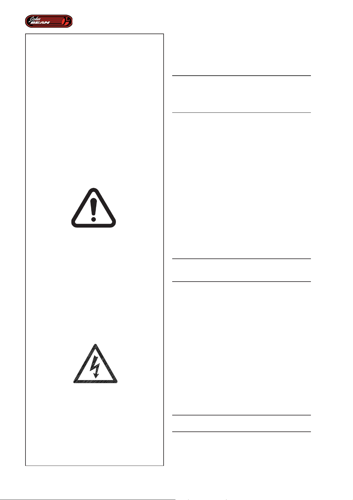
INSTRUCTION: Safety Label
CE PICTOGRAMS
P/N: EAL0413G13A
Meanings
WARNING:
MAKE SURE THAT THE SAFETY SIGNS ARE
ALWAYS CLEARLY VISIBILE IN THE POSITIONS
INDICATED BY THE MANUFACTURER (SEE
FIGURE AT THE SIDE).
For any reset, use the Part Number (P/N) listed in
this charter.
EAL0413G13A
General Danger. Take the necessary precautions.
· The areas marked with this symbol indicate the
presence of a potentional ranger to the operator.
· This plate is normally found with a second
pictogram, which represents the type of risk in
greater detail. The operator must know the meaning
of every pictogram found on the machine.
· When this symbol is found without other plate, it
notifies the operator of a general risk, refer to the
User Manual for the warnings.
· Do not operate the machine without knowiong the
meaning of the pictogram found in the area
concerned.
· Do not allow unauthorised people approach the
machine.
P/N: 8-23562A
IN ORDER TO USE THE MACHINE THE OPERATOR
MUST KNOW THE MEANING OF ALL THE
PICTOGRAMS FOUND ON THE MACHINE.
8-23562A
Electrical risk. Electric shock hazard.
• •
• Do not operate equipment with a damaged power cord
• •
or if the equipment has been dropped or damaged,
until it has been examined by a qualified service
person.
• •
• If an extension cord is necessary, a cord with a current
• •
rating equal to or greater than that of the equipment
should be used. Cords rated for less current than
the equipment can overheat.
• •
• Unplug equipment from electrical power outlet when
• •
not in use. Never use the cord to pull the plug from
the outlet. Grasp plug and pull to disconnect.
• •
• Do not expose the equipment to rain. Do not use on
• •
wet surfaces.
• •
• Plug unit into correct power supply socket.
• •
• •
• Do not remove or bypass grounding wire.
• •
CONTACT WITH HIGH VOLTAGES CAN CAUSE
DEATH OR SERIOUS INJURY.
IMPORTANT!! SAVE THESE
INSTRUCTIONS
6
Operator’s Manual
QUADRIGA 1000/BB
Page 7

Sécurité
Sicherheits
INSTRUCTIONS : Interprétation
des consignes de sécurité
ATTENTION:
FAIRE EN SORTE QUE LES SIGNAUX DE
SECURITE SOIENT TOUJOURS BIEN VISIBLES
AUX EMPLACEMENTS PREVUS PAR LE
CONSTRUCTEUR (VOIR FIGURE CI-CONTRE).
Pour en commander de neufs, utiliser le numéro de
pièce (P/N) reporté dans ce chapitre.
EAL0413G13A
Danger. Indique l’existence d’un danger et invite à la
prudence.
• Les zones contremarquées par ce symbole
indiquent à l’opérateur la présence d’un danger
potentiel.
• Ce signal est généralement accompagné d’un
second pictogramme, qui symbolise plus en détail
la catégorie de risque. L’opérateur doit connaître la
signification de tous les pictogrammes présents sur
la machine.
• Si seul ce symbole est présent, sans autres signaux,
il indique le risque d’un danger non moins précisé,
voir le Manuel d’utilisation, pour les mesures à
prendre.
• Ne pas mettre en marche sans avoir bien compris le
sens du pictogramme situé dans la zone intéressée.
• Interdire l’accès à toute personne étrangère au
service.
POUR UTILISER L’APPAREIL, L’OPERATEUR DOIT
PARFAITEMENT CONNAITRE LE SENS DE
TOUS LES PICTOGRAMMES APPOSES.
8-23562A
Risque électrique. Danger d’électrocution.
••
• Ne pas démarrer l’appareil si le câble d’alimentation
••
est endommagé ou après une chute ou en présence
de dommages, tant qu’il n’a pas été examiné par une
personne qualifiée du SAV.
••
• Si une rallonge est nécessaire, utiliser un câble ayant
••
un débit de courant égal ou supérieur au courant utilisé
pour l’appareil. Un câble de débit inférieur pourrait
surchauffer.
••
• Quand il n’est pas utilisé, toujours débrancher
••
l’appareil du coffret électrique. Ne jamais saisir le câble
pour extraire la fiche du coffret. Saisir la fiche
électrique et tirer pour débrancher.
••
• Ne pas exposer l’appareil à la pluie. Ne pas utiliser sur
••
des surfaces humides.
••
• Brancher l’unité à la bonne prise d’alimentation.
••
••
• Ne pas retirer ni désactiver le câble de terre.
••
ANLEITUNG: Bedeutung der
Sicherheitshinweise
ACHTUNG:SORGEN SIE DAFÜR, DASS DIE
SICHERHEITSHINWEISE IMMER GUT SICHTBAR
SIND UND SICH AN DEN VOM HERSTELLER
FESTGELEGTEN STELLEN BEFINDEN (SIEHE
NEBENSTEHENDE ABBILDUNG).
Falls sie ausgewechselt werden müssen, verwenden
Sie die Ersatzteilnummer (P/N), die in diesem Kapitel
angegeben ist.
EAL0413G13A
Allgemeine Gefahr. Aufmerksam sein und die nötigen
Vorsichtsmaßnahmen anwenden.
• Dieses Symbol zeigt dem Bediener an, dass die
damit gekennzeichneten Bereiche eine potenzielle
Gefahr bergen.
• Dieses Schild begleitet normalerweise ein zweites
Bildzeichen, das die Art der Gefahr genauer angibt.
Der Bediener ist dazu verpflichtet, die Bedeutung
aller Piktogramme an der Maschine zu kennen.
• Wenn dieses Symbol ohne weitere Schilder
vorhanden ist, muss man von einer allgemeinen
Gefahr ausgehen. Lesen Sie dazu bitte in den
Warnhinweisen in der Betriebsanleitung nach.
• Es dürfen keine Aktivitäten vorgenommen werden,
ohne zuvor die Bedeutung des Bildzeichens in dem
betreffenden Bereich zu kennen.
• Betriebsfremden Personen darf nicht erlaubt
werden, sich zu nähern.
DIE VERWENDUNG DES GERÄTS SETZT
VORAUS, DASS DIE BEDEUTUNG ALLER
ANGEBRACHTEN BILDZEICHEN BEKANNT IST.
8-23562A
Stromgefahr. Gefahr von Stromschlägen.
••
• Starten Sie die Maschine nicht, wenn das
••
Stromzufuhrkabel beschädigt ist, oder, falls die
Maschine beschädigt ist, bis sie von einem
fachkundigen Kundendiensttechniker geprüft wurde.
••
• Falls eine Verlängerung nötig sein sollte, verwenden
••
Sie ein Kabel, das eine gleiche oder höhere Kapazität
hat als das, was für die Maschine verwendet wird. Ein
Kabel mit geringerer Kapazität könnte sich überhitzen.
••
• Wenn die Maschine nicht verwendet wird, muss sie
••
immer vom Stromnetz getrennt werden. Ziehen Sie nie
am Kabel, um den Stecker aus der Steckdose zu
ziehen. Nehmen Sie den Stecker in die Hand und ziehen
Sie daran, um die Maschine vom Stromnetz zu trennen.
••
• Setzten Sie die Maschine keinem Regen aus.
••
Verwenden Sie sie nicht auf feuchten Flächen.
••
• Schließen Sie die Maschine an die richtige Stromdose an.
••
••
• Das Erdungskabel darf nicht entfernt oder abgeklemmt
••
werden.
LE CONTACT AVEC DES HAUTES TENSIONS PEUT
PROVOQUER LA MORT OU DE GRAVES LÉSIONS
IMPORTANT!! CONSERVER LES
PRÉSENTES INSTRUCTIONS
Manuel d’Utilisation
DER KONTAKT MIT HOCHSPANNUNG KANN ZU
SCHWEREN VERLETZUNGEN ODER ZUM TOD FÜHREN.
WICHTIG!! DIESE ANLEITUNG IST
AUFZUBEWAHREN
Betriebsanleitung
QUADRIGA 1000/BBQUADRIGA 1000/BB
7
Page 8
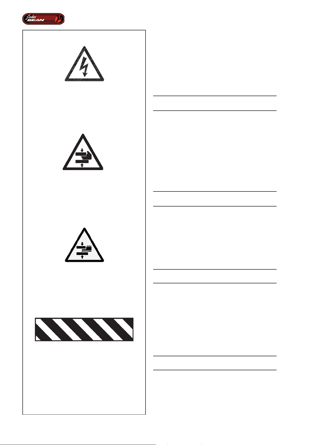
P/N: 8-23562A
P/N: EAL0383G02A
Safety
8-23562A
Risk of electrical shock. High voltages are present within
the unit.
• •
• There are no user serviceable items within the unit.
• •
• •
• Service on the unit must be performed by qualified
• •
personnel.
• •
• Do not open any part of the unit other than noted and
• •
allowed areas.
• •
• Turn power switch off and unplug the unit before
• •
servicing.
CONTACT WITH HIGH VOLTAGES CAN CAUSE
DEATH OR SERIOUS INJURY.
EAL0383G02A
Danger of crushing (upper limbs).
• •
• Become familiar with all controls before proceeding
• •
with operation.
• •
• Keep hands at a safe distance from all parts, which
• •
have a plate affixed next to them, when in operation.
••
• If necessary apply air to breaker in short bursts to
••
control better control.
••
• Keep away from the mount/dismount tool when it is
••
in use
• •
• Do not allow unauthorized people in the work area.
• •
P/N: EAL0408G71A
P/N: EAM0066G38A
CONTACT WITH MOVING PARTS COULD CAUSE
INJURY.
EAL0408G71A
Danger of crushing (lower limbs).
••
• Pay attention when the lifter is functioning and when
••
using all parts which have a plate affixed next to
them.
••
• Keep lower limbs at a safe distance.
••
• •
• Do not let unauthorized people in the work area.
• •
CONTACT WITH MOVING PARTS COULD CAUSE
INJURY.
EAM0066G38A
Danger moving parts.
Black and yellow striped tape.
••
• The tape indicates the presence of moving parts.
••
••
• These parts can be potentially dangerous.
••
••
• Pay attention when activating parts marked with this
••
type of warning sign.
• •
• Keep at a safe distance when they are moving.
• •
CONTACT WITH MOVING PARTS COULD CAUSE
INJURY.
IMPORTANT!! SAVE THESE
INSTRUCTIONS
8
Operator’s Manual
QUADRIGA 1000/BB
Page 9

Sécurité
Sicherheits
8-23562A
Risque électrique. De s hautes tensions sont présentes
à l’intérieur de l’unité.
••
• À l’intérieur de l’unité il n’existe de pas parties relevant
••
de la compétence de l’opérateur.
••
• Les interventions d’assistance sur l’unité doivent être
••
effectuées par un personnel qualifié.
••
• Ne pas ouvrir de parties de l’appareil autres que les
••
parties connues ou autorisées.
••
• Éteindre l’interrupteur et débrancher l’unité avant toute
••
intervention de service.
LE CONTACT AVEC DES HAUTES TENSIONS PEUT
PROVOQUER DE GRAVES LÉSIONS OU LA MORT
EAL0383G02A
Danger d'écrasement (membres supérieurs).
••
• Se familiariser avec toutes les commandes avant toute
••
utilisation.
••
• Garder les mains à distance de tous les organes à
••
proximité desquels ce signal est apposé.
••
•
Si nécessaire, activer le dét alonneur par à-coups pour
••
mieux en contrôler le fonctionnement
••
• Rester à distance de l’outil de démontage/montage
••
pendant son fonctionnement.
••
• Interdire aux personnes étrangères au service de
••
s’approcher du système
LE CONTACT AVEC DES PARTIES EN MOUVEMENT
PEUT PROVOQUER DES ACCIDENTS.
8-23562A
Stromgefahr. Hochspannung innerhalb der Einheit.
••
• In der Maschine befinden sich keine Teile, die vom
••
Bediener betätigt oder gewartet werden müssten.
••
• Kundendienst an der Maschine darf nur von
••
Fachpersonal durchgeführt werden.
••
• Öffnen Sie keine Teile der Maschine, wenn dies nicht
••
ausdrücklich angegeben wird.
••
• Schalten Sie den Netzschalter aus und trennen Sie
••
die Maschine vom Netz, bevor Sie Kundendienst
vornehmen lassen.
DER KONTAKT MIT HOCHSPANNUNG KANN ZU
SCHWEREN VERLETZUNGEN ODER ZUM TOD FÜHREN.
EAL0383G02A
Quetschgefahr (obere Gliedmaßen).
••
• Machen Sie sich vor der Arbeit mit allen
••
Bedienelementen vertraut.
••
• Halten Sie die Hände während des Betriebs in
••
sicherem Abstand von sämtlichen Elementen, in
deren Nähe das Schild angebracht ist.
••
• Falls nötig, aktivieren Sie den Montagearm im
••
Tippbetrieb, um seine Aktivität besser kontrollieren
zu können.
••
• Halten Sie sich vom Montage-/Demontagewerkzeug
••
fern, wenn es in Betrieb ist.
••
• Lassen Sie nie betriebsfremde Personen in die Nähe.
••
DIE BERÜHRUNG BEWEGLICHER TEILE KANN ZU
UNFÄLLEN FÜHREN.
EAL0408G71A
Danger d’écrasement (membres inférieurs).
••
• Prêter attention pendant le fonctionnement de
••
l’élévateur et dans l’utilisation de tous les organes
à proximité desquels ce signal est apposé.
••
• Se maintenir à distance, spécialement les membres
••
inférieurs.
••
• Interdire l’accès à toute personne étrangère aux
••
service.
LE CONTACT AVEC DES ORGANES MOBILES
PEUT PROVOQUER DES ACCIDENTS.
EAM0066G38A
Danger organes en mouvement.
Ruban noir à barres jaunes obliques.
••
• Ce ruban indique la présence d’organes mobiles.
••
••
• Ces organes sont potentiellement dangereux.
••
••
• Prêter attention au cours de l’actionnement des
••
pièces identifiées par cette signalétique.
••
• Se maintenir à une distance de sécurité des organes
••
en mouvement.
LE CONTACT AVEC DES ORGANES MOBILES
PEUT PROVOQUER DES ACCIDENTS.
EAL0408G71A
Quetschgefahr (untere Gliedmaßen).
••
• Seien Sie während des Betriebs der Hebebühne und
••
bei der Anwendung sämtlicher Elemente, in deren
Nähe das Schild angebracht ist, vorsichtig.
••
• Halten Sie die unteren Gliedmaßen im richtigen
••
Sicherheitsabstand.
••
• Lassen Sie niemals betriebsfremde Personen in die
••
Nähe.
DIE BERÜHRUNG BEWEGLICHER TEILE KANN ZU
UNFÄLLEN FÜHREN.
EAM0066G38A
Gefahr: Elemente in Bewegung.
Schwarzes Band mit gelben Schrägstreifen.
••
• Das Band weist auf bewegliche Elemente hin.
••
••
• Diese Elemente stellen eine potenzielle Gefahr dar.
••
••
• Seien Sie beim Betätigen der Teile, die durch diesen
••
Signalhinweis gekennzeichnet sind, vorsichtig.
••
• Halten Sie sich während der Bewegung im richtigen
••
Sicherheitsabstand.
DIE BERÜHRUNG BEWEGLICHER TEILE KANN ZU
UNFÄLLEN FÜHREN.
IMPORTANT!! CONSERVER LES
PRÉSENTES INSTRUCTIONS
Manuel d’Utilisation
WICHTIG!! DIESE ANLEITUNG IST
AUFZUBEWAHREN
Betriebsanleitung
QUADRIGA 1000/BBQUADRIGA 1000/BB
9
Page 10
Safety
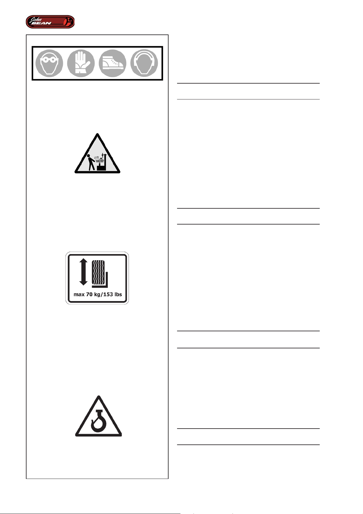
EAL0408G78A
Personal protection devices warning.
••
• All the devices listed on the plate must be used to
••
operate the equipment.
••
• Wear the devices indicated before operating the
••
equipment.
P/N: EAL0408G78A
P/N: EAL0408G77A
P/N: EAL0413G11A
THE USE OF PERSONAL PROTECTION DEVICES
IS LAID DOWN BY THE LAW.
EAL0408G77A
Risk of flying fragments during beading.
••
• The beading operation with the GT device can
••
result in flying objects and loud noise levels. We
therefore recommend the use of protection
equipment for eyes and ears.
••
• When using compressed air for the beading
••
operation there is the risk of the tire exploding.
••
• Avoid excessive pressure. Do not exceed the
••
maximum pressure indicated on the tire.
••
• The risk of explosion is also dependant on the
••
conditions of the tire. Check the tire before
inflating it.
EXPLODING TIRES CAN CAUSE SERIOUS INJURY
OR EVEN DEATH.
EAL0413G11A
Wheel lifter maximum carrying capacity.
The tyre weight must be known.
••
• The plate indicates the wheel lifter carrying
••
capacity.
••
• The mechanical parts of the wheel lifter can be
••
compromised by excessive loads.
••
• For particularly heavy tires, we recommend
••
identifying the exact weight, with a suitable
instrument, before loading on the tyre changer.
Do not use the wheel lifter if the weight exceeds
the maximum weight allowed.
••
• Maintain a safe distance when in movement.
••
10
P/N: EAL0413G12A
COMPLY WITH THE CARRYING CAPACITY OF THE
WHEEL LIFTER .
EAL0413G12A
Indications on the hooking point for lifting and moving
the tyre changer.
••
• The plate indicates where to secure the tyre
••
changer in order to lift it.
••
• Use lifting devices with an adequate carrying
••
capacity in relation to the weight of the tyre
changer.
••
• Maintain a safe distance when in movement.
••
FOLLOW THE INDICATIONS SUPPLIED FOR
MOVING THE EQUIPMENT.
IMPORTANT!! SAVE THESE
INSTRUCTIONS
Operator’s Manual
QUADRIGA 1000/BB
Page 11

Sécurité
Sicherheits
EAL0408G78A
Signalisation des équipements de protection
individuelle.
••
• Tous les équipements figurant sur les signaux sont
••
obligatoires quand on utilise la machine.
••
• Porter les équipements avant d’utiliser la machine.
••
LE PORT DES EQUIPEMENTS DE PROTECTION
INDIVIDUELLE EST IMPOSE PAR LA LOI.
EAL0408G77A
Risque de projection de fragments en phase
d’enjantage talon.
••
• L’opération d’enjantage t alon à l’aide du dispositif
••
GT peut également provoquer la projection d’objets
et du bruit. Il est donc recommandé d’utiliser les
équipements de protection appropriés pour les yeux
et les oreilles.
••
•
Si on utilise de l’air comprimé pour enjanter le
••
talon, il subsiste le danger d’explosion du pneu.
••
• Eviter les surpressions. Ne pas dépasser la pression
••
maximale indiquée sur le pneu.
••
• Le risque d’explosion dépend aussi des bonnes
••
conditions générales du pneu. Contrôler le pneu
avant d’envoyer l’air comprimé.
L’EXPLOSION D’UN PNEU PEUT PROVOQUER UN
ACCIDENT GRAVE VOIRE MORTELLES.
EAL0408G78A
Hinweis auf die Persönliche Schutzausrüstung.
••
• Für die Anwendung der Einrichtung ist die gesamte
••
Ausrüstung, die auf dem Schild angegeben ist,
vorgeschrieben.
••
• Legen Sie die vorgeschriebene Ausrüstung an,
••
bevor Sie mit der Einrichtung arbeiten.
DIE VERWENDUNG DER PERSÖNLICHEN
SCHUTZAUSRÜSTUNG IST GESETZLICH
VORGESCHRIEBEN.
EAL0408G77A
Gefahr des plötzlichen Austritts von kleinen Teilchen
während des Wulsteindrückens.
••
• Das Eindrücken der Wülste mit der GT-Vorrichtung
••
kann starken Lärm erzeugen und dazu führen, dass
Objekte herausgeschleudert werden. Es wird daher
daran erinnert, die entsprechende Schutzausrüstung
für Augen und Gehör anzuwenden.
••
•
Durch die Verwendung von Druckluft beim
••
Wulsteindrücken besteht die Gefahr, dass der
Reifen explodiert.
••
• Vermeiden Sie
••
den maximalen Druck, der auf dem Reifen
angegeben ist.
••
• Die Gefahr einer Explosion hängt auch mit dem
••
Gesamtzustand des Reifens zusammen. Überprüfen
Sie den Reifen
Überdruck. Überschreiten Sie nicht
, bevor sie Luft einlassen.
EAL0413G11A
Indication de la capacité de charge maximale de
l’élévateur.
Il est nécessaire de connaître le poids de la roue.
••
• La plaquette reporte la capacité de charge de
••
l’élévateur.
••
• Si la charge dépasse la limite préconisée, les
••
organes mécaniques de l’élévateur pourraient
s’abîmer.
••
• Si les roues sont particulièrement lourdes, il est
••
conseillé de connaître exactement leur poids, en les
pesant, avant de procéder au chargement sur le
démonte-pneus. Ne pas utiliser l’élévateur si le poids
est supérieur au poids maximum admissible.
••
• Se maintenir à une distance de sécurité quand
••
l’élévateur est en marche.
RESPECTER LA CAPACITE DE CHARGEMENT DE
L’ELEVATEUR
EAL0413G12A
Indication du point de préhension pour l'élévation et
le transport du démonte-pneus.
••
• La plaquette indique le point de fixation des
••
accessoires de levage du démonte-pneus.
••
• Utiliser des accessoires correctement dimensionnés
••
en fonction du poids du démonte-pneus.
••
• Se maintenir à une distance de sécurité quand
••
l’élévateur est en marche.
DIE EXPLOSION EINES REIFENS KANN ZU
SCHWEREN ODER SOGAR TÖDLICHEN UNFÄLLEN
FÜHREN.
EAL0413G11A
Angabe der maximalen Ladekapazität des Radhebers.
Das Gewicht des Rads muss bekannt sein.
· Auf dem Schild steht die T ragfähigkeit des Radhebers.
· Die mechanischen Organe des Radhebers könnten
durch höhere Belastungen beeinträchtigt werden.
· Bei besonders schweren Rädern wird empfohlen, das
Gewicht mit einem geeigneten Instrument exakt
festzustellen, bevor man sie auf das Reifenmontiergerät
lädt. Verwenden Sie den Radheber nicht, wenn das
Gewicht über dem zulässigen Höchstwert liegt.
· Halten Sie den Sicherheitsabstand ein, wenn das
Gerät in Bewegung ist.
DIE LADEKAPAZITÄT DES RADHEBERS IST ZU
BEACHTEN.
EAL0413G12A
Angabe der Kupplungsstelle zum Heben und zum
Umsetzen des Reifenmontiergeräts.
· Auf dem Schild steht die Stelle zur Befestigung der
Hilfsvorrichtungen zum Anheben des Reifenmontiergeräts.
· Verwenden Sie Hilfsvorrichtungen der richtigen
Größe für das Gewicht des Reifenmontiergeräts.
· Halten Sie den Sicherheitsabstand ein, wenn das
Gerät in Bewegung ist.
RESPECTER LES INDICATIONS FOURNIES POUR
LA MANUTENTION DE L’EQUIPEMENT.
IMPORTANT!! CONSERVER LES
PRÉSENTES INSTRUCTIONS
Manuel d’Utilisation
BEACHTEN SIE DIE ANGABEN FÜR DAS
UMSETZEN DES GERÄTS.
WICHTIG!! DIESE ANLEITUNG IST
AUFZUBEWAHREN
Betriebsanleitung
QUADRIGA 1000/BBQUADRIGA 1000/BB
11
Page 12
Safety
1.0 Safety.
The safety precautions must be completely understood
and observed by every operator.
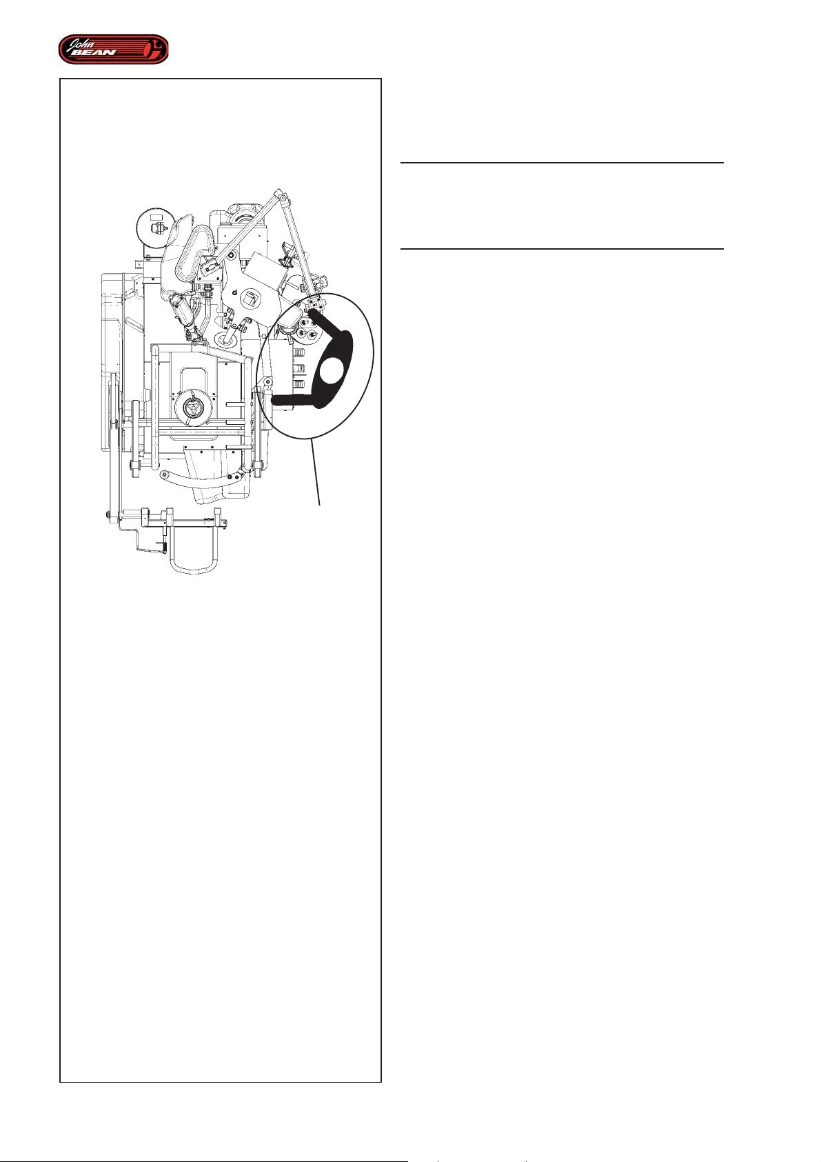
WARNING: THIS MACHINE HAS A SINGLE
OPERATING STATION (A). THE OPERATOR IS
RESPONSIBLE FOR RESTRICTING ACCESS TO THE
WORK AREA AND FOR ANY CONSEQUENCE
ARISING FROM USING THE EQUIPMENT
THE USE OF THIS DEVICE IS ALLOWED ONLY TO
PERSONNEL DUL Y TRAINED BY AN AUTHORIZED
DEALER.
ANY T AMPERING WITH OR MODIFICA TION OF THIS
DEVICE OR ITS PARTS OR COMPONENTS NOT
PREVIOUSLY AUTHORIZED BY THE
MANUFACTURER SHALL EXONERATE THE
MANUFACTURER FROM ANY LIABILITY
RESULTING FROM OR RELATED TO THE ABOVEMENTIONED T AMPERINGS.
A
REMOVING OR BYP ASSING SAFETY DEVICES OR
WARNING LABELS OF THE MACHINE IS A
VIOLATION OF THE SAFETY REGULA TIONS.
THE USE OF THIS DEVICE IS ALLOWED ONLY IN
LOCATIONS WITH NO EXPLOSION OR FIRE
HAZARD.
INSTALLA TION SHALL BE CARRIED OUT ONL Y BY
QUALIFIED PERSONNEL AND WITHIN THE SCOPE
OF THE INSTRUCTIONS PROVIDED IN THIS
MANUAL.
THIS DEVICE IS DESIGNED TO ACCEPT ORIGINAL
SP ARE P ARTS AND ACCESSORIES ONLY.
CHECK FOR POSSIBLE DANGEROUS CONDITIONS
DURING THE OPERATION OF THE MACHINE. IN
SUCH A CASE ST OP THE MACHINE IMMEDIA TEL Y .
IN THE EVENT OF MALFUNCTIONS, STOP THE
MACHINE AND CALL THE AUTHORIZED
DISTRIBUTOR FOR TECHNICAL ASSIST ANCE.
DURING USE AND MAINTENANCE OF THE MACHINE
IT IS MANDATORY TO COMPLY WITH ALL
ACCIDENT PREVENTION LAWS AND
REGULA TIONS.
12
Operator’s Manual
QUADRIGA 1000/BB
Page 13

Sécurité
Sicherheit
1.0 Sécurité.
Les consignes de sécurité doivent être assimilées et
observées par tout opérateur.
ATTENTION : CETTE MACHINE A UN SEUL POSTE
OPERATIONNEL (A). L’OPERATEUR A LA
RESPONSABILITE DE LIMITER L’ACCES A LA ZONE
DE TRAVAIL ET DES CONSEQUENCES LIEES A
L’EMPLOI DE L’EQUIPEMENT.
L’UTILISATION DE L’APPAREIL N’EST PERMISE
QU’AU PERSONNEL OPPORTUNÉMENT FORMÉ
P AR LE DISTRIBUTEUR AGRÉÉ.
TOUTE MANIPULATION VOLONTAIRE OU
MODIFICATION QUELLE QU’ELLE SOIT DE
L’APPAREIL OU DE SES COMPOSANT, NON
PRÉALABLEMENT AUTORISÉE PAR LE
CONSTRUCTEUR, DÉGAGE CELUI-CI DES
DOMMAGES CAUSÉS PAR OU RAPPORTABLES
AUX ACTIONS SUSMENTIONNÉES.
LE RETRAIT OU L’AL TÉRA TION DES DISPOSITIFS
DE SÉCURITÉ OU DE MISES EN GARDE INST ALLÉS
SUR LA MACHINE ENTRAÎNE UNE VIOLA TION DES
RÈGLES SUR LA SÉCURITÉ.
L’UTILISA TION DE L ’APP AREIL N’EST AUTORISÉE
QU’EN LIEUX SANS DANGER D’EXPLOSION OU
D’INCENDIE.
L’INST ALLA TION DOIT ÊTRE EFFECTUÉE P AR UN
PERSONNEL QUALIFIÉ DANS LE TOT AL RESPECT
DES INSTRUCTIONS INDIQUÉES DANS CE
MANUEL.
1.0 Sicherheit.
Die Sicherheitsmaßnahmen müssen von allen Bedienern
vollständig verstanden und eingehalten werden.
ACHTUNG: DIESE MASCHINE HAT NUR EINEN
EINZIGEN BEDIENERPLATZ (A). DER BEDIENER IST
FÜR DIE BEGRENZUNGEN DES ARBEITSBEREICHS
UND FÜR ALLE KONSEQUENZEN
VERANTWORTLICH, DIE DURCH DIE
VERWENDUNG DES GERÄTS ENTSTEHEN.
DAS GERÄT DARF NUR VON PERSONAL BEDIENT
WERDEN, DAS DURCH DEN VERTRAGSHÄNDLER
ENTSPRECHEND DAFÜR GESCHUL T WURDE.
JEDE ART VON EINGRIFF ODER VERÄNDERUNG
DES GERÄTS ODER SEINER BEST ANDTEILE, DIE
OHNE VORHERIGE ZUSTIMMUNG DES
HERSTELLERS VORGENOMMEN WURDE,
ENTBINDEN DIESEN VON DER HAFTUNG FÜR
SCHÄDEN, DIE AUF BESAGTE HANDLUNGEN
ZURÜCKZUFÜHREN SIND.
DIE ENTFERNUNG ODER VERÄNDERUNG VON
SICHERHEITSVORRICHTUNGEN ODER
WARNHINWEISEN AM GERÄT STELLT EINE
VERLETZUNG DER SICHERHEITSVORSCHRIFTEN DAR.
DAS GERÄT DARF NUR AN ORTEN BETRIEBEN
WERDEN, AN DENEN KEINE EXPLOSIONS- ODER
BRANDGEFAHR BESTEHT .
DIE INST ALLATION IST VON F ACHPERSONAL UNTER
STRENGER EINHALTUNG DER HIER AUFGEFÜHRTEN
ANWEISUNGEN DURCHZUFÜHREN.
CETTE MACHINE A ÉTÉ CONÇUE POUR NE
RECEVOIR QUE DES ACCESSOIRES OU DES
PIÈCES DE RECHANGE D’ORIGINE.
CONTRÔLER QUE, PENDANT LES MANŒUVRES,
AUCUNE CONDITION DE DANGER NE SE VERIFIE.
LE CAS ÉCHÉANT , ARRÊTER IMMÉDIA TEMENT LA
MACHINE.EN CAS DE CONSTATATION
D’IRRÉGULARITÉS DE FONCTIONNEMENT,
SUSPENDRE LES OPÉRA TIONS ET CONTACTER LE
SERVICE ASSIST ANCE DU DISTRIBUTEUR AGRÉÉ.
PENDANT L’UTILISA TION ET L ’ENTRETIEN DE LA
MACHINE IL EST IMPÉRATIF DE RESPECTER
TOUTES LES LOIS ET LES RÈGLES POUR LA
PRÉVENTION DES ACCIDENTS.
FÜR DIESE MASCHINE DÜRFEN NUR ORIGINALZUBEHÖR UND –ERSATZTEILE VER WENDET WERDEN.
SICHERSTELLEN, DASS SICH WÄHREND DER
BETRIEBSVORGÄNGE KEINE GEFAHRENSITUA TIONEN
ERGEBEN. ANSONSTEN DAS GERÄT SOFORT
ANHALTEN. WERDEN UNREGELMÄSSIGKEITEN IN DER
FUNKTIONSWEISE DES GERÄTS FESTGESTELL T , DIE
ARBEITSVORGÄNGE UNTERBRECHEN UND DEN
KUNDENDIENST DES VERTRAGSHÄNDLERS
EINSCHAL TEN.
WÄHREND BETRIEB UND WARTUNG DIESER
MASCHINE SIND UNBEDINGT ALLE GEL TENDEN
VORSCHRIFTEN ZUR UNFALLVERHÜTUNG
EINZUHALTEN.
Manuel d’Utilisation
Betriebsanleitung
QUADRIGA 1000/BBQUADRIGA 1000/BB
13
Page 14

Safety
THE ELECTRICAL SYSTEM MUST HA VE AN EARTH
CABLE AMD THE MACHINE EARTH CABLE
(YELLOW/GREEN) MUST BE CONNECTED TO THE
EARTH CABLE OF THE MAINS SUPPL Y
BEFORE PERFORMING ANY MAINTENANCE OR
REPAIRS THE MACHINE MUST BE DISCONNECTED
FROM THE ELECTRIC SUPPL Y .
NEVER WEAR TIES, CHAINS OR OTHER LOOSE
ARTICLES WHEN USING, MAINTAINING OR
REPAIRING THE MACHINE. LONG HAIR IS ALSO
DANGEROUS AND SHOULD BE KEPT UNDER A HAT.
THE USER MUST WEAR PROPER SAFETY A TTIRE
I.E.: GLOVES, SAFETY SHOES AND GLASSES.
MAINTAIN ALL ELECTRIC CABLES IN GOOD
REP AIR.
KEEP SAFETY DEVICES IN PLACE AND IN
WORKING ORDER.
KEEP WORKING AREA TIDY . CLUTTERED AREAS
INVITE ACCIDENTS.
PREVENT DANGEROUS SITUATIONS. DO NOT USE
PNEUMA TIC OR ELECTRICAL EQUIPMENT IN DAMP
OR WET LOCATIONS, OR EXPOSE THEM T O RAIN.
KEEP THE WORK AREA WELL LIT.
THE WHEEL LIFTER MUST NOT BE USED FOR
OTHER REASONS.
ALL WORK ON THE ELECTRICAL SYSTEM MUST
BE CARRIED OUT BY LICENSED TECHNICIANS.
ALL REPAIRS MUST BE PERFORMED BY AN
AUTHORIZED SERVICE TECHNICIAN.
14
1.1 Format of this Manual.
This manual contains text styles designed to draw the
user’s attention:
Note: Suggestion or explanation.
CAUTION: STRESSES THAT THE FOLLOWING
ACTION MAY CAUSE DAMAGE TO THE UNIT OR
OBJECTS ATTACHED TO IT.
Operator’s Manual
QUADRIGA 1000/BB
Page 15

Sécurité
Sicherheit
L’INST ALLA TION ÉLECTRIQUE DOIT ÊTRE ÉQUIPÉE
D’UN CÂBLE DE TERRE ET LE CÂBLE DE TERRE
DE LA MACHINE (JAUNE/VERT) DOIT ÊTRE
BRANCHÉ AU CÂBLE DE TERRE DE
L’INST ALLA TION DE DISTRIBUTION.
AVANT TOUTE OPÉRATION D’ENTRETIEN ET DE
RÉPARATION, LA MACHINE DOIT ÊTRE
DÉBRANCHÉE DU RÉSEAU ÉLECTRIQUE.
NE JAMAIS PORTER DE CRAVATES, DE CHAÎNES
OU OBJETS SIMILAIRES LORS DES OPÉRATIONS
D’UTILISATION, D’ENTRETIEN OU DE RÉP ARA TION
SUR LA MACHINE. LES CHEVEUX LONGS SONT
ÉGALEMENT DANGEREUX. ILS DOIVENT ÊTRE
RASSEMBLÉS SOUS UNE CASQUETTE OU AUTRE.
L’OPÉRA TEUR DOIT PORTER DES DISPOSITIFS DE
PROTECTION PERSONNELLE TELS QUE GANTS,
CHAUSSURES DE SÉCURITÉ ET LUNETTES.
LES CÂBLES ÉLECTRIQUES DOIVENT ÊTRE
CONSERVÉS EN BON ÉT A T .
LES DISPOSITIFS DE SÉCURITÉ DOIVENT RESTER
ACTIFS ET FONCTIONNER CORRECTEMENT .
LA ZONE DE TRA V AIL DOIT ÊTRE TENUE PROPRE.
LES ENDROITS DÉSORDONNÉS F A VORISENT LES
ACCIDENTS.
DIE ELEKTROANLAGE AM BETRIEBSORT MUSS
ÜBER EINE ERDUNG VERFÜGEN. DAS
ERDUNGSKABEL (GELB-GRÜN) MUSS AN DAS
GELB-GRÜNE ERDUNGSKABEL DER
STROMANLAGE ANGESCHLOSSEN WERDEN.
VOR ALLEN REPARATUREN UND
WARTUNGSARBEITEN MUSS DIE STROMZUFUHR
DER MASCHINE ABGESCHALTET WERDEN UND
GEGEN WIEDEREINSCHAL TEN GESICHERT WERDEN.
WÄHREND DER BETRIEBS-, WARTUNGS- UND
REPARATURARBEITEN AN DER MASCHINE
DÜRFEN KEINE KRAWATTEN, KETTEN ODER
ANDERE LOSE ACCESSOIRES GETRAGEN
WERDEN. AUCH LANGE HAARE SIND GEFÄHRLICH
UND DESHALB ENTSPRECHEND ZU SCHÜTZEN.
DER BEDIENER MUSS DIE ANGEMESSENE
PERSÖNLICHE SCHUTZAUSRÜSTUNG WIE
HANDSCHUHE, SICHERHEITSSCHUHE UND
SCHUTZBRILLE TRAGEN.
ELEKTRISCHE KABEL MÜSSEN IN GUTEM
ZUST AND GEHALTEN WERDEN.
DIE SICHERHEITSVORRICHTUNGEN MÜSSEN
IMMER AKTIV UND FUNKTIONSBEREIT GEHAL TEN
WERDEN.
DAS ARBEITSUMFELD IST SAUBER ZU HAL TEN.
UNORDNUNG BEGÜNSTIGT UNFÄLLE.
ÉVITER LES SITUA TIONS DANGEREUSES. NE PAS
UTILISER D’OUTILS PNEUMATIQUES OU
ÉLECTRIQUES DANS DES LIEUX HUMIDES ET
GLISSANTS NI LES EXPOSER AUX INTEMPÉRIES.
LA ZONE DE TRA V AIL DOIT ÊTRE BIEN ÉCLAIRÉE.
L’ELEV A TEUR ROUES NE DOIT P AS ETRE UTILISE
DANS UN BUT DIFFERENT .
TOUTES LES INTERVENTIONS SUR L’INSTALLATION
ÉLECTRIQUE DOIVENT ÊTRE RÉALISÉES PAR UN
PERSONNEL PROFESSIONNELLEMENT QUALIFIÉ.
TOUTES LE RÉPARATIONS DOIVENT ÊTRE
EFFECTUÉES PAR DES TECHNICIENS AGRÉÉS.
1.1 Typographie
Ce manuel contient des styles de texte qui demandent
une attention particulière:
Remarque: Suggestion ou explication.
GEFAHRENSITUA TIONEN UNBEDINGT VERMEIDEN.
PNEUMATISCHE ODER ELEKTRISCHE
WERKZEUGE NICHT IN FEUCHTEN ODER
RUTSCHIGEN RÄUMEN VERWENDEN UND KEINEN
NEGATIVEN WETTEREINFLÜSSEN AUSSETZEN.
FÜR AUSREICHENDE BELEUCHTUNG AM
BETRIEBSORT SORGEN.
DER RADHEBER DARF FÜR KEINE ANDEREN
ZWECKE VERWENDET WERDEN.
ALLE ARBEITEN AN DER ELEKTROANLAGE
DÜRFEN NUR VON ELEKTROFACHRÄFTEN
VORGENOMMEN WERDEN.
ALLE REPARATUREN MÜSSEN VON ZUGELASSENEN
TECHNIKERN DURCHGEFÜHRT WERDEN
1.1 Typographie.
Dieses Handbuch enthält Schriftweisen, die zu
besonderer Vorsicht auffordern:
Anmerkung: Vorschlag oder Erklärung
ATTENTION: INDIQUE QUE L’ACTION QUI SUIT
RISQUE D’ENDOMMAGER LA MACHINE OU DES
OBJETS ASSEMBLÉS A LA MACHINE.
Manuel d’Utilisation
VORSICHT: WEIST DARAUF HIN, DASS DIE
FOLGENDE MASSNAHME ZU SCHÄDEN AM GERÄT
ODER DARAN BEFESTIGTEN TEILEN FÜHREN KANN.
Betriebsanleitung
QUADRIGA 1000/BBQUADRIGA 1000/BB
15
Page 16
Safety
WARNING: STRESSES THAT THE FOLLOWING
ACTION MAY CAUSE (SEVERE) INJURY TO THE
OPERATOR OR OTHERS.
• Bulleted list:
• Indicates that the action must be executed by the
operator before being able to go to the next step in the
sequence.
0.0-1
A dotted line around the number of the figure indicates
that this is a duplicate from a previous section.
4
6
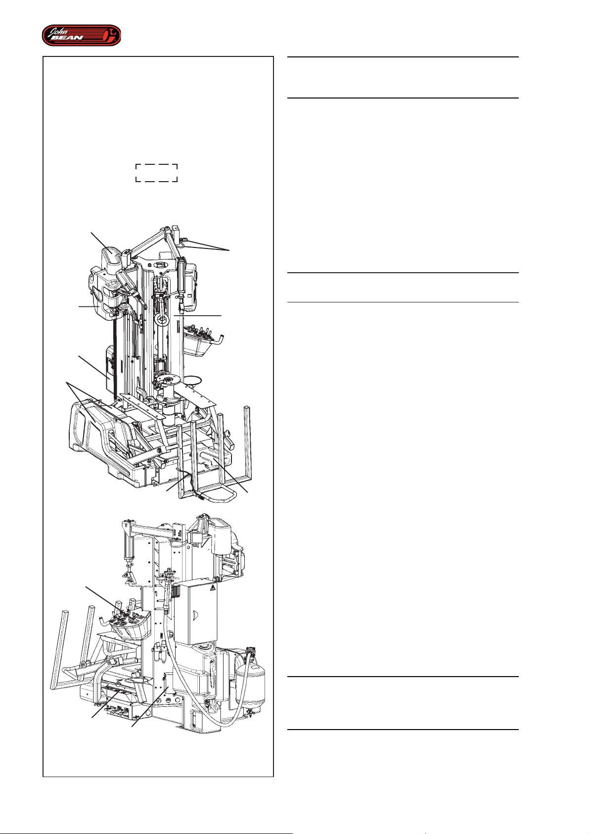
1.2 Safety Devices
WARNING: DO NOT BYPASS ANY SAFETY
FEATURES.
11
9
This machine has several protectors and devices to
prevent compression or crushing hazards.
8
1
2
3
List of safety devices:
Figura 1.2-1
1. lifter guard
2. anti-lift device
3. motor drive guard
4. upper cover
5. pedal control guard
6. control lever guard
7. power supply cut-out device
8. solenoid valve guard
9. bead breaker guard
10.beading device limiter
11.demounting tool carriage guard
16
- The rotation speed of the chuck has been limited to a
maximum of 7-14 rpm to prevent dragging or entrapping
7
5
hazards.
- Rotation of the turntable is automatically inhibited
when the main switch is off (position 0) as well as the
pre-positioned pedal control release.
WARNING: IN THE EVENT OF MALFUNCTION OR
BREAKAGE OF ONE OF THE SAFETY DEVICES,
DO NOT USE THE MACHINE AND CONTACT THE
ASSISTANCE SERVICE TO RESTART.
10
1.2-1
Operator’s Manual
QUADRIGA 1000/BB
Page 17

Sécurité
Sicherheit
A TTENTION : INDIQUE QUE L’ACTION QUI SUIT PEUT
PROVOQUER DES BLESSURES (MÊME SÉRIEUSES)
À L’OPERATEUR OU À DES TIERCES PERSONNES.
• Liste à puces:
• Indique l’action qui doit être effectuée par l’opérateur avant
de pouvoir passer à l’étape suivante de la séquence.
Les pointillés autour du numéro de la figure indiquent
qu’il s’agit d’un duplicata provenant d’un chapitre
précédent.
1.2 Dispositifs De Sécurité
A TTENTION : NE DÉSACTIVER AUCUN DISPOSITIF
DE SÉCURITÉ.
Cette machine est équipée de différentes
protections et dispositifs pour éviter les risques
d’écrasement ou de compression.
WARNUNG: WEIST DARAUF HIN, DASS DIE
FOLGENDE MASSNAHME ZU (SCHWEREN)
VERLETZUNGEN DES BEDIENERS ODER ANDERER
PERSONEN FÜHREN KANN.
• Aufzählungspunkte:
• zeigen an, dass der Bediener Maßnahmen
durchführen muss, bevor er zum nächsten Schritt
des Vorgangs übergehen kann.
Ein gestrichelter Rahmen um die Nummer der Abbildung
zeigt an, dass es sich um ein Duplikat aus einem
vorherigen Abschnitt handelt.
1.2 Sicherheitsvorrichtungen
WARNUNG: ÜBERBRÜCKEN SIE KEINE
SICHERHEITSVORRICHTUNG.
Dieses Gerät wurde mit verschiedenen
Schutzeinrichtungen und Sicherheitsvorrichtungen zur
Vermeidung von Quetsch- und Stauchgefahren
ausgestattet.
Liste des dispositifs de sécurité:
Figure 1.2-1
1. Protection élévateur
2. Dispositif anti-élévation
3. Protection transmission moteur
4. Carter supérieur
5. Protection pédales
6. Protection levier de commande
7. Dispositif de coupure alimentation électrique
8. Protection électrovalves
9. Protection détalonneur
10. Limiteur pour le dispositif d’enjantage talon
11. Protection Chariot Outils de démontage
- La vitesse de rotation du mandrin a été limitée à un
maximum de 7-14 t/min pour éviter les risques
d’entraînement ou de blocage.
- Le mouvement de rotation de l’autocentrant est
automatiquement bloqué dès que l’interrupteur général
est désenclenché (position 0) et que la pédale de la
commande correspondante est relâchée.
Liste der Sicherheitsvorrichtungen:
Abb.1.2-1
1. Schutzabdeckung der Hebebühne
2. Vorrichtung zum Sperren des Hebens
3. Schutzabdeckung des Antriebsriemens des Motors
4. Obere Abdeckung
5. Schutz der Pedale
6. Schutz des Steuerhebels
7. Vorrichtung zur Unterbrechung der Stromzufuhr
8. Schutz der Magnetventile
9. Schutz des Wulstablösers
10. Begrenzungsvorrichtung für die Wulsteindrückvorrichtung
11.Schutz des Wagens der Montagewerkzeuge
- Die Drehgeschwindigkeit des Spannfutters wurde auf
maximal 7-14 U/min begrenzt, um die Gefahr, mitgerissen
zu werden oder sich zu verfangen, zu vermeiden.
- Die Drehbewegung des Spannfutters wird automatisch
gesperrt, wenn der Hauptschalter ausgeschaltet ist
(Position 0), sowie dann, wenn das betreffende
Steuerpedal losgelassen wird.
A TTENTION : EN CAS DE PANNE OU DE RUPTURE
DE L’UN DES DISPOSITIFS DE SÉCURITÉ, NE
PAS UTILISER LA MACHINE ET CONTACTER
LE SERVICE ASSISTANCE POUR LA
RÉPARATION.
Manuel d’Utilisation
ACHTUNG: BEI EINER STÖRUNG ODER DEM
BRUCH EINER DER SICHERHEITS-VORRICHTUNGEN DIE MASCHINE NICHT WEITER
VERWENDEN, SONDERN SICH AN DEN
KUNDENDIENST WENDEN.
Betriebsanleitung
QUADRIGA 1000/BBQUADRIGA 1000/BB
17
Page 18
Safety
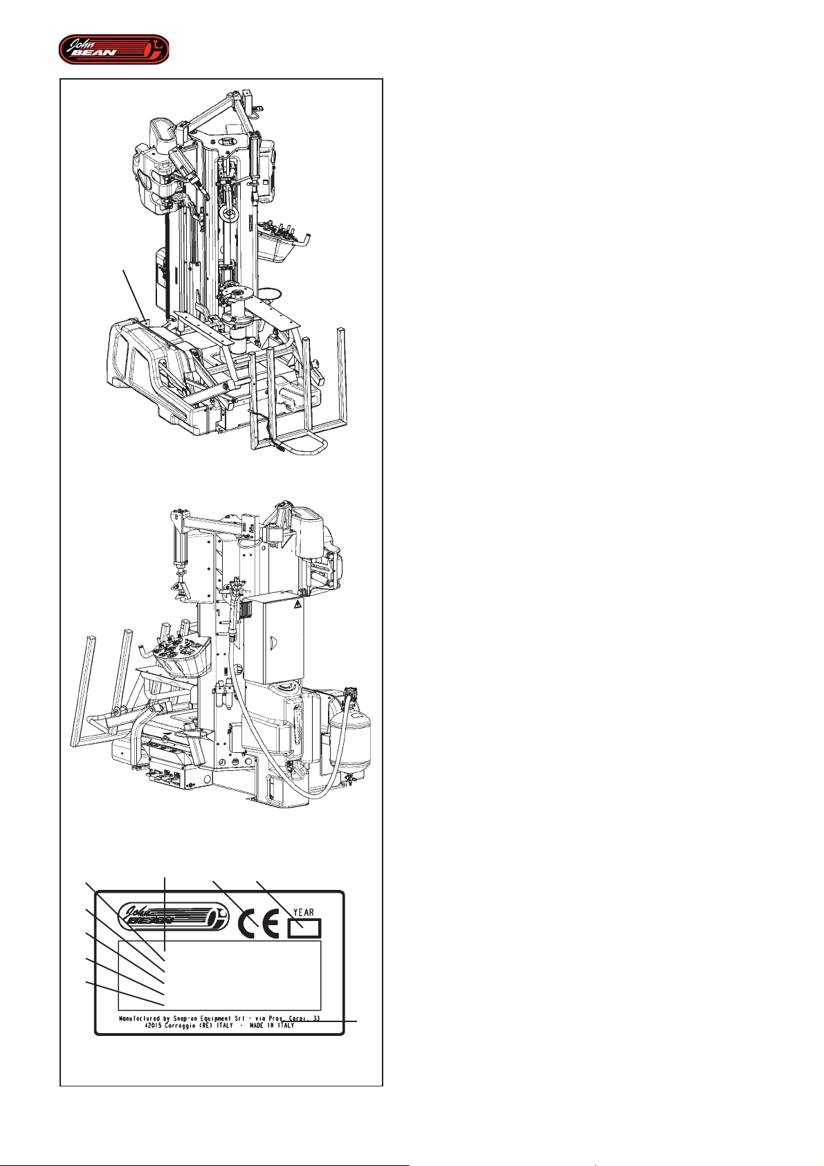
1.3 Machine models
This manual deals with machine models that share the
same structure and functionality, but that can vary in
terms of the automated equipment fitted. However, there
may be differences with regard to the power supply
and the presence/absence of the beading device for
tubeless tires.
1
1.3-1
The difference is set out below:
Figure 1.3-1
Represents the basic machine.
Figure 1.3-2
Represents the same machine as above, but it is also
equipped with a beading unit for tubeless tires.
The changes in power supply depend on the destination
country or on specific client requests.
Types of power supply:
230 Vac, 1 Ph, 50/60 Hz.
or
115 Vac, 1 Ph, 50/60 Hz.
1.3-2
d
e
b c
1.4 Identification data
An identification plate attached to the machine, in
position 1, Fig. 1.3-1, shows the following data Fig.
1.4-1:
f
g
h
i
1.4-1
a- Name and address of the manufacturer
b- Conformity marking
c- Year of manufacture
d- Model
e- Serial number
f- Weight
a
g- Electric specifications (volt, ph, Hz, kW and A)
h- Operating pressures (Air/Oil)
i- Acoustic pressure
18
Operator’s Manual
QUADRIGA 1000/BB
Page 19

Sécurité
Sicherheit
1.3 Modèles de machine
Ce manuel décrit des modèles de machine identiques
par la structure et les fonctions, mais qui peuvent être
différents suivant l'alimentation électrique et la présence
ou l'absence du dispositif d’enjantage talon pour pneus
tubeless.
Les modèles ont les différences suivantes :
La figure 1.3-1
représente la machine de base.
La figure 1.3-2
représente la même machine équipée visée supra mais
équipée en plus d'une unité d’enjantage talon pour
pneus tubeless.
1.3 Maschinenmodelle
In diesem Handbuch werden Maschinenmodelle
beschrieben, die strukturell und funktionell gleich sind,
sich aber durch die Art der Stromzufuhr unterscheiden
können, sowie dadurch, ob die Vorrichtung zum
Wulsteindrücken für schlauchlose Reifen vorhanden
oder nicht vorhanden ist.
Die Modelle unterscheiden sich folgendermaßen:
In der Abbildung 1.3-1
wird die Basismaschine.
In der Abbildung 1.3-2
wird die gleiche Maschine wie oben, aber zusätzlich
mit der Wulsteindrückvorrichtung für schlauchlose
Reifen ausgestattet gezeigt.
Les variantes d’alimentation électrique dépendent du
pays de destination ou des spécifications requises par
le client.
Types d’alimentation électrique actuellement prévus :
230 Vac, 1 Ph, 50/60 Hz.
ou
115 Vac, 1 Ph, 50/60 Hz.
1.4 Données de marquage
Appliquée au démonte-pneus, position 1, Fig. 1.3-1,
vous trouverez une plaque avec les données suivantes
Fig. 1.4-1:
a- Nom et adresse du constructeur
b- Marquage de conformité
c- Année de construction
d- Modèle
e- Numéro de série
f- Poids net
g- Caractéristiques électriques (volt, ph, Hz, kW et A)
h- Pressions d'exercice (Air / Huile)
i- Niveau de pression sonore
Die Varianten der Stromzufuhr hängen mit
Bestimmungsland der Maschine oder mit bestimmten
Anforderungen des Kunden zusammen.
Aktuell vorgesehene Arten von Stromzufuhr:
230 Vac, 1 Ph, 50/60 Hz
oder
115 Vac, 1 Ph, 50/60 Hz
1.4 Markierungsdaten
An der Reifenmontiermaschine ist an der Position 1,
Abb. 1.3-1 ein Markierungsschild angebracht, das folgende
Daten enthält Abb. 1.4-1:
a- Name und Addresse des Herstellers
b- Konformitätsmarkierung
c- Baujahr
d- Modell
e- Seriennummer
f- Nettogewicht
g- Elektrische Daten (Volt, ph, Hz, kW und A)
h- Betriebsdruckwerte (für Luft/Öl)
i- Schalldruckpegel
Manuel d’Utilisation
Betriebsanleitung
QUADRIGA 1000/BBQUADRIGA 1000/BB
19
Page 20
Specifications
2.0 Specifications
Electric-hydraulic-pneumatic tire changers for motor
vehicle, SUV and light truck Tubeless wheels.
Weight with standard accessories ...820Kg (1808 lbs)
Electric Specifications:
EU........…......….....….......……230V AC, 1Ph, 50Hz
USA.................................…....220 Vac, 1Ph, 60Hz
Chuck Motor power:.....................0.9 kW (1.2 HP)
Max. chuck torque.... ............Nm 1500 (1106lbfxft)
Chuck rotation speed........……................7-14 rpm
Capability.......….....…......…...........….........12-30"
Max. wheel diameter.......….....….1200 mm (47.2")
Max. rim width.......….......…………...432 mm (17")
Minimum rim centre hole.....…..................40 mm
Acoustic pressure........……………...…....<70 dB(A)
Fig. 2-1
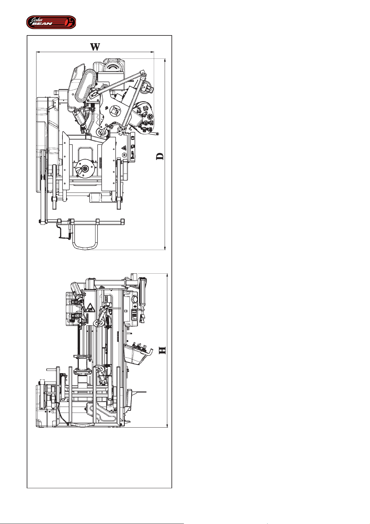
Dimensions (H x D x W), expressed in mm and inches.
Version w/wo Tubeless tires Beading device.
W min. = 1290 – 50,8"
W max. = 1350 – 53,1"
D = 2240 – 88,1"
H = 1850 – 72,8"
2.1 Conditions
During use or prolonged storage, conditions must never
be outside:
Temperature range from 0 to 50 °C
Humidity range from 10 to 90%,
without condensation
20
2-1
Operator’s Manual QUADRIGA 1000/BB
Page 21

Spécifications
Spezifikationen
2.0 Spécifications
Démonte-pneu électro-hydraulique-pneumatique pour
roues Tubeless de voitures, SUV et fourgons
Poids avec accessoires de série.820 Kg (1808 lbs)
Caractéristiques électriques:
EU........…......….....….......……230V AC, 1Ph, 50Hz
USA.................................…....220 Vac, 1Ph, 60Hz
Puissance moteur mandrin:..........…0.9 kW (1.2 HP)
Couple maximum mandrin....1500 Nm (1106 lbfxft)
Vitesse de rotation mandrin ...................7-14 rpm
Capacité.......….....…......…...........….....…...12-30"
Diamètre max. roue..........….........1200mm (47,2")
Largeur max. pneu....…...….............432 mm (17")
Minimum trou du jante.…..........................40 mm
Pression sonore........……..………..........<70 dB(A)
Fig. 2-1
Dimensions (H x P x L), exprimées en millimètres et
pouces.
2.0 Spezifikationen
Elektrohydraulisch-pneumatische Reifenmontiermaschinen
für Schlauchlosreifen von Kraftfahrzeugen, SUV und
Lieferwagen- bzw. Kleinlastwagen.
Gewicht mit Serienzubehör …....820Kg (1808 lbs)
Elektrische Daten:
EU........…......….....….......……230V AC, 1Ph, 50Hz
USA.................................…....220 Vac, 1Ph, 60Hz
Leistung des Spannfuttermotors:..0.9 kW (1.2 HP)
Antriebsdrehmoment, max... 1500 Nm (1106 lbfxft)
Drehgeschw. Spannvorrichtung............. 7-14 rpm
Fähigkeit.......….....…......…...........….....…...12-30"
Max. Raddurchmesser....……...... 1200 mm (47,2")
Max. Felgenbreite.…………….......... 432 mm (17")
Min. Zentrum Loch.....….….........................40 mm
Schalldruckpegel........………….............<70 dB(A)
Abb. 2-1
Abmessungen (H x D x B) ausgedrückt in Millimetern
und Zoll.
Version avec et sans dispositif d’enjantage talon pour
pneus Tubeless
W min. = 1290 – 50,8”
W max. = 1350 – 53,1”
D = 2240 – 88,1”
H = 1850 – 72,8”
2.1 Conditions
Lors de l’utilisation ou d’un stockage prolongé les
conditions ne doivent jamais dépasser :
Conditions de température de 0 à 50°C
Condtions d’humidité de 10 à 90%,
sans condensation
Version mit und ohne Wulsteindrückvorrichtung für
Schlauchlosreifen
W min. = 1290 – 50,8”
W max. = 1350 – 53,1”
D = 2240 – 88,1”
H = 1850 – 72,8”
2.1 Bedingungen
Während der Benutzung und der Langzeitlagerung
dürfen die folgenden Werte nicht überschritten werden.
Temperaturbereich von 0 bis 50° C
Luftfeuchtigkeitsbereich von 10 bis 90 %,
nicht kondensierend
Manuel d’Utilisation QUADRIGA 1000/BBQUADRIGA 1000/BB
Betriebsanleitung
21
Page 22
Introduction
3.0 Introduction
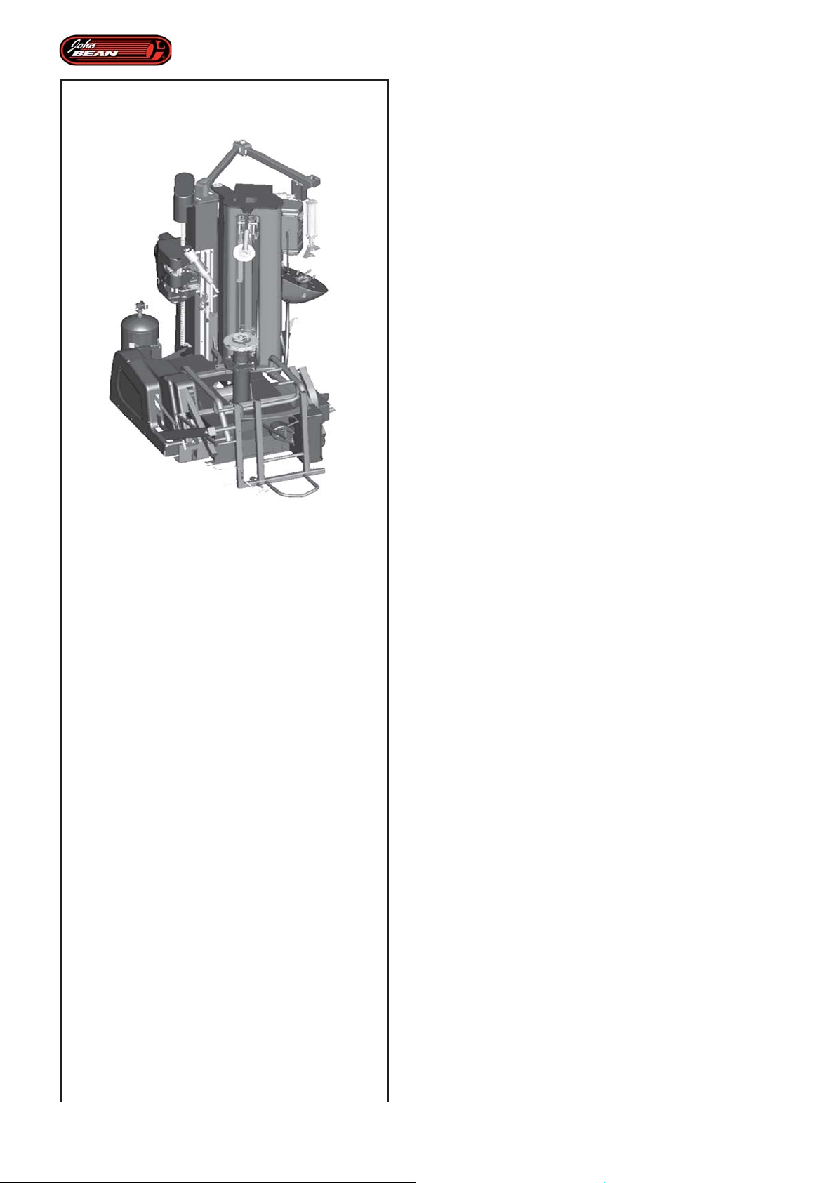
Congratulations on purchasing your Automatic Tire
Changer:
Thanks to this machine’s state-of-the-art computer
technology-based design, tire mounting and demounting
operations can now be performed automatically.
Specifically manufactured for professionals with a busy
work schedule, this machine changes tires
automatically. Following a preset operating cycle stored
in the machine’s memory, all operations are performed
in complete safety. This is possible thanks to numerous
sensors that provide the software instantly with the exact
situation of the various parts so the operator can choose
to activate or pause the operating cycle. As long as the
relevant lever is kept in the ON position, automated
parts perform the required operations. But as soon as
the lever is released, the automatic procedure is paused
and all the mobile parts stop moving (this can be done
at any time). This enables certain manoeuvres to be
performed, such as lubricating the beads or any other
activities that the operator may deem necessary. If
required, certain steps in the program can even be
repeated.
QUADRIGA 1000
Your tire changer has been designed to diminish the
operator’s workload and minimize mistakes thanks to
its automatic work cycle. The machine’s accuracy and
power control also enable all operations to be carried
out with the utmost efficiency. Note for example how
rapidly bead breaking is carried out with both caution
and decisiveness.
Your tire changer has been designed to operate
efficiently on both the conventional tires widely available
on the market and also on sports and run-flat tires
mounted on rims with diameters of less than 30".
All the Automatic operations performed by this device
have been designed to be safe and reliable.
If you observe the recommended maintenance schedule
and take good care of it, your tire changer will provide
many years of trouble-free operation.
Note: Instructions regarding the use, maintenance and
operational requirements of this device are all included
in this manual.
22
Operator’s Manual
QUADRIGA 1000/BB
Page 23

Introduction
Einführung
3.0 Introduction
Félicitations pour avoir acheté le Démonte-pneu
Automatique:
Grâce aux logiciels d'avant-garde de conception
assistée par ordinateur, les opérations de démontage
et montage des pneus peuvent aujourd'hui être
complètement automatisées.
Construit pour des utilisateurs professionnels qui
travaillent intensément, ce démonte-pneu effectue de
manière automatique le remplacement des pneus. Le
cycle de travail est programmé et enregistré dans la
mémoire de la machine, les opérations se déroulent
dans des conditions maximales de sécurité, grâce aux
nombreux capteurs qui donnent instantanément au
logiciel la condition réelle atteinte par les éléments et
l'autorisation à l'usinage en présence de l'opérateur. Tant
que l'on maintient la manette activée, les opérations
se suivent automatiquement dans la séquence que
l'opérateur connaît bien. Dès que la commande est
relâchée, la procédure automatique s'interrompt
momentanément et tous les éléments mobiles s'arrêtent
(ceci est possible à tout moment). Il sera dès lors
possible d'effectuer des manœuvres particulières
comme la lubrification des talons ou autre activité à la
discrétion de l'utilisation. Le cas échéant, il est aussi
possible de répéter un pas du programme.
Le démonte-pneu automatique en votre possession a
été conçu pour faciliter le travail de l'opérateur et pour
minimiser les possibilités d'erreur, grâce aux procédures
automatiques de travail dont il dispose. Le contrôle de
la puissance et la précision de cette machine
permettent d'accomplir toutes les opérations avec un
maximum de rendement. Vous remarquerez, par
exemple, que le déjantage s'effectue de manière à la
fois plus rapide, plus précise et plus sûre.
3.0 Einführung
Mit dem Kauf der automatischen
Reifenmontiermaschine haben Sie eine hervorragende
Wahl getroffen:
Dank der Planung mithilfe modernster Computertechnik
ist es heute möglich, Reifen auch automatisch zu
montieren und zu demontieren.
Diese für den intensiven Profiwerkstattgebrauch
entwickelte Reifenmontiermaschine wechselt die Reifen
automatisch. Die Maschine befolgt dabei einen
Betriebszyklus, der im Speicher der Maschine
voreingestellt ist, und arbeitet mit höchster Sicherheit,
da zahlreiche Sensoren dem Maschinenprogramm
unmittelbar den echten Zustand übermitteln, den die
verschiedenen Elemente gerade erreicht haben. Der
Bediener befähigt die Bearbeitung jeweils, d.h. solange
das jeweilige Bedienelement aktiviert wird, laufen die
Operationen in der üblichen Automation ab. Sobald das
Bedienelement losgelassen wird, wird das automatische
Vorgehen zeitweilig unterbrochen und jedes bewegliche
Element hält an (dies ist jederzeit möglich). Nun können
besondere Tätigkeiten erfolgen, wie z. B. das Schmieren
der Wülste oder sonstige Tätigkeiten, die der Benutzer
durchzuführen wünscht. Außerdem ist es gegebenenfalls
möglich, einzelne Schritte des Programms zu
wiederholen.
Ihre automatische Reifenmontiermaschine wurde
entworfen, um dem Bediener seine Arbeit zu erleichtern
und die Möglichkeit, Fehler zu machen, auf das
Mindestmaß einzuschränken - dies geschieht durch die
darin vorhandenen automatischen Betriebsvorgänge. Die
Steuerung der Leistung und die Präzision dieser
Maschine erlauben es, sämtliche Tätigkeiten höchst
effizient auszuführen. Sie werden zum Beispiel
bemerken, wie schnell die Wülste abgelöst werden energisch und gleichzeitig vorsichtig.
QUADRIGA 1000QUADRIGA 1000
Votre démonte-pneu est en mesure d'opérer aisément
aussi bien sur des pneus conventionnels, les plus
fréquents sur le marché, mais aussi sur les pneus
sportifs et run-flat, montés sur des jantes avec un
diamètre jusqu'à 30''.
Cet appareil est sûr et fiable dans toutes ses fonctions
automatisées.Si vous respectez les entretiens et leur
périodicité et plus généralement si vous prenez bien
soin de votre appareil, vous pourrez en tirer un maximum
de profit pendant de nombreuses années sans le
moindre problème.
Nota bene : Les instructions d'utilisation,
d'entretien et le mode d'emploi de
l'appareil, sont décrits dans ce
manuel.
Manuel d’Utilisation QUADRIGA 1000/BBQUADRIGA 1000/BB
Ihre Reifenmontiermaschine ist dazu imstande, sowohl
herkömmliche, marktübliche Räder zu bearbeiten, als
auch Sport- und Run-Flat-Räder, die auf Felgen mit einem
Durchmesser von bis zu 30" montiert sind.
Diese Maschine zeichnet sich durch ihre Zuverlässigkeit
und die leichte, sichere Handhabung sämtlicher
automatischen Funktionen aus.
Wenn Sie die Wartungsfristen einhalten und die
Maschine generell gut behandeln, wird sie Ihnen über
viele Jahre hinweg problemlos sehr gute Dienste leisten.
Anmerkung: Die Anweisungen und Hinweise zu
Betrieb, Wartung und
Einsatzbedingungen der
Maschine finden Sie in dieser
Betriebsanleitung.
Betriebsanleitung
23
Page 24

Introduction
STORE THIS MANUAL IN A SAFE PLACE FOR
ANY FURTHER REFERENCE. READ THIS
MANUAL THOROUGHLY BEFORE USING THE
MACHINE.
Application.
The tire changer is intended to be used as a device for
automatically demounting, mounting and beading motor
vehicle, SUV and light truck tires mounted on one-piece
rims with the following specifications:
Maximum wheel diam.: 1200 mm (47")
Maximum wheel width: 432 mm (17")
Minimum wheel centre bore: 40 mm
This device must be used in the application for which it
is specifically designed. Any other use shall be
considered as improper and thus not unreasonable.
The manufacturer shall not be considered liable for
possible damage caused by improper, wrong or
unreasonable use, such as working in Manual Mode.
Manuals supplied with the unit.
• Operator’s Manual
(Chapter 1 – 9)
The operator must be familiar with it.
• Spare Parts Booklet
(Spare Part Table and List)
This document is for service personnel use only.
Installation instructions.
The installation instructions are in Chapter 9,
Appendices.
24
Operator’s Manual
QUADRIGA 1000/BB
Page 25

Introduction
Einführung
CONSERVER SOIGNEUSEMENT CE MANUEL
POUR TOUTE CONSULTATION ULTERIEURE. LIRE
ATTENTIVEMENT CE MANUEL AVANT D'UTILISER
LA MACHINE
Application.
Le démonte-pneu est destiné à être utilisé en tant que
dispositif pour le montage automatique, le démontage
automatique et l’enjantage du talon de pneus pour des
V.L., SUV et fourgons, montés sur jantes à base creuse
avec les caractéristiques suivantes:
Diamètre maximum de roue: mm 1200 (47")
Largeur maximum de roue: mm 432 (17")
Orifice central minimum de roue:mm 40
Ce dispositif ne devra être utilisé que pour la finalité
pour laquelle il a été expressément conçu. Toute autre
utilisation est à considérer impropre et donc non
applicable.
Le fabricant ne peut être tenu responsable en cas
d’éventuels dommages causés par des utilisations
impropres, incorrectes ou non applicables, comme par
exemple : Procédures effectuées dans le mode manuel.
HEBEN SIE DIESE BETRIEBSANLEITUNG ALS
NACHSCHLAGEWERK SORGFÄLTIG AUF.
LESEN SIE DIESE BETRIEBSANLEITUNG VOR
DER INBETRIEBNAHME AUFMERKSAM DURCH.
Einsatzbereich.
Die Reifenmontiermaschine ist für den Einsatz als
Vorrichtung zur automatischen Montage, zur
automatischen Demontage und zum Wulsteindrücken
der Reifen von PKW, SUV und Lieferwagen bzw. KleinLKW auf Tiefbettfelgen mit folgenden Merkmalen
bestimmt:
Max. Raddurchmesser: mm 1200 (47")
Maximale Radbreite: mm 432 (17")
Min. Mittenloch d. Rads: mm 40
Dieses Gerät darf nur für den Verwendungszweck
eingesetzt werden, für den es ausdrücklich konzipiert
wurde. Jede andere Verwendungsart ist als
unsachgemäß und demnach unvernünftig anzusehen.
Der Hersteller kann für Schäden durch unsachgemäßen,
falschen oder unvernünftigen Gebrauch, wie zum
Beispiel folgenden nicht haftbar gemacht werden:
Bearbeitungen im Manualbetrieb.
Manuels de la machine.
• Manuel de l’opérateur
(Chapitre 1 – 9)
L’opérateur doit en connaître les moindres détails
• Livret des pièces de rechange
(Tables et Listes des Pièces de Rechange)
Document à usage exclusif du personnel
d'assistance.
Instructions pour l’installation.
Les instructions pour l’Installation se trouvent au Ch.
9, Annexes.
Handbücher des Geräts.
• Betriebsanleitung
(Kapitel 1 - 9)
Der Benutzer muss mit dieser Anleitung bestens
vertraut sein.
• Ersatzteilhandbuch
(Tabellen und Listen der Ersatzteile)
Dieses Dokument ist dem Wartungspersonal vorbehalten.
Installationsanweisungen.
Die Installationsanweisungen finden Sie in Abschnitt
9 "Anhänge" dieses Dokuments.
Manuel d’Utilisation QUADRIGA 1000/BBQUADRIGA 1000/BB
Betriebsanleitung
25
Page 26
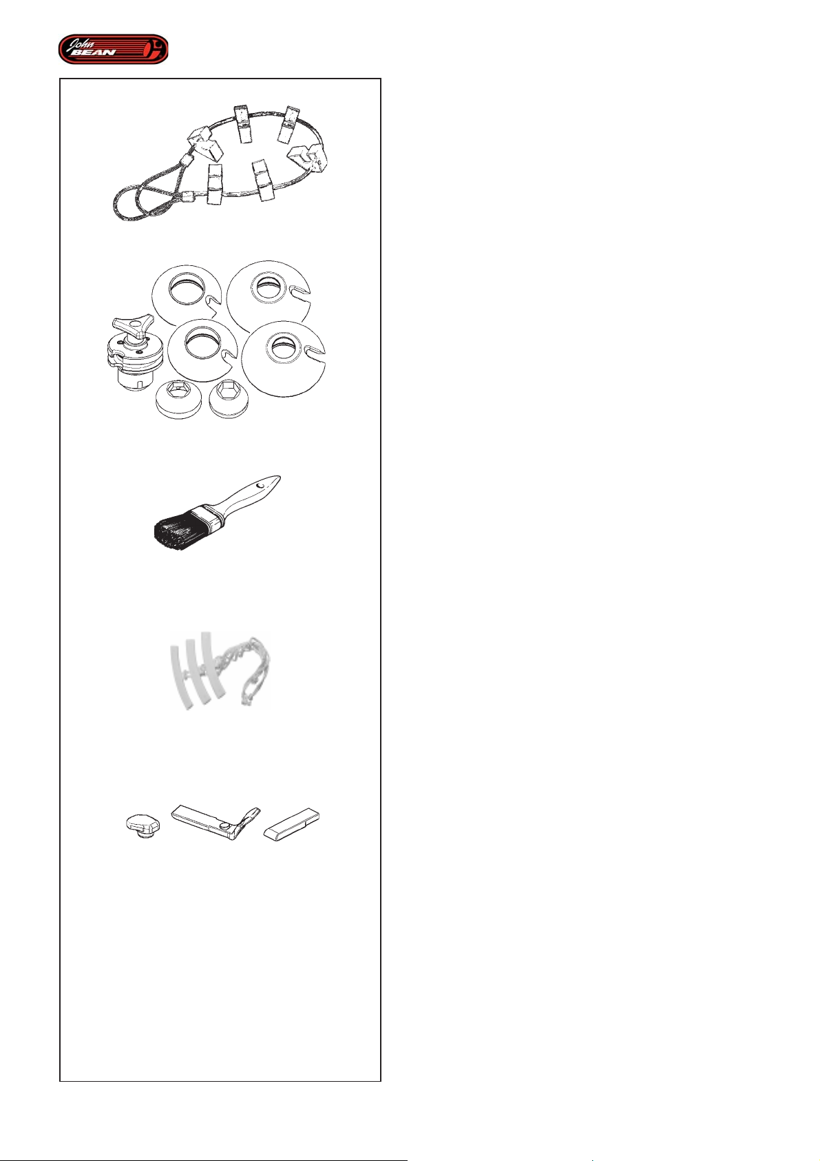
3.1-1
3.1-2
Introduction
3.1 Standard accessories
(Fig. 3.1-1)
EAA0348G65A MBP Magic Bead Pusher
This accessory consists of a set of plastic inserts fixed
so that they are equidistant on a towing cable. The
inserts hold the bead down in the rim channel,
guaranteeing easy bead insertion.
(Fig. 3.1-2)
EAA0349G82A Standard wheel clamping kit
3.1-3
3.1-4
3.1-5
(Fig. 3.1-3)
EAA0304G16A Brush
(Fig.3.1-4)
EAA0304G52A Plastic rim protection
(3 pcs.)
(Fig.3.1-5)
EAA0358G47A Spare inserts Kit for Automatic Head
Plastic inserts for mounting head and for automatic
demounting claw.
26
Operator’s Manual
QUADRIGA 1000/BB
Page 27

Introduction
Einführung
3.1 Accessoires d’origine
(Fig. 3.1-1)
EAA0348G65A MBP Groupe Inserts Presse-talon
MBP
Cet accessoire est formé d’une série d’inserts en
plastique fixes à égale distance l’un de l’autre sur un
câble de traction. Ces inserts maintiennent le talon
abaissé dans le canal de la jante, de manière à faciliter
la pénétration du talon sur la jante.
(Fig. 3.1-2)
EAA0349G82A Kit Standard Fixation roues
(Fig. 3.1-3)
EAA0304G16A Pinceau
3.1 Serienzubehör
(Abb. 3.1-1)
EAA0348G65A Gruppe von Wulst-nieder-halter-einsätzen MBP
Das Zubehör besteht aus einer Reihe von festen
Kunststoffeinsätzen, die in gleichem Abstand an einem
Zugseil angebracht sind. Diese Einsätze halten die
Wulst in der Felgenrinne unten, sodass ein einfaches
Einfügen der Wulst gewährleistet ist.
(Abb. 3.1-2)
EAA0349G82A Standardset zur Radaufspannung
(Abb. 3.1-3)
EAA0304G16A Pinsel
(Fig.3.1-4)
EAA0304G52A Protection Plastique pour jante (3
pc)
(Fig.3.1-5)
EAA0358G47A Kit Inserts de rechange pour Outil
automatique
Inserts en matière plastique pour outil de montage et
pour biseau automatique de démontage.
(Abb. 3.1-4)
EAA0304G52A Felgenschutz aus Kunststoff (3
Stück)
(Abb.3.1-5)
EAA0358G47A Wechseleinsätze Kit für
automatisches Montagewerkzeug
Einsätze aus Kunststoff für Montagewerkzeug und für
automatischen Montagefinger.
Manuel d’Utilisation QUADRIGA 1000/BBQUADRIGA 1000/BB
Betriebsanleitung
27
Page 28
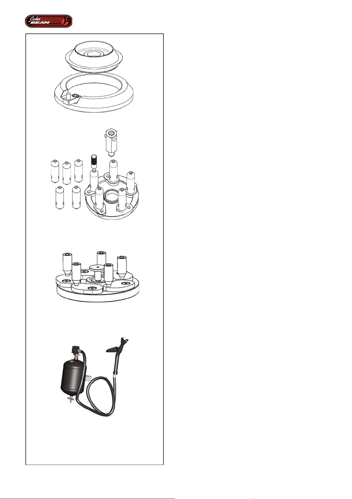
Introduction
3.2 Accessories on request
(Fig.3.2-1)
EAA0351G29A KIT FOR PICK-UP WHEELS
Allows pick-up and light truck wheels to be clamped
3.2-1
3.2-2
(Fig. 3.2-2)
EAA0351G60A KIT FOR REVERSE WHEELS
Allows wheels with reverse channel rims to be clamped
(Fig. 3.2-3)
EAA0350G16A KIT FOR CLOSED-CENTER RIMS
Allows wheels with closed-center rims (compact
clamping device included) to be clamped.
(Fig. 3.2-4)
EAA0350G36A Bead insertion kit
Facilitates beading tubeless tires with a high pressure
jet between the tire and rim.
28
3.2-3
3.2-8
Operator’s Manual
QUADRIGA 1000/BB
Page 29

Introduction
Einführung
3.2 Accessoires en option
(Fig.3.2-1)
EAA0351G29A KIT POUR ROUES PICK-UP
Permet de bloquer les roues pour pick-up & fourgon
(Fig. 3.2-2)
EAA0351G60A KIT POUR ROUES INVERSÉES
Permet de bloquer les roues avec jante à canal inversé
(Fig. 3.2-3)
EAA0350G16A KIT POUR ROUES SANS TROU
CENTRAL
Permet de bloquer les roues avec jante sans trou central
(axe compact de blocage inclus).
3.2 Zubehör auf Anfrage
(Abb.3.2-1)
EAA0351G29A BAUSA TZ FÜR PICK-UP-RÄDER
Ermöglicht das Aufspannen von Pick-Up- und
Lieferwagenrädern.
(Abb. 3.2-2)
EAA0351G60A BAUSA TZ FÜR VERKEHRTE RÄDER
Ermöglicht das Aufspannen von Rädern mit einer Felge
mit verkehrtem Bett.
(Abb. 3.2-3)
EAA0350G16A BAUSATZ FÜR RÄDER OHNE
MITTENLOCH
Ermöglicht das Aufspannen von Rädern mit einer Felge
ohne Mittenloch (enthält kompakten Aufspannstift).
(Fig. 3.2-4)
EAA0350G36A Kit d’entalonnage
Facilite l’enjantage des pneus Tubeless, au moyen d’un
jet d’air volumineux et rapide, orienté entre le pneu et
la jante.
(Abb. 3.2-4)
EAA0350G36A Bausatz zum Einsetzen der Wülste
Erleichtert das Wulsteindrücken bei schlauchlosen
Reifen mithilfe eines starken und schnellen Luftstoßes,
der auf die Stelle zwischen Reifen und Felge gerichtet
wird.
Manuel d’Utilisation QUADRIGA 1000/BBQUADRIGA 1000/BB
Betriebsanleitung
29
Page 30
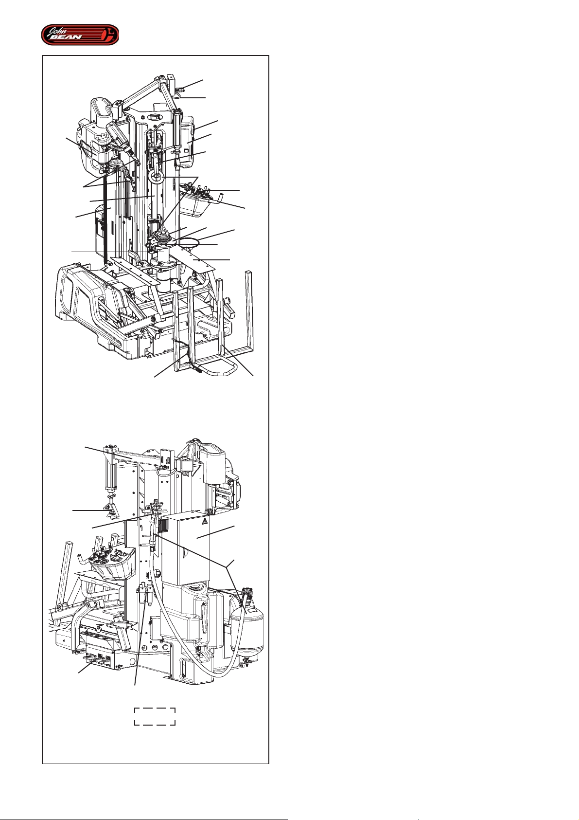
Layout
4.0 Layout
3
4
Refer to Figures 4.0-1 & 1.3-1.
Functional description of the unit:
2
27
15
1
9
16
5
10
6
17
7
13
11
12
8
19
22
18
1. User interface
2. Tool holder unit
3. Bead pusher control MH
4. Bead pusher handle MH
5. Automatic Tools
6. Tower (or column)
7. Wheel-holder flange
8. Grip pin
9. Bead breaker arm
10.Bead breaker guide
11.Clamping unit support
12.Lubricant support
13.Control panel
14.Pedal commands
15.Pressure gauge
16.Bead breaker disc
17.Locking unit
21
20
14
26
24
4.0-1
23
25
18. Front lifter
19.Upper lifter
20.Bead pusher arm
21.Bead pusher tool
22. Wheel sensor arm
23. Electrical control unit
24. Lubricator filter unit
25. GT beading device
26. Tubeless beading nozzle
27.Wheel support (Center Post)
30
1.3-1
Operator’s Manual QUADRIGA 1000/BB
Page 31

Description
Identifikation der einzelnen Teile
4.0 Description
Se reporter à la Figure 4.0-1 & 1.3-1.
Description fonctionnelle de l’unité :
1.Interface utilisateur
2.Groupe Porte-outils
3.Commande Presse-talon MH
4.Poignée Presse-talon MH
5.Outils Automatiques
6.Potence
7.Bride porte-roue
8.Axe d'accrochage
9.Bras détalonneur
10.Guide détalonneur
11.Support Groupe de Blocage
12.Support lubrifiant
13.Panneau de commandes
14.Pédalier Actionnement
4.0 Identifikation der einzelnen Teile
Siehe Abbildung 4.0-1 & 1.3-1.
Funktionsbeschreibung des Geräts:
1.Benutzerschnittstelle
2. Werkzeughaltereinheit
3. Steuerung des MH-Wulstniederhalters
4. Griff des MH-Wulstniederhalters
5. Automatische Werkzeuge
6. Säule
7. Radhalterflansch
8. Einhakstift
9. Abdrückarm
10. Führung des Abdrückarms
11. Halterung der Spanneinheit
12. Schmierhalterung
13. Steuertafel
14. Pedalsteuerung
15.Manomètre
16.Disque détalonneur
17.Groupe de blocage
18.Elévateur Frontal
19.Elévateur Supérieur
20.Bras presse-talon MH
21.Outil presse-talon MH
22.Bras Capteur Roue
23.Centrale électrique
24.Groupe filtre graisseur
25.Dispositif à rejanter talon GT
26.Buse à rejanter talon pour Tubeless
27.Porte-roue (Center post)
15. Manometer
16. Wulstablösscheibe (oben - unten)
17. Spanneinheit
18. Vordere Hebebühne (Frontheber)
19. Obere Hebebühne (oberer Heber)
20. MH-Wulstniederhalterarm
21. MH-Wulstniederhalterwerkzeug
22. Radsensorarm
23. Elektrische Steuerzentrale
24. Schmierfiltereinheit
25. GT-Wulsteindrückvorrichtung
26. Wulsteindrückdüse für schlauchlose Reifen
27. Radhalterung (Center post)
Manuel d’Utilisation QUADRIGA 1000/BBQUADRIGA 1000/BB
Betriebsanleitung
31
Page 32
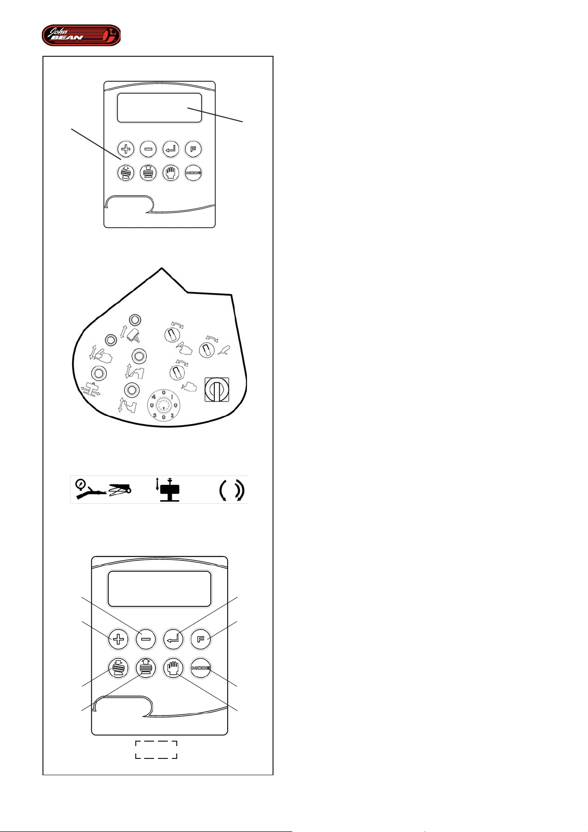
A B
Layout
4.1 Controls
Before operating the machine ensure that you have
properly understood the operation and function of all
the controls, as set out in this chapter.
The machine controls are located in three fundamental
units:
1- User interface (Fig. 4.1-1)
2- Control unit (Fig. 4.1-2)
3- Pedal command unit (Fig. 4.1-3)
4.1-1
4.1-2
4.1-3
4.1.1 User Interface
The User interface (Fig. 4.1-1) is used for entering wheel
data, selecting the type of tire and enabling/disabling
AUTOMATIC and MANUAL modes.
The panel is divided into two parts:
- a Keyboard (A, Fig. 4.1-1), for the user to operate
the software.
- a Display (B, Fig. 4.1-1), for supplying the operator
with information regarding machine settings.
Control Descriptions Figure 4.1-1
KEYBOARD Fig. 4.1-1
Key 1 and Key 2
(only in MANUAL Mode) allow you to enter data. They
are used to set the rim diameter.
Note: The rim diameter cannot be changed after
the machine sensors have registered the
required measurements. To change the
value, you need to reset the machine, i.e.
to unclamp and then reclamp the wheel.
Press and hold down both keys simultaneously to
enable the “EXPERT CHOICE” function, used to access
the advanced Automatic Subprograms described in the
relative chapter.
32
Key 3 and Key 4
2
1
5
6
4.1-1
3
4
8
7
Reserved for Service technicians.
Key 5
Enables the automatic mounting procedure.
Key 6
Enables the automatic demounting procedure.
Key 7
MANUAL mode: press this key to exit the AUTOMATIC
mode. In any phase of the procedure this key will abort
the automated part that is operating. Remove any error
or warning messages, to continue the operation.
Key 8
Used to select the type of tire: NORMAL, SPORT, or
SOFT, see the Tire Type chapter.
Operator’s Manual QUADRIGA 1000/BB
Page 33

Description
Identifikation der einzelnen Teile
4.1 Commandes
Avant de travailler avec la machine, s’assurer d’avoir
bien compris la position et les fonctions des
commandes , comme il est décrit dans ce chapitre.
Les commandes de la machine se trouvent sur trois
unités fondamentales :
1- Interface Utilisateur (Fig. 4.1-1)
2- Unité de Commande (Fig. 4.1-2)
3- Pédalier Actionnement (Fig. 4.1-3)
4.1.1 Interface Utilisateur
L'interface Utilisateur (Fig. 4.1-1) sert à saisir les données
relatives à la roue, sélectionner le type de pneu et activer/
désactiver les fonctions AUTOMATIQUE et MANUEL.
Le pupitre comprend deux parties :
- Clavier (A, Fig. 4.1-1), avec lequel l'utilisateur
intervient sur le logiciel.
- Afficheur (B, Fig. 4.1-1), qui restitue à l'opérateur
les informations relatives aux paramétrages effectués.
4.1 Maschinenbedienung
Vor Inbetriebnahme der Reifenmontiermaschine sollten
Sie sich mit der Lage und Funktionsweise aller
Steuerteile vertraut machen, wie sie in diesem Kapitel
erklärt sind.
Die Steuerelemente der Maschine befinden sich an den
drei wichtigsten Einheiten:
1- Bedienerschnittstelle (Abb. 4.1-1)
2- Steuereinheit (Abb. 4.1-2)
3- Pedalsteuerung (Abb. 4.1-3)
4.1.1 Bedienerschnittstelle
Die Bedienerschnittstelle (Abb. 4.1-1) dient zur Eingabe
der Raddaten, zur Auswahl des Reifentyps und zur
Aktivierung/Deaktivierung der Betriebsarten AUTOMATIK
und MANUELL.
Die Tafel ist in zwei Teile geteilt:
- Tastatur (A, Abb. 4.1-1), über die der Benutzer das
Programm bedient.
- Display (B, Abb. 4.1-1), auf dem der Bediener die
Informationen über die Einstellungen ablesen kann.
Description des Commandes Figure 4.1-1
CLA VIER Fig. 4.1-1
T ouche 1 et Touche 2
(dans le Mode MANUEL seulement) permettent de saisir
les données. Saisie du diamètre de la jante.
Remarque : Il n'est pas possible de modifier le
diamètre de la jante après l'excitation des
capteurs de contrôle de la machine. Pour
modifier la valeur, il est nécessaire de
remettre à zéro c'est-à-dire débloquer et
bloquer à nouveau la roue.
La pression simultanée des deux touches pendant
quelques secondes autorise la fonction "EXPERT
CHOICE" pour l'accès avancé aux programmes
secondaires automatiques, voir la rubrique s'y rapportant.
T ouche 3 et Touche 4
Réservés aux techniciens du Service.
T ouche 5
Autorise la procédure automatique de montage.
T ouche 6
Autorise la procédure automatique de démontage.
T ouche 7
Mode MANUEL: provoque la sortie du Mode
AUTOMATIQUE. A tout moment de la procédure, il
permet de tronquer l'automatisme en cours. Effacer les
éventuels messages d’erreur ou de mise en garde, pour
que l’équipement puisse reprendre à fonctionner
normalement.
T ouche 8
Choix du type de pneu : NORMAL, SPORT, SOFT, voir
rubrique Type de Pneu.
Beschreibung der Steuerelemente Abbildung 4.1-1
T AST A TUR Abb. 4.1-1
T aste 1 und T aste 2
(nur im MANUALBETRIEB) ermöglichen es, Daten
einzugeben. Mit ihnen stellt man den Felgendurchmesser ein.
Anmerkung: Es ist nicht möglich, den
Felgendurchmesser zu ändern, nachdem
die Maschine ihn mithilfe der Sensoren
erfasst hat. Um den Wert zu ändern,
muss man alles zurücksetzen, d.h. das
Rad ab- und dann wieder aufspannen.
Wenn man diese Tasten einige Sekunden lang
gleichzeitig drückt, wird die Funktion "EXPERT CHOICE"
aktiviert, mit der fortgeschrittene Benutzer Zugang zu
den automatischen Unterprogrammen haben; siehe dazu
das entsprechende Kapitel.
T aste 3 und T aste 4
Sie sind den Kundendiensttechnikern vorbehalten.
T aste 5
Zur Aktivierung des automatischen Montagevorgangs.
T aste 6
Zur Aktivierung des automatischen Demontagevorgangs.
T aste 7
MANUALBETRIEB: führt zum Beenden des
AUTOMATIKBETRIEBS. Dadurch wird in jeder Phase
des Vorgehens der gerade laufende automatische
Vorgang abgebrochen. Außerdem werden damit
eventuell vorhandene Fehlermeldungen oder Warnungen
entfernt, so dass man weiterarbeiten kann.
T aste 8
Auswahl des Reifentyps: NORMAL, SPORT, SOFT;
siehe dazu das Kapitel "Reifentyp".
Manuel d’Utilisation QUADRIGA 1000/BBQUADRIGA 1000/BB
Betriebsanleitung
33
Page 34
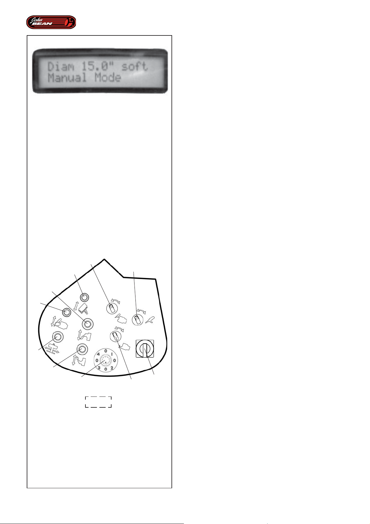
4.1-4
Layout
DISPLAY Fig. 4.1-4
The Display shows the rim diameter set, the type of
tire and the current operating mode: MANUAL mode,
AUTOMATIC MOUNTING mode, AUTOMATIC
DEMOUNTING mode, "EXPERT CHOICE" mode.
Figure 4.1-4 shows the Display in operation.
4.1.2 Control Panel
The Control Panel features a series of selectors and
levers that can be used in MANUAL mode to activate
most of the machine components.
When in any AUTOMATIC mode, only this lever (2, Fig.
4.1-2) is enabled to activate the automatic procedure
for moving the tool carriage vertically. For details of how
to use this, see the Individual Automated Parts chapter.
Control Descriptions Figura 4.1-2
Lever 1
This activates the automatic wheel loading and
unloading procedure from the ground to the work
6
1
7
4
2
3
5
9
4.1-2
8
10
position and viceversa.
Lever 2
This moves the Tool Holder Unit vertically. It also enables
the activation of the automatic procedures.
Lever 3
This moves the Wheel Support (Center Post)
horizontally.
Lever 4
This activates the upper bead breaker disk.
Lever 5
This activates the lower bead breaker disk
Selector 6
This moves tool arm “1”.
Selector 7
This turns tool “1”.
Selector 8
This moves tool arm “2”.
Selector 9 (knob)
This is used to select the “EXPERT CHOICE” mode
automatic subprograms.
34
10 Main switch
Main on/off switch.
Operator’s Manual QUADRIGA 1000/BB
Page 35

Description
Identifikation der einzelnen Teile
AFFICHEUR Fig. 4.1-4
L'afficheur indique le diamètre de la jante paramétré, le
type de pneu, le mode de fonctionnement courant : Mode
MANUEL, Mode MONTAGE AUTOMATIQUE, Mode
DEMONTAGE AUTOMATIQUE, Mode "EXPERT
CHOICE".
La Figure 4.1-4 représente l'afficheur en fonction.
4.1.2 Unité de commande
L'unité de commande présente une série de sélecteurs
et manipulateurs par le biais desquels il est possible
dans le Mode MANUEL de commander la plupart des
composants de la machine.
Dans le Mode AUTOMATIQUE, le levier (2, Fig. 4.1-2)
est le seul autorisé à donner lieu à la procédure
automatique, à savoir le déplacement vertical du chariot
outils. Son utilisation est décrite dans la rubrique
Automatismes.
DISPLA Y Abb. 4.1-4
Am Display werden der eingestellte Felgendurchmesser,
der Reifentyp und die aktuelle Betriebsart angezeigt:
MANUALBETRIEB, AUTOMATISCHE MONTAGE,
AUTOMATISCHE DEMONTAGE, "EXPERT CHOICE".
In der Abbildung 4.1-4 ist das Display im Betrieb
dargestellt.
4.1.2 Steuereinheit
Die Steuereinheit umfasst eine Reihe von Wählschaltern
und Bedienelementen, mit denen der Großteil der
Komponenten der Maschine im MANUALBETRIEB
betätigt werden kann.
In einer der AUTOMATISCHEN BETRIEBSARTEN ist
es nur mit dem Hebel (2, Abb. 4.1-2) möglich, den
automatischen Vorgang durchzuführen, was dem
vertikalen Verschieben des Wagens entspricht. Die
Anwendung ist im Kapitel "Automation" beschrieben.
Description des Commandes Figure 4.1-2
1 Manette
Active la procédure automatique de chargement et
déchargement des roues, du sol à la position de travail
et vice-versa.
2 Manette
Active le mouvement vertical du Groupe Porte-outils.
Donne également l'autorisation au déroulement des
procédures automatiques.
3 Manette
Active le mouvement horizontal du Porte-roue (Center
Post).
4 Manette
Mouvement du disque détalonneur supérieur
5 Manette
Mouvement du disque détalonneur inférieur
6 Sélecteur
Mouvement du bras de l'outil "1".
7 Sélecteur
Rotation de l'outil "1".
8 Sélecteur
Mouvement du bras de l'outil "2".
9 Sélecteur (knob)
Sélection de programmes secondaires automatiques,
Mode "EXPERT CHOICE".
10 Sectionneur
Interrupteur général.
Beschreibung der Steuerelemente Abbildung
4.1-2
1 Bedienelement
Zur Aktivierung des automatischen Vorgangs zum Aufund Abladen der Räder vom Boden in die
Betriebsstellung und umgekehrt.
2 Manipolatore
Zur Aktivierung der vertikalen Bewegung der
Werkzeughaltereinheit. Außerdem zur Freigabe der
Durchführung der automatischen Vorgänge.
3 Bedienelement
Zur Aktivierung der horizontalen Bewegung der
Radhalterung (Center Post) .
4 Bedienelement
Bewegung der oberen Wulstablösscheibe
5 Bedienelement
Bewegung der unteren Wulstablösscheibe
6 Wählschalter
Bewegung des Arms des Werkzeugs "1".
7 Wählschalter
Drehung des Werkzeugs "1".
8 Wählschalter
Bewegung des Arms des Werkzeugs "2".
9 Wählschalter(knopf)
Auswahl der automatischen Unterprogramme;
Betriebsart "EXPERT CHOICE".
10 Trennschalter
Hautpschalter.
Manuel d’Utilisation QUADRIGA 1000/BBQUADRIGA 1000/BB
Betriebsanleitung
35
Page 36
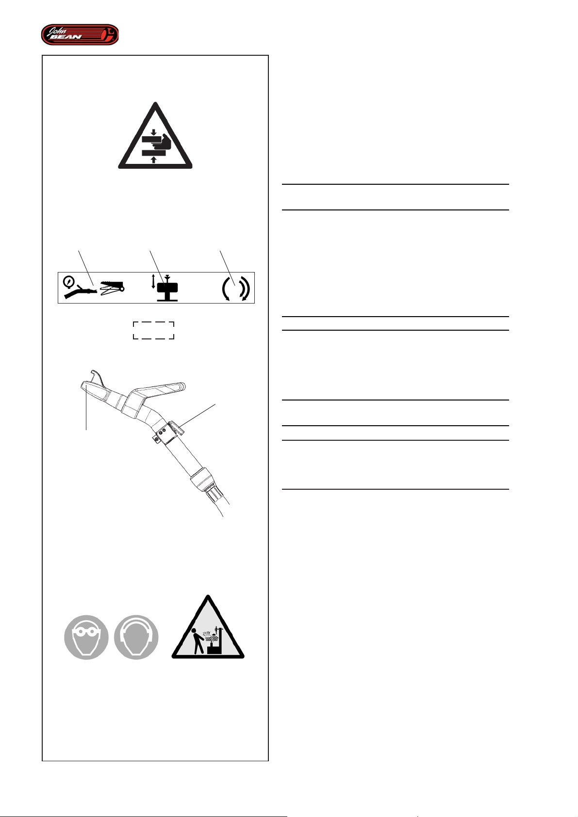
Layout
4.1.3 Pedal Command Unit
Some controls exist only in the pedal command unit
located on the right of the machine.
The pedal commands leave both the operator’s hands
free to perform certain operations perfectly.
4.1-5
1 2 3
4.1-3
5
Figure 4.1-5
WARNING:
DANGER OF HANDS BEING CRUSHED.
Figure 4.1-3, 1 - Beading pedal:
It is used to bead the tires on the rim, to inflate with air
through the rim valve and with the blast through the
beading nozzle (5, Fig.4.1-6).
To perform the “blast”:
HOLD THE BEADING NOZZLE FIRMLY.
• Operate the pedal command (1, Fig.4.1-3) fully
and at the same time use the button (4, Fig.4.1-6) on
the beading nozzle.
Figure 4.1-7
4
WARNING:
DANGER OF TIRE EXPLOSION
WARNING:
THESE OPERATIONS MAY BE DANGEROUS.
OBSERVE THE SAFETY INSTRUCTIONS SET OUT
IN THE PLATES
36
4.1-6
4.1-7
Figure 4.1-3, 2 - Clamping/Unclamping Pedal:
This is used to clamp and unclamp the wheel to and
from the Wheel Support.
• Press and release the pedal to clamp and
unclamp the rim on the Wheel Support Flange
Figure 4.1-3, 3 - Rotation Pedal:
This activates rotation in both directions.
• Lift the pedal to rotate counterclockwise.
Note: The machine has two clockwise rotation
speeds, based on the pedal pressure.
• Partially press the pedal (first click) for the first speed
clockwise rotation.
• Press the pedal fully (second click) for the second
speed clockwise rotation.
Operator’s Manual QUADRIGA 1000/BB
Page 37

Description
Identifikation der einzelnen Teile
4.1.3 Pédalier Actionnement
Certaines commandes sont présentes exclusivement
dans le pédalier, situé sur le côté droit de la machine.
Les commandes à pédale permettent à l'opérateur de
disposer des deux mains pour mieux gérer certaines
phases opérationnelles.
Figure 4.1-5
A TTENTION :
DANGER D'ECRASEMENT MAINS.
Figure 4.1-3, 1 - Pédale à rejanter talon :
Permet de rejanter le talon du pneu, de le gonfler par le
biais de la valve de la jante et avec le “blast” par le biais
de la buse de rejantage (5, Fig.4.1-6).
Pour l’exécution du “blast”:
TENIR FERMEMENT LA BUSE A REJANTER.
• Actionner la commande à pédale (1, Fig.4.1-3)
à fond et presser en même temps la touche (4, Fig.4.1-
6) située sur la buse de rejantage.
4.1.3 Pedalsteuerung
Einige Steuerelemente befinden sich ausschließlich an
der Pedalsteuerung, die sich an der rechten Seite der
Maschine angebracht ist.
Durch die Pedalsteuerungen hat der Bediener beide
Hände zur Verfügung, um einige Arbeitsphasen perfekt
verwalten zu können.
Abbildung 4.1-5
ACHTUNG:
QUETSCHGEFAHR FÜR DIE HÄNDE.
Abbildung 4.1-3, 1 - Pedal zum Wulsteindrücken:
Hiermit können die Radwülste in die Felge eingedrückt
werden; dies geschieht durch Füllen mit Luft über das
Felgenventil und mit dem „Blast” (Luftstoß) durch die
Wulsteindrückdüse (5, Abb.4.1-6).
Um den “Blast” auszuführen:
DIE WULSTEINDRÜCKDÜSE SEHR FEST HALTEN.
• Die Pedalsteuerung (1, Abb.4.1-3) ganz nach unten
drücken und gleichzeitig die Taste (4, Abb.4.1-6) an
der Wulsteindrückdüse betätigen.
Figure 4.1-7
A TTENTION:
RISQUE D'EXPLOSION DU PNEU
A TTENTION:
CES MANŒUVRES SONT DANGEREUSES.
RESPECTER LES CONSIGNES DE SECURITE
INDIQUEES PAR LES PLAQUETTES APPOSEES
SUR LA MACHINE.
2- Figure 4.1-3, 2 - Pédale de Blocage/Déblocage:
Elle sert à bloquer et débloquer les roues du Support
Roue.
• Presser et relâcher la pédale pour obtenir soit le
blocage, soit le déblocage de la jante sur la flasque
porte roue.
3- Figure 4.1-3, 3 - Pédale Rotation:
Active la rotation dans les deux sens.
• Soulever la pédale pour obtenir la rotation antihoraire.
Nota: La machine prévoit deux vitesses dans le sens
de rotation horaire, en fonction de la pression
de la pédale.
• Presser légèrement la pédale (en première) pour
obtenir la rotation dans le sens horaire en première.
• Presser la pédale à fond (en deuxième) pour obtenir
la rotation dans le sens horaire en deuxième.
Abbildung 4.1-7
ACHTUNG:
GEFAHR: REIFEN KÖNNTE EXPLODIEREN
ACHTUNG:
DIESE VORGÄNGE SIND GEFÄHRLICH. BEFOLGEN
SIE DIE VORGESCHRIEBENEN
SICHERHEITSMASSNAHMEN AUF DEN SCHILDERN
Abbildung 4.1-3, 2 - Pedal zum Auf-/Abspannen:
Es wird verwendet, um die Räder auf die Radhalterung
aufzuspannen und davon abzuspannen.
• Das Pedal drücken und loslassen, um die Felge
am Radflansch auf- bzw. abzuspannen.
Abbildung 4.1-3, 3 - Pedal zur Drehung:
Aktiviert die Drehung in beide Richtungen.
• Das Pedal anheben, um die Drehung gegen den
Uhrzeigersinn zu erhalten.
Anm.: Die Maschine bietet, je nach Stärke des Drucks
auf das Pedal, zwei Geschwindigkeiten bei der
Drehung im Uhrzeigersinn.
• Für die Drehung im Uhrzeigersinn mit der ersten
Geschwindigkeit das Pedal teilweise drücken (bis
zum ersten Klicken).
• Für die Drehung im Uhrzeigersinn mit der zweiten
Geschwindigkeit das Pedal bis nach unten drücken
(zweites Klicken).
Manuel d’Utilisation QUADRIGA 1000/BBQUADRIGA 1000/BB
Betriebsanleitung
37
Page 38
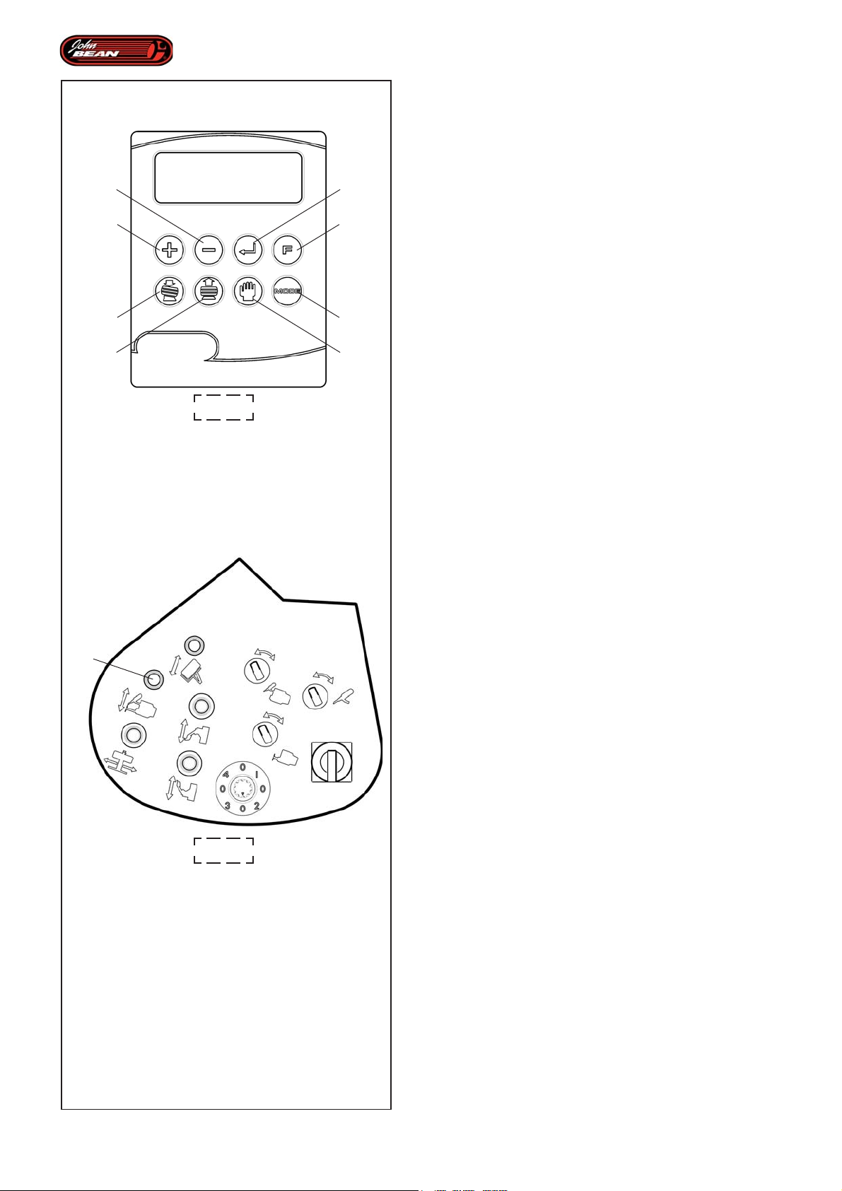
Layout
4.2 Operating Automated Parts
The Super Automatic Tire Changer operates according
to reset work cycles (Mounting and Demounting
2
1
5
6
4.1-1
3
4
8
7
Programs) that can be selected by the operator. Using
these cycles all movements are controlled by the
machine.
The operator is only required to perform a number of
selections and settings on the User Interface keyboard,
after which the various work cycles can begin.
Note: Pressing the Unclamp From Rim pedal
interrupts the work cycle that is in progress
and deletes the data acquired previously.
At this point, to run another automatic
program you will need to first perform a
data acquisition operation.
The software operates the entire automatic process in
a series of clearly defined steps that are named in the
manual as follows:
Work cycle:
This is the complete tire change procedure, or rather,
the set of Demounting and Mounting Programs.
Program:
This refers to the operations involving Demounting and
Mounting the tire on the rim. The control panel has a
special key for each of the two selections.
2
4.1-2
Subprogram:
This identifies the subdivision of the programs into the
individual programs performed in both programs.
The figure (Fig.4.2-1) shows the Programs and the
respective Subprograms that make them up.
Phase:
This is a further division of the Subprogram. The
machine stops all movements automatically and emits
a warning “beep”. The operator must release the lever
(2, Fig.4.1-2) to confirm the temporary stop request
and then activate lever “2” again to continue the
automatic procedure.
Having loaded the wheel or even just the rim, for the
automated parts to operate correctly you need to:
• Set the value corresponding to the rim
diameter, using the + and – keys (1 and 2, Fig.4.1-1).
• Select the required Wheel Mode. By default
the machine always proposes NORMAL, (see the
Selecting Wheel Mode chapter).
• Select the required program using these keys:
38
6, Fig.4.1-1 - Automatic Demounting;
(Full Tire Remove) if a complete wheel with
the bead inserted is clamped onto the Wheelholder
Flange.
Operator’s Manual QUADRIGA 1000/BB
Page 39

Description
Identifikation der einzelnen Teile
4. 2 Fonctionnement Automatismes
Le Démonte-pneus Super Automatique opère suivant
des cycles de travail pré-paramétrés (Programmes de
Montage et Démontage) sélectionnables par l'opérateur,
par le biais desquels chaque mouvement est contrôlé
par la machine.
Il ne reste à l'opérateur qu'à effectuer quelques
sélections et paramétrages initiaux avec le clavier de
l'Interface Utilisateur pour que l'usinage proprement dit
puisse avoir lieu.
NB: La pression de la pédale de déblocage de
la jante provoque l'interruption du cycle
d'usinage en cours et la perte des données
acquises précédemment. L'exécution d'un
programme automatique successif sera à
ce stade nécessairement précédé par
l'opération d'acquisition des données.
Le logiciel gère les opérations et tout le processus
automatique, à travers des pas bien définis et
dénommés dans ce manuel comme suit:
Cycle de travail:
Il s'agit de la procédure complète de remplacement du
pneu, c'est-à-dire l'ensemble des Programmes de
Démontage et Montage.
Programme :
Désigne les opérations distinctes de démontage et montage
du pneu sur la jante. Le pupitre opérateur comprend une
touche distincte pour chacune des deux opérations.
Programme secondaire :
Identifie la subdivision des programmes en opérations
invididuelles effectuées, présentes dans les deux
Programmes.La figure (Fig.4.2-1) montre les
Programmes et les programmes secondaires dont ils
sont formés.
Phase :
Il s'agit de l'ultérieure subdivision d'un programme
secondaire. La machine présente automatiquement un
arrêt des mouvements et émet un signal sonore "bip"
d'avertissement. L'opérateur doit relâcher la Manette
(2, Fig.4.1-2) pour confirmer la demande d'arrêt
momentané, puis actionner à nouveau la Manette "2",
pour reprendre la procédure automatique en cours.
4.2 Funktionsweise der Automation
Die automatische Reifenmontiermaschine arbeitet nach
voreingestellten Betriebszyklen (Montage- und
Demontageprogramme), die vom Bediener angewählt
werden können. Damit wird jede Bewegung von der
Maschine gesteuert.
Der Bediener selbst muss nur am Anfang wenige Elemente
auswählen und einstellen, danach kann die eigentliche
Bearbeitung beginnen.
Anmerkung: Wenn man das Pedal zum Abspannen der
Felge drückt, führt dies zur Unterbrechung
des laufenden Betriebszyklus und die
davor erfassten Daten gehen verloren.
Wenn man daraufhin ein automatisches
Programm ausführen möchte, muss man
zuerst wieder die Daten erfassen.
Das Programm verwaltet die Operationen und den
gesamten automatischen Prozess über festgelegte
Schritte, die in der Anleitung wie folgt genannt werden:
Betriebszyklus:
Dies ist das vollständige Vorgehen zum Reifenwechsel,
d.h. die Gesamtheit der Programme zur Demontage und
Montage.
Programm:
Dies bezieht sich auf die einzelnen Operationen des
Entfernens und Montierens des Reifens an der Felge. Die
Steuertafel hat eine eigene Taste für jede der beiden
Auswahlen.
Unterprogramm:
Dies ist die Bezeichnung für die Unterteilung der Programme
in einzelne, abgeschlossene Operationen, die in beiden
Programmen vorhanden sind.
In der Abbidlung (Abb.4.2-1) sind die Programme und die
jeweiligen Unterprogramme, aus denen sie bestehen,
dargestellt.
Phase:
Sie ist die weitere Unterteilung eines Unterprogramms. Die
Maschine hält die Bewegungen automatisch an und gibt
ein akustisches Signal (Piepton) aus. Der Bediener muss
das Bedienelement (2, Abb.4.1-2) loslassen, um die
Anforderung zum zeitweiligen Halt zu bestätigen, und
danach das Bedienelement "2" wieder betätigen, um den
laufenden automatischen Vorgang wieder aufzunehmen.
Pour le déroulement correct des automatismes, après
le chargement de la roue ou de la jante uniquement, il
est nécessaire de:
• Paramétrer la valeur correspondant au
diamètre de la jante, avec les touches + et – (1 et 2,
Fig.4.1-1).
• Sélectionner le Mode Roue souhaité. De
base, la machine présente toujours NORMAL, (voir
rubrique Sélection du Mode Roue).
• Sélectionner le programme souhaité avec les touches:
6, Fig.4.1-1 - Démontage Automatique;
(Full Tire Remove); si une roue complète avec
jante est bloquée sur la Bride Porte-roue.
Manuel d’Utilisation QUADRIGA 1000/BBQUADRIGA 1000/BB
Damit die Automation ordnungsgemäß abläuft, muss man
daher nach dem Laden des Rads oder nur der Felge
Folgendes tun:
• Mit den Tasten + und - (1 und 2, Abb.4.1-1) den
Wert des Felgendurchmessers eingeben.
• Den gewünschten Radtyp wählen. Als Standard
gibt die Maschine immer NORMAL an (siehe das Kapitel
"Auswahl des Radmodus").
• Das gewünschte Programm mit folgenden Tasten
wählen:
6, Abb.4.1-1 - Automatische Demontage
(Full Tire Remove); Wenn am Radhalterflansch
ein vollständiges Rad mit Wulst aufgespannt ist.
Betriebsanleitung
39
Page 40
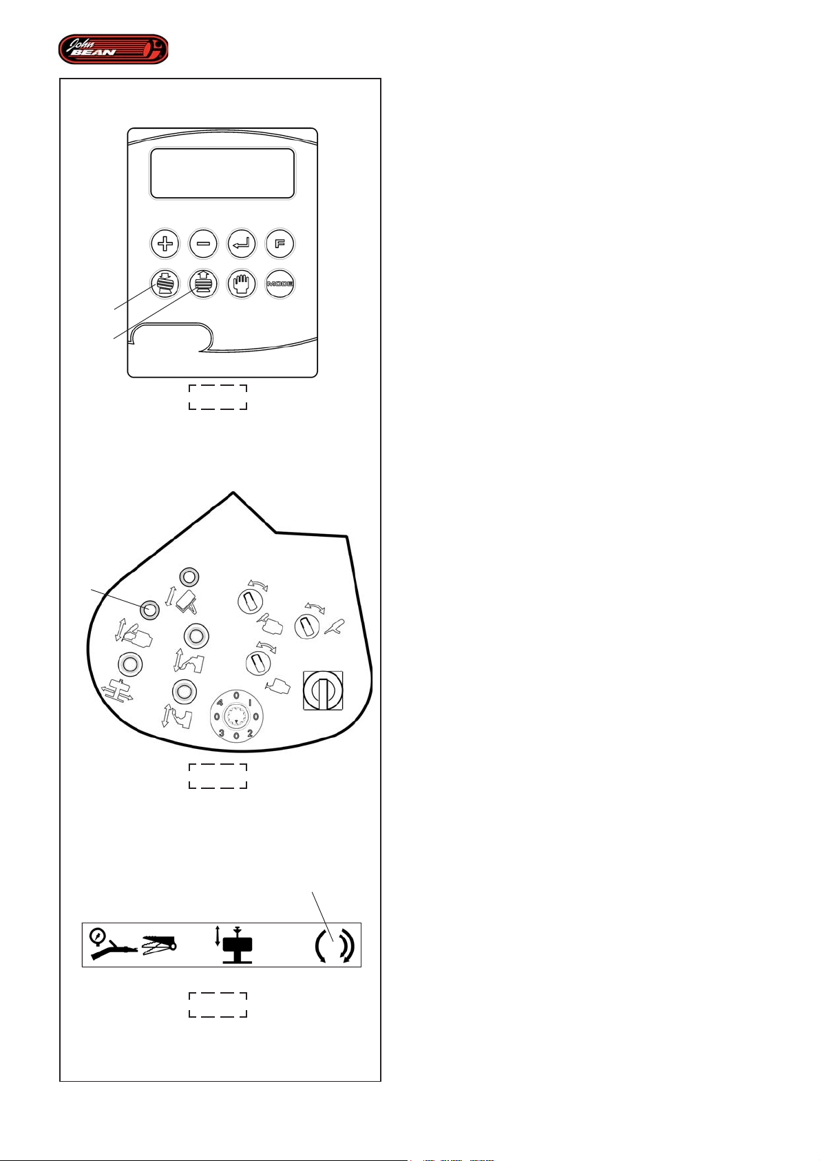
Layout
or,
5, Fig.4.1-1 - Automatic Mounting ;
(Full Tire Mount); if just a rim with no tire is
clamped onto the Wheelholder Flange.
At this point to start the actual program the operator
needs to
• keep the lever (2, Fig.4.1-2) on the Control Unit
activated until all the individual work phases are
enabled and performed in the correct order for the
entire course of the program.
This guarantees that the operator is in constant control
of all the tire changer movements and can interrupt it
5
6
4.1-1
rapidly in the event of problems or malfunctioning.
The operator can choose, at any time, to release the
lever and interrupt the cycle. If the main on/off switch is
left on and the operator does not exit the Automatic
modes currently in progress, work can be continued
from wherever the operator chooses.
Activating the lever in the opposite direction runs all
the movements in reverse until the tools are in the idle
position.
Note: The definition "Idle Position" refers to the
operating parts of the machine (bead
breaking tools and disks) and indicates that
they have moved right away from the tire
and are not currently in operation.
2
4.2.1 Automatic Demounting Program
Having completed the preliminary operations and having
pressed the Automatic Demounting key (6, Fig.4.1-
1), the machine is ready to run the Subprograms in
the tire demounting program.
4.1-2
3
Within the Automatic Demounting Program the following
Subprograms are run in this order:
- Bead breaking
- Removing the upper bead
- Removing the lower bead
40
4.1-3
Note: Every time the machine interrupts an
automated phase, the operator must
release the lever (2, Fig.4.1-2) and perform
the required operation (described in the
Operations chapter).
Operator’s Manual QUADRIGA 1000/BB
Page 41

Description
Identifikation der einzelnen Teile
ou bien,
5, Fig.4.1-1 - Montage Automatique ;
(Full Tire Mount); si une jante nue, sans pneu,
est bloquée sur la Bride Porte-Roue.
A ce stade pour commencer le programme proprement
dit, l'opérateur doit nécessairement
• maintenir la Manette activée (2, Fig.4.1-2) sur l'Unité
de Commande, pour que les phases de travail se
réalisent et se suivent en séquence, pendant tout le
déroulement du programme.
Cette condition garantit un contrôle constant de la part
de l'opérateur sur tous les mouvements du démontepneu, avec la possibilité d'interrompre rapidement
l'opérativité en cas de problèmes et d'erreurs de
fonctionnement.
L'opérateur, à sa propre discrétion, peut relâcher la
Manette et interrompre le cycle à tout moment , à
condition que l'alimentation électrique soit maintenue
et qu'on ne sorte pas des Modes Automatiques en
cours. Il sera ensuite possible de reprendre le travail
au moment souhaité.
L'action dans le sens opposé de la Manette produit
l'exécution en marche arrière de tous les mouvements,
jusqu'à ce que les outils ne soient pas conduits en
position de "hors travail".
NB: La définition de "Hors travail" se réfère aux
éléments opérants de la machine (outils
et disques détalonneurs) et indique qu'ils
se trouvent en position de repos,
complètement à l'écart du pneu.
Oder,
5, Abb.4.1-1 - Automatische Montage
(Full Tire Mount); Wenn am Radhalterflansch
eine nackte Felge, d.h. ohne Reifen, aufgespannt ist.
Nun muss der Bediener, um das eigentliche Programm
zu starten, Folgendes tun
• Das Bedienelement (2, Abb.4.1-2) an der
Steuereinheit so lange betätigen, bis die einzelnen
Arbeitsphasen ausgeführt sind, damit sie
nacheinander ablaufen, bis das gesamte Programm
ausgeführt ist.
Diese Maßnahme gewährleistet, dass der Bediener
sämtliche Bewegungen der Reifenmontiermaschine
ständig unter Kontrolle hat, und dass er die Möglichkeit
hat, den Betrieb bei Problemen oder Funktionsstörungen
rasch zu unterbrechen.
Der Bediener hat jederzeit die Möglichkeit, das
Bedienelement loszulassen und den Zyklus zu
unterbrechen, sofern die Stromzufuhr nicht abgeschaltet
wird und die laufenden automatischen Betriebsarten nicht
beendet werden. Die Arbeit kann dann zu dem
gewünschten Zeitpunkt wieder aufgenommen werden.
Die Betätigung des Bedienelements in der
entgegengesetzten Richtung führt zur umgekehrten
Ausführung aller Bewegungen, bis die Werkzeuge
schließlich in die Stellung "außer Betrieb" geführt werden.
Anmerkung: Die Bezeichnung "außer Betrieb"
bezieht sich auf die Arbeitselemente
der Maschine (Werkzeuge und
Wulstablösscheiben) und gibt an,
dass sich diese in der Ruhestellung,
ganz vom Reifen gelöst, befinden.
4.2.1 Programme de Démontage
Automatique
Après avoir terminé les opérations préliminaires et
pressé ensuite la touche (6, Fig.4.1-1) Démontage
Automatique, la machine est prédisposée pour
l'exécution des programmes secondaires relatifs au
programme de démontage du pneu.
A l'intérieur du Programme de Démontage Automatique
se suivent en séquence les Programmes Secondaires:
- Déjantage
- Décoller le talon supérieur
- Décoller le talon inférieur
NB: Chaque fois que l'appareil présente l'interruption
d'une phase de l'automatisme, l'opérateur
doit relâcher la Manette (2, Fig.4.1-2) et
effectuer l'opération nécessaire (voir
rubrique Opérativité).
4.2.1 Programm zur automatischen
Demontage
Wenn die Vorbereitungen abgeschlossen sind und
danach die Taste (6, Abb.4.1-1) für die automatische
Demontage gedrückt wurde, ist die Maschine zur
Ausführung der Unterprogramme des Programms zur
Demontage des Reifens bereit.
Innerhalb des Programms der automatischen Demontage
laufen nacheinander folgende Unterprogramme ab:
- Abdrücken der Wülste
- Entfernung des oberen Wulstes
- Entfernung des unteren Wulstes
Anmerkung: Jedes Mal, wenn die Maschine eine Phase
der Automation unterbricht, muss der
Bediener das Bedienelement (2,
Abb.4.1-2) loslassen und die nötige
Tätigkeit (die im Kapitel "Betrieb"
beschrieben ist) ausführen.
Manuel d’Utilisation QUADRIGA 1000/BBQUADRIGA 1000/BB
Betriebsanleitung
41
Page 42
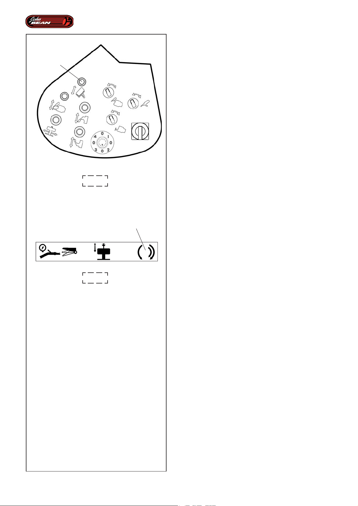
Layout
BEAD BREAKING
When this Subprogram is running, the data required for
the successive work cycles is acquired automatically
2
4.1-2
by the sensors fitted on the Bead Breaker Arms and
using a Laser detector. The data acquired includes the
positions of the upper and lower rim edge, which are
indispensable for performing the required operations.
During upper or lower bead breaking operations, you
can release the lever (2, Fig.4.1-2) and continue the
rotation procedure using the pedal (3, Fig.4.1-3). The
bead breaking disk is not allowed to move so the operator
can lubricate the entire circumference freely to increase
the efficiency of the operation.
In the same way the rotation pedal can be released at
any time and bead breaking can be resumed using the
lever (2, Fig.4.1-2).
When the machine is performing the lower bead breaking
operation it also acquires the rim width data.
The Bead breaking Subprogram is completed by a laser
scan of the upper rim flange.
4.1-3
3
REMOVING THE UPPER BEAD
Having completed the bead breaking operations, keep
the lever (2, Fig.4.1-2) activated to move the bead
breaking disks into the idle position. The Upper Bead
Removal operation continues automatically with the
upper tool being moved up until it grips onto the upper
bead.
If the bead slips back into its housing on the rim it
should be pressed back into the groove using the bead
pusher.
This phase is completed by a temporary stop (signalled
by a beep) in which the operator is requested to inspect
that everything is correct before proceeding.
WARNING:
IF THE BEAD IS POSITIONED CORRECTLY IN THE
RIM DEAD CENTER, WORK CAN PROCEED.
The Subprogram continues by extracting the upper bead
and finishes when the tools are positioned correctly for
extracting the lower bead.
The operation is now finished and the automated cycle
can proceed directly to the next Subprogram.
42
Operator’s Manual QUADRIGA 1000/BB
Page 43

Description
Identifikation der einzelnen Teile
DEJANT AGE
'acquisition des données utiles aux usinages
successifs se déroule automatiquement au cours de
ce programme secondaire, par le biais de capteurs
appliqués aux outils qui décollent le pneu de la jante et
d'un détecteur laser. Les données se réfèrent aux
positions du bord supérieur et inférieur de la jante et
sont indispensables pour la suite des opérations.
Au cours des opérations de Déjantage, supérieur ou
inférieur, il est possible de relâcher la Manette (2,
Fig.4.1-2) et poursuivre la rotation avec la pédale (3,
Fig.4.1-3), les mouvements du disque détalonneur sont
inhibés et l'opérateur peut librement lubrifier le talon
sur toute la circonférence, pour mieux travailler.
De même, il sera possible à tout moment de relâcher
la pédale de rotation et reprendre le déjantage avec la
Manette (2, Fig.4.1-2) .
Pendant le déjantage du talon inférieur, la machine
effectue simultanément l'acquisition de la largeur du
pneu.
Le programme secondaire de Déjantage se termine
avec l'opération de balayage laser du bord supérieur
du cercle.
ABDRÜCKEN DER WÜLSTE
Im Laufe dieses Unterprogramms werden durch
Sensoren, die am Abdrückarm befestigt sind, und
mithilfe eines Lasersensors automatisch die Daten
erfasst, die für die folgenden Bearbeitungen nötig sind.
Die Daten beziehen sich auf die Positionen des oberen
und des unteren Felgenhorns und sind für die folgenden
Operationen unbedingt nötig.
Während des Ablösens des oberen oder unteren
Wulstes kann man das Bedienelement (2, Abb.4.1-2)
loslassen und die Drehung mit dem Pedal (3, Abb.4.1-
3) weiterführen. Die Bewegungen der Wulstablösscheibe
sind dann gesperrt und der Bediener kann frei den
gesamten Umfang des Wulstes schmieren, um ihn
besser bearbeiten zu können.
Gleichermaßen kann man jederzeit das Pedal für die
Drehung loslassen und das Ablösen des Wulstes mit
dem Bedienelement (2, Abb.4.1-2) wieder starten.
Während des Ablösens des unteren Wulstes erfasst
die Maschine gleichzeitig die Breite des Reifens.
Das Unterprogramm zum Wulstablösen wird durch die
Erfassung des oberen Felgenhorns mithilfe des Lasers
abgeschlossen.
DECOLLER LE T ALON SUPERIEUR
A la fin du déjantage, tout en maintenant la Manette
activée (2, Fig.4.1-2), les disques détalonneurs se
positionnent hors travail et l'opération de décollement
du talon supérieur se poursuit automatiquement : l'outil
supérieur s'approche du talon supérieur puis l'accroche.
Dans l'hypothèse où le talon serait retourné dans son
logement sur la jante, il est nécessaire de le reconduire
dans le creux en utilisant le presse-talon.
La phase de travail s'achève avec un arrêt momentané
(on entend un "bip") ; il est demandé un contrôle visuel
avant de continuer.
A TTENTION :
SI LE TALON EST CORRECTEMENT POSITIONNE A
L'INTERIEUR DU CREUX DE LA JANTE, IL EST
POSSIBLE DE POURSUIVRE L'USINAGE.
Le programme secondaire continue en décollant le talon
supérieur et se termine quand les outils prennent la
position correcte pour décoller le talon inférieur.
L'opération est achevée ; l'automatisme procède
directement vers le programme secondaire successif.
ENTFERNUNG DES OBEREN WULSTES
Wenn man das Bedienelement (2, Abb.4.1-2) nach
Ablösen des Wulstes weiter betätigt, fahren die
Wulstablösscheiben in die Position außerhalb des
Betriebs und die Operation zum Entfernen des oberen
Wulstes wird automatisch weitergeführt. Das obere
Werkzeug wird an den entsprechenden Wulst
angenähert, bis der obere Wulst ergriffen ist.
Falls der Wulst wieder in seinen Sitz an der Felge
eingedrungen ist, muss er mithilfe des
Wulstniederhalters in das Bett zurückgeführt werden.
Diese Betriebsphase erfolgt mit einem kurzen Stopp
(es ertönt ein Piepton), denn vor dem weiteren Vorgehen
ist eine Sichtprüfung erfordert.
ACHTUNG:
WENN DER WULST ORDNUNGSGEMÄSS IM
FELGENBETT LIEGT, KANN MAN MIT DER
BEARBEITUNG FORTFAHREN.
Das Unterprogramm geht mit dem Abziehen des oberen
Wulstes weiter und endet, wenn sich die Werkzeuge
ordnungsgemäß zum Abziehen des unteren Wulstes
positionieren.
Die Operation wird ausgeführt und die Automation geht
direkt zum nächsten Unterprogramm über.
Manuel d’Utilisation QUADRIGA 1000/BBQUADRIGA 1000/BB
Betriebsanleitung
43
Page 44
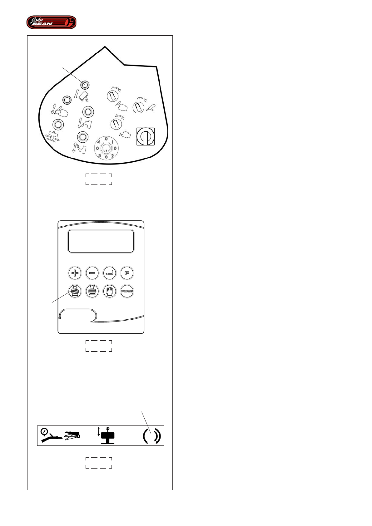
Layout
REMOVING THE LOWER BEAD
Keep the lever (2, Fig.4.1-2) activated to operate the
lower tire removal tool.
2
4.1-2
Then the machine stops automatically as the operator
has to fit the bead onto the tool manually.
Now continue with the last phase where the tire is
removed completely from the rim and the tools and discs
are positioned to start the mounting operations.
The machine emits a beep and the message “MANUAL
MODE” appears again on the display.
At this point the Automatic Demounting Program has
finished.
WARNING:
WHEN THE UNCLAMP RIM PEDAL IS PRESSED ALL
THE ACQUIRED DATA IS DELETED.
4.2.2 Automatic Mounting Program
Having removed the tire, the work cycle can continue
by mounting a new tire.
To proceed with mounting operation you should:
• Select the Automatic Mounting (5, Fig.4.1-1) key.
Within the Automatic Mounting Program the following
Subprograms are run in this order:
- Mounting the lower bead
5
4.1-1
- Mounting the upper bead
MOUNTING THE LOWER BEAD
• Activate the lever (2, Fig.4.1-2).
The tool moves up to the rim. This phase ends with an
initial machine stop.
• Position the tire on the rim.
• Activate the Pedal (3, Fig.4.1-3), to fit the lower bead
onto the rim.
44
4.1-3
Note: Every time the work cycle begins with a Mounting
3
Operator’s Manual QUADRIGA 1000/BB
Program or if the wheel has been unclamped
after the Automatic Demounting Program, the
machine laser scanner scans the entire rim
profile to ascertain the exact positions of the
flanges.
Page 45

Description
Identifikation der einzelnen Teile
DECOLLER LE T ALON INFERIEUR
Si on continue à actionner la manette (2, Fig.4.1-2),
l'outil inférieur entre en fonction pour déjanter le pneu.
Après quoi, on a un arrêt automatique. L'opérateur doit
faire monter à la main le talon sur l'outil.
On arrive maintenant à la dernière phase ; le pneu est
complètement sorti de la jante et les outils et les
disques se placent correctement pour commencer
l'opération de montage.
La machine émet un "bip" et sur l'afficheur apparaît à
nouveau "MODE MANUEL".Le Programme Démontage
Automatique est terminé.
A TTENTION :
A LA PRESSION DE LA PEDALE DE DEBLOCAGE
JANTE, LES DONNEES ACQUISES SERONT
PERDUES.
4.2.2 Programme Montage Automatique
ENTFERNUNG DES UNTEREN WULSTES
Wenn das Bedienelement (2, Abb.4.1-2) weiter betätigt wird,
setzt sich das untere Werkzeug in Betrieb, um den Reifen
zu entfernen.
Nun erfolgt ein automatischer Halt. Der Bediener muss
den Wulst manuell auf das Werkzeug heben.
Nun fährt man mit der letzten Phase fort: Der Reifen ist
ganz aus der Felge ausgetreten und die Werkzeuge und
die Scheiben positionieren sich für den Beginn der Montage.
Die Maschine gibt einen Piepton aus und am Display
erscheint wieder "MANUAL MODE".
Das Programm der automatischen Demontage ist beendet.
ACHTUNG:
WENN MAN DAS PEDAL ZUM ABSPANNEN DER
FELGE DRÜCKT, GEHEN DIE ERFASSTEN DATEN
VERLOREN.
4.2.2 Programm zur automatischen
Montage
Après le démontage, le cycle de travail peut se
poursuivre avec le montage d'un nouveau pneu.
Pour procéder au montage, on doit:
• Sélectionner la touche (5, Fig.4.1-1) Montage
Automatique.
Dans le Programme Montage Automatique, on effectue
les programmes secondaires:
- Montage du talon inférieur
- Montage du talon supérieur
MONT AGE DU TALON INFERIEUR
• Si on actionne la Manette (2, Fig.4.1-2).
L'outil s'approche de la jante. La phase s'achève avec
un premier arrêt.
• Placer le pneu en position sur la jante.
• En actionannt la Pédale (3, Fig.4.1-3), on obtient
l'introduction du talon inférieur dans la jante.
NB: Si le cycle de travail commence avec le
Programme de Montage, ou s'il a été effectué
un déblocage de la roue après le Programme
Démontage Automatique, la machine
effectuera d'abord le balayage laser de tout le
profilé de la jante, pour en acquérir les
positions effectives des bords.
Nach der Demontage kann der Betriebszyklus mit der
Montage eines neuen Reifens fortgeführt werden.
Um mit der Montage fortzufahren, tut man Folgendes:
• Die Taste (5, Abb.4.1-1) Automatische Montage
drücken.
Innerhalb des Programms der automatischen Montage
werden folgende Unterprogramme ausgeführt:
- Montage des unteren Wulstes
- Montage des oberen Wulstes
MONT AGE DES UNTEREN WULSTES
• Wenn man das Bedienelement (2, Abb.4.1-2)
betätigt.
Nähert sich das Werkzeug der Felge. Diese Phase
erfolgt mit einem ersten Stopp.
• Den Reifen in die richtige Position an der Felge
bringen.
• Wenn man das Pedal (3, Abb.4.1-3) betätigt, wird
der untere Wulst in die Felge eingesetzt.
Anmerkung: Falls der Betriebszyklus mit dem
Programm der Montage beginnt oder
falls das Rad nach dem Programm
der automatischen Demontage
abgespannt wurde, erfasst die
Maschine zuerst mit dem Laser das
gesamte Felgenprofil, um die
tatsächlichen Positionen der Hörner
aufzunehmen.
Manuel d’Utilisation QUADRIGA 1000/BBQUADRIGA 1000/BB
Betriebsanleitung
45
Page 46
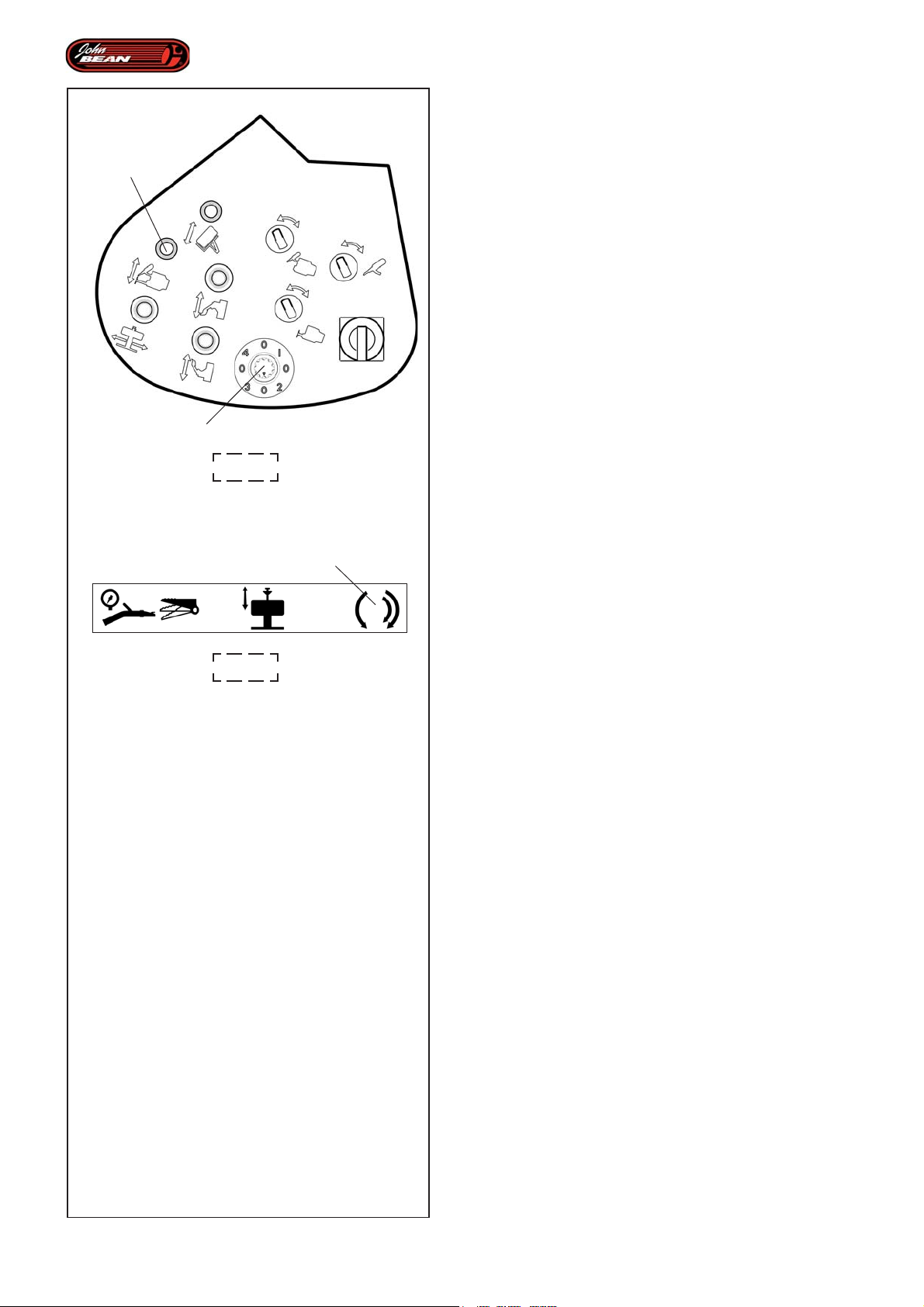
Layout
MOUNTING THE UPPER BEAD
Activate Lever “2” to position the tools on the upper
side of the wheel.
2
The automated cycle stops to allow the operator to
create a space manually on the tire to house the tool.
Lever “2” should then be activated again to position the
tool and the disk on the upper bead.
The machine then stops again (the machine beeps) to
allow the valve in the rim and/or the bead pusher aids
to be positioned.
At this point it is essential that you DO NOT USE the
lever “2” to activate rotation. Instead use the pedal (3,
Fig.4.1-3) to mount the upper bead.
9
4.1-2
3
4.1-3
WARNING:
DO NOT ACTIVATE THE LEVER BEFORE YOU HAVE
COMPLETED THE BEAD INSERTION OPERATION
USING THE PEDAL.
Having removed the bead pusher aids, activate the lever
“2” again to move the tools and bead breaking disks
into the idle position.
The last phase is now finished; the tools and disks are
out of the operating area, the machine beeps and the
“MANUAL MODE” message appears again on the
Display.
The Automatic Mounting Program is now finished, which
means the entire work cycle is finished too.
46
Operator’s Manual QUADRIGA 1000/BB
Page 47

Description
Identifikation der einzelnen Teile
MONT AGE DU TALON SUPERIEUR
Si on actionne la Manette "2", les outils se positionnent
sur la face supérieure de la roue.
L'automatisme s'arrête pour permettre à l'opérateur
d'intervenir manuellement sur le pneu, en produisant
un espace où ira se loger l'outil.
Si on maintient la Manette "2" activée, l'outil et le disque
iront se positionner sur le talon supérieur.
Un ultérieur arrêt aura lieu (on entend un "bip") pour
permettre l'orientation de la soupape de la jante et/ou
le positionnement des outils pour remettre le pneu dans
la jante (presse-talon).
A ce stade, il est fondamental DE NE PAS UTILISER
la Manette "2", mais bien actionner la rotation avec la
pédale (3, Fig.4.1-3) pour obtenir le montage du talon
supérieur.
A TTENTION :
NE PAS ACTIVER LA MANETTE AVANT D'AVOIR
TERMINE LE JANTAGE AVEC LA PEDALE.
Après avoir retiré les outils de jantage, si on actionne
encore la Manette "2", les outils et les disques
détalonneurs vont en position "hors travail".
C'est ainsi que se termine la dernière phase, les outils
et les disques se trouvent en dehors de la zone
opérationnelle, la machine émet un "bip" et sur l'afficheur
apparaît à nouveau "MODE MANUEL".
Le Programme Montage Automatique est terminé et
avec lui tout le Cycle de Travail.
MONTAGE DES OBEREN WULSTES
Wenn man das Bedienelement "2" betätigt,
positionieren sich die Werkzeuge auf der Oberseite des
Rads.
Die Automation hält an, damit der Bediener manuell
am Reifen eingreifen und eine Öffnung herstellen kann,
in die sich das Werkzeug einsetzen kann.
Wenn das Bedienelement "2" weiter aktiviert bleibt,
folgt die Positionierung des Werkzeugs und der Scheibe
am oberen Wulst.
Es erfolgt ein weiterer Halt (man hört einen Piepton),
um die Ausrichtung des Felgenventils und/oder die
Positionierung der Hilfsvorrichtungen zum Einsetzen
des Wulstes (Wulstniederhalter) zu ermöglichen.
Nun ist es ganz wichtig, NICHT das Bedienelement
"2" zu VERWENDEN, sondern die Drehung mit dem
Pedal (3, Abb.4.1-3) zu aktivieren, bis der obere Wulst
montiert ist.
ACHTUNG:
AKTIVIEREN SIE DAS BEDIENELEMENT NICHT
WIEDER, BEVOR DER WULST (DURCH DRÜCKEN
DES PEDALS) VÖLLIG EINGESETZT IST.
Nach Entfernen der Hilfsvorrichtungen zum Einsetzen
des Wulstes betätigt man wieder das Bedienelement
"2". Die Werkzeuge und die Wulstablösscheiben fahren
in die Stellung "außerhalb des Betriebs".
Damit endet die letzte Phase. Die Werkzeuge und die
Scheiben befinden sich außerhalb des Arbeitsbereichs,
die Maschine sendet einen Piepton und am Display
erscheint wieder "MANUAL MODE".
Das Programma der automatischen Montage ist
abgeschlossen und damit auch der gesamte
Betriebszyklus.
Manuel d’Utilisation QUADRIGA 1000/BBQUADRIGA 1000/BB
Betriebsanleitung
47
Page 48
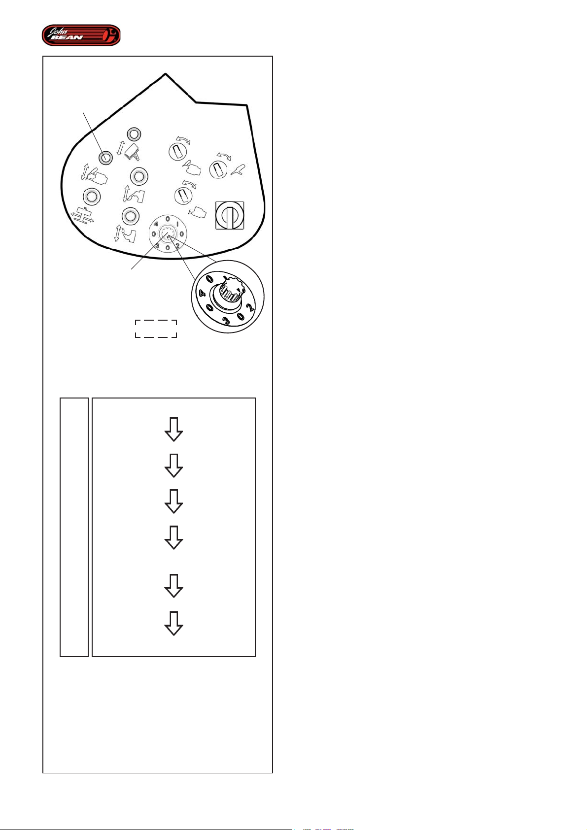
Layout
4.2.3 Selecting an individual Subprogram
2
9
4.1-2
The Mounting and Demounting Programs are made up
of Subprograms and individual specific phases that are
run automatically and always in the same set order.
The purpose of this obligatory sequence is to simplify
the use of the tire changer, to guarantee the acquisition
of fundamental data and to operate in complete safety
in any condition.
Thanks to the operating software installed, the machine
is always informed as to the condition of the tire, in
terms of whether it has been mounted on or demounted
from the rim.
This feature allows the operator to exit the automatic
sequence and choose a subprogram at any time
whatsoever.
The software also manages these operations, so it only
allows the available Subprograms to be selected, i.e.
those that can be run in compliance with the relative
state of the tire and rim.
Note: Any Subprograms that are not running at a
given time are disabled and even if the
corresponding enable selector (9, Fig.4.1-
2) is pressed, this will have no effect
whatsoever.
Fig. 4.2-1
0
1
2
3
0
1
2
Full Tire Remove
Only Bead-break
Only Remove Upper Bead
Only Remove Lower Bead
Full Tire Mount
Mount Lower Bead
Mount Upper Bead
4.2-1
A list of the Selector Functions (9, Fig.4.1-2) in the
Automatic Demounting Program.
Selector Position - Subprogram :
0 - A Complete Tire Demounting Program
Enabled after a wheel has been clamped or at the end
of a Mounting operation.
1 – Bead breaking subprogram
Enabled if steps 2 and 3 have not been performed yet
2 – Upper bead demounting subprogram
Enabled if step 1 has been performed but steps 2 and
3 have not
3 - Lower bead demounting subprogram
Enabled if steps 1 and 2 have not been performed yet
4 – Unused position
A list of the Selector Functions (9, Fig.4.1-2) in the
Automatic Mounting Program.
Selector Position - Subprogram :
0 - A Complete Tire Mounting Program
Enabled after a mounting operation or when a rim has
been clamped.
1 - Lower bead mounting subprogram
Enabled if step 2 has not been performed yet
2 - Upper bead mounting subprogram
Enabled if step 1 has been performed
3 - Unused position
4 - Unused position
48
Operator’s Manual QUADRIGA 1000/BB
Page 49

Description
Identifikation der einzelnen Teile
4.2.3 Sélection d'un Programme Secondaire
Les Programmes de Montage et Démontage, formés
de Programmes Secondaires et de phases spécifiques
individuelles, se suivent automatiquement, toujours
dans le même ordre pré-établi. Cette séquence obligée
a le but de simplifier l'utilisation du démonte-pneu, de
garantir l'acquisition des données fondamentales, ainsi
que d'opérer avec un maximum de sécurité dans
n'importe quelle condition.
Grâce au logiciel de gestion des opérations, la machine
est toujours "consciente" de l'état du pneu, c'est-à-dire
s'il est déjanté ou non.
Cette caractéristique offre à tout moment à l'opérateur
la possibilité de quitter la séquence automatique et de
choisir le Programme Secondaire souhaité.
Le logiciel gère aussi ces opérations, il permet donc
de sélectionner les programmes secondaires,
uniquement ceux possibles, ceux qui peuvent être
exécutés suivant l'état correspondant dans lequel la
jante et le pneu se trouventù.
NB: Les Programmes Secondaires non
exécutables à un moment donné sont
désactivés et leur sélection avec le
sélecteur (9, Fig.4.1-2), ne provoque
aucun effet.
Fig. 4.2-1
Liste des Fonctions du Sélecteur (9, Fig.4.1-2) dans
le Programme Démontage Automatique.
Position du Sélecteur - Programme Secondaire :
0 - Programme Complet de Démontage du
PneuAutorisé après le blocage de la roue ou à la fin du
Montage.
1 - Programme Secondaire de DéjantageAutorisé si 2
et 3 n'ont pas été exécutés
2 - Programme Secondaire de Décollement du talon
supérieurAutorisé si 1 a été exécuté tandis que 2 et 3
n'ont pas été exécutés
3 - Programme Secondaire de Décollement du talon
inférieurAutorisé si 1 et 2 ont été exécutés
4 - Position inutilisée
Liste des Fonctions du Sélecteur (9, Fig.4.1-2) dans
le Programme Automatique de Montage du
Pneumatique.
Position du Sélecteur - Programme secondaire :
0 - Programme Complet de Montage du PneuAutorisé
après le démontage ou le blocage jante.
1 - Programme Secondaire de Montage du talon
inférieurAutorisé si 2 n'a pas déjà été exécuté
2 - Programme Secondaire de Montage du talon
supérieurAutorisé si 1 a déjà été exécuté
3 - Position inutilisée
4 - Position inutilisée
4.2.3 Auswahl eines einzelnen
Unterprogramms
Die Programme zur Montage und Demontage, die aus
Unterprogrammen und aus einzelnen, besonderen
Phasen bestehen, laufen automatisch immer in
derselben, voreingestellten Reihenfolge nacheinander
ab. Diese verbindliche Sequenz hat den Zweck, den
Gebrauch der Reifenmontiermaschine zu vereinfachen,
das Erfassen der wesentlichen Daten zu gewährleisten,
sowie jederzeit in völliger Sicherheit zu arbeiten.
Durch das Programm zur Verwaltung der verschiedenen
Operationen ist der Maschine stets "bewusst", in
welchem Stadium des Entfernens oder Montierens von/
an der Felge der Reifen gerade ist.
Dieses Merkmal bietet dem Bediener jederzeit die
Möglichkeit, die automatische Sequenz zu beenden und
das gewünschte Unterprogramm zu wählen.
Das Programm verwaltet auch diese Operationen, d.h.
es erlaubt nur die Auswahl der möglichen
Unterpogramme, die sich aus dem jeweiligen Zustand
von Felge und Reifen als machbar ergeben.
Anmerkung: Die Unterprogramme, die zu dem
betreffenden Zeitpunkt nicht
ausführbar sind, sind deaktiviert.
Wenn man sie mit dem Wählschalter
(9, Abb. 4.1-2) anwählt, geschieht
nichts.
Abb. 4.2-1
Liste der Funktionen des Wählschalters (9, Abb.4.1-2)
im Programm der automatischen Demontage.
Stellung des Wählschalters - Unterprogramm :
0 - Vollständiges Programm zum Entfernen des
ReifensNach dem Aufspannen des Rads oder am Ende
der Montage erlaubt.
1 - Unterprogramm des Wulstablösens
Erlaubt, wenn 2 und 3 noch nicht ausgeführt wurden.
2 - Unterprogramm zur Demontage des oberen Wulstes
Erlaubt, wenn 1 bereits ausgeführt ist, aber 2 und 3
noch nicht ausgeführt sind.
3 - Unterprogramm zur Demontage des unteren Wulstes
Erlaubt, wenn 1 und 2 bereits ausgeführt sind.
4 - Nicht verwendete Stellung
Liste der Funktionden des Wählschalters (9, Abb.4.1-
2) im Programm der automatischen Montage.
Stellung des Wählschalters - Unterprogramm :
0 - Vollständiges Programm zur Montage des
ReifensNach der Demontage oder dem Aufspannen der
Felge erlaubt.
1 - Unterprogramm zur Montage des unteren
WulstesErlaubt, wenn 2 noch nicht ausgeführt wurde.
2 - Unterprogramm zur Montage des oberen
WulstesErlaubt, wenn 1 bereits ausgeführt wurde.
3 - Nicht verwendete Stellung
4 - Nicht verwendete Stellung
Manuel d’Utilisation QUADRIGA 1000/BBQUADRIGA 1000/BB
Betriebsanleitung
49
Page 50
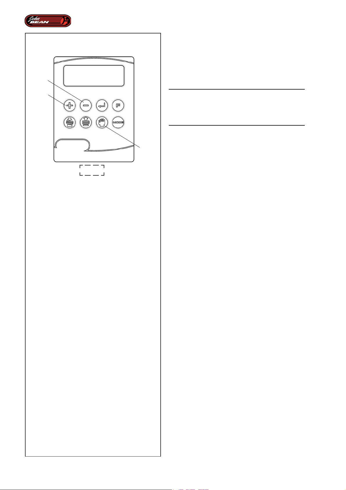
Layout
4.2.4 Expert Choice operating mode
This operating mode allows you to select, at any time,
one of the individual subprograms in the Automatic
Mounting and Demounting Programs.
2
1
7
4.1-1
WARNING:
USING THE EXPERT CHOICE OPERATING MODE IS
RESERVED FOR OPERATORS WITH TRIED AND
TESTED EXPERIENCE AND ADVANCED
KNOWLEDGE OF THE MACHINE.
Sometimes the operator may need to select a given
Subprogram, even if it is not the subprogram that the
Automatic Mode schedules for that particular moment
and even if it is not available in the Individual Subprogram
Selector.
When the machine does not allow a specific
Subprogram to be selected, but the expert operator
foresees the possibility or need to run a certain
operation, he/she can activate the Expert Choice
operating mode.
This situation may occasionally occur, for example:
1- When an individual operation has been unsuccessful:
if the automatic operating phase is completed, the
machine considers the phase to have obtained the
required result, even if it hasn't.
2- When an operation has been performed
independently, i.e. without the intervention of the tire
changer, and if the machine were to perform the
operation again, the wheel or the machine itself might
be seriously damaged.
In both these cases the operator should check that the
relative condition of the rim and tire is not what the
program considers it to be.
The expert operator must be expert enough to be sure
that repeating or skipping the Subprogram in question
will not damage the rim or tire and therefore decide
arbitrarily to use the Expert Choice operating mode.
50
WARNING:
SELECTING EXPERT CHOICE MODE INVOLVES
GREATER RISKS THAN USUAL FOR THE WHEEL
AND MACHINE TOOLS.
To use the Expert Choice operating mode:
The machine must be in Manual Mode, if it is not,
• press the key (7, Fig.4.1-1) to enter manual mode.
• press and hold down the + and – keys
simultaneously (1 and 2, Fig.4.1-1).
This will activate Expert Choice functioning, the
advanced access for Automatic Subprograms.
Operator’s Manual QUADRIGA 1000/BB
Page 51

Description
Identifikation der einzelnen Teile
4.2.4 Fonctionnalité Expert Choice
La fonctionnalité permet de sélectionner à tout moment
un des Programmes Secondaires à l'intérieur des
Programmes Automatiques de Démontage et Montage.
A TTENTION :
L'EMPLOI DE LA FONCTIONNALITE EXPERT CHOICE
EST RESERVE AUX OPERATEURS EXPERIMENTES
ET MAITRISANT PARFAITEMENT L'UTILISATION DE
LA MACHINE.
Parfois, l'opérateur peut avoir la nécessité de sélectionner
un certain Programme Secondaire, indépendamment de
ce que le Mode Automatique prévoit à ce moment donné
et indépendamment de la position du Sélecteur du
Programme secondaire unitaire.
Alors que la machine ne permet pas de sélectionner un
Programme Secondaire spécifique, mais l'opérateur estime
qu'il est possible si ce n'est nécessaire d'effectuer une
certaine opération, il existe une fonctionnalité dénommée
Expert Choice, c'est-à-dire "Le choix de l'expert".
Cette condition peut occasionnellement se présenter par
exemple:
1- Quand une opération ne s'est pas bien terminée ; la
phase opérationnelle automatique s'est donc terminée mais
la machine "estime" que la phase a produit l'effet souhaité.
2- Quand une opération a eu lieu sans l'intervention
spécifique du démonte-pneu ; la machine procéderait à
cette opération ce qui risque d'endommager sérieusement
la roue voire même la machine.
Dans les deux cas, l'opérateur constate que l'état
correspondant dans lequel la jante et le pneu se trouvent
n'est pas celui "considéré" par le programme.
L'opérateur expert est en mesure d'évaluer si la répétition
ou le saut de ce Programme Secondaire peut avoir lieu,
sans provoquer de dommages et décider donc de manière
arbitraire de faire recours à la fonctionnalité Expert Choice.
4.2.4 Expert Choice Funktion
Mit dieser Funktion kann man jederzeit ein einzelnes
Unterprogramm aus den automatischen
Programmen zur Montage und Demontage
auswählen.
ACHTUNG:
DIE ANWENDUNG DER EXPERT CHOICE FUNKTION
IST NUR BEDIENERN MIT GROSSER ERFAHRUNG
UND GUTER KENNTNIS DER MASCHINE ERLAUBT.
Manchmal kann es sein, dass der Bediener ein bestimmtes
Unterprogramm starten muss, unabhängig davon, was die
Automatik gerade vorsieht, und auch davon, was der
Wählschalter für die einzelnen Unterprogramme gerade zur
Verfügung stellt.
Falls die Maschine die Auswahl eines bestimmten
Unterprogramms nicht zulässt, aber der erfahrene Bediener
die Möglichkeit, sowie die Notwendigkeit sieht, eine
bestimmte Operation durchzuführen, gibt es die Funktion
Expert Choice, das heißt "Erfahrene Auswahl".
Diese Bedingungen können hin und wieder auftreten, zum
Beispiel:
1- Wenn eine Einzeloperation nicht erfolgreich abgeschlossen
wurde, aber die Maschine die automatische Arbeitsphase
abgeschlossen hat und in diesem Fall "der Ansicht ist", dass
diese Phase die gewünschte Wirkung gezeigt hat.
2- Wenn eine Operation bereits ohne Anwendung der
Reifenmontiermaschine erfolgt ist. Die Maschine würde diese
Operation noch einmal durchführen, was ein ernsthaftes Risiko
eines Schadens am Rad oder an der Maschine mit sich
bringen würde.
In beiden Fällen stellt der Bediener fest, dass der jeweilige
Zustand der Felge und des Reifens nicht derjenige ist, der
im Programm vorgesehen ist.
Ein erfahrener Bediener ist dazu imstande, einzuschätzen,
ob das betreffende Unterprogramm wiederholt oder
übersprungen werden kann, ohne Schäden zu verursachen,
und kann somit selbstständig entscheiden, die Expert Choice
Funktion anzuwenden
A TTENTION :
LA SELECTION DE LA FONCTIONNALITE EXPERT
CHOICE COMPORTE DES RISQUES MAJEURS
POUR LA ROUE ET LES OUTILS DE LA MACHINE.
Pour activer la fonctionnalité Expert Choice:
la machine doit se trouver dans le Mode Manuel, si ce
n'est pas le cas,
• presser la touche (7, Fig.4.1-1) pour y accéder.
• Presser simultanément pendant quelques secondes
les touches + et - (1 et 2, Fig.4.1-1).
La fonctionnalité Expert Choice pour l'accès avancé aux
Programmes Secondaires Automatiques s'active.
Manuel d’Utilisation QUADRIGA 1000/BBQUADRIGA 1000/BB
ACHTUNG:
DIE ANWAHL DER EXPERT CHOICE FUNKTION BRINGT
GRÖSSERE GEFAHREN FÜR DAS RAD UND DIE
WERKZEUGE DER MASCHINE MIT SICH.
Um die Expert Choice Funktion zu aktivieren, geht man
folgendermaßen vor:
Die Maschine muss sich im Manualbetrieb (Manual Mode)
befinden, falls nicht,
• Drücken Sie die Taste (7, Abb.4.1-1), um diese Betriebsart
zu aktivieren.
• Drücken Sie gleichzeitig einige Sekunden die Tasten +
und - (1 und 2, Abb.4.1-1).
Die Expert Choice Funktion zum fortgeschrittenen Zugang
zu den automatischen Unterprogrammen wird aktiviert.
Betriebsanleitung
51
Page 52
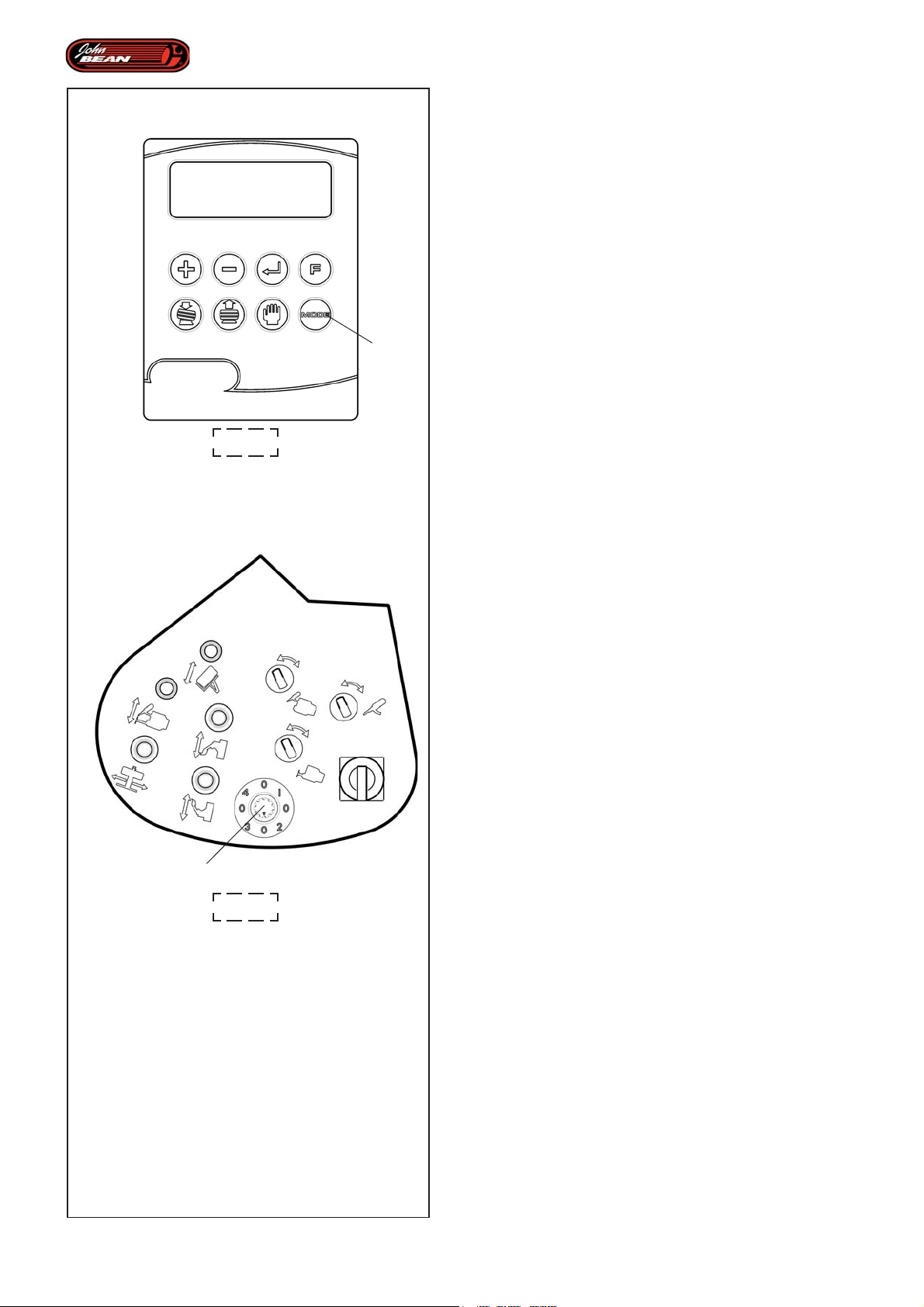
E
Layout
The letter “E” will appear in the top righthand corner of
the display (Fig. 4.1-1).
The operator should now select the Automatic
Demounting or Automatic Mounting Program.
And then select the required Subprogram, using the
relevant selector (9, Fig.4.1-2) (see the Selecting an
Individual Subprogram chapter).
Nota: When the Subprogram selected has been
completed, the machine returns automatically
to Manual Mode.
4.1-1
8
4.2.5 Selecting Wheel Mode
The automatic programs can be adapted to suit a
certain type of wheel by selecting the different
Wheel Modes available in the User Interface.
The size and construction feature of tires may differ
considerably so tire changer operations should be
adapted to individual requirements.
A tire with a particularly low profile, for example, needs
a different procedure to one with a higher side. Small
wheels with a very soft shoulder cannot be
demounted using the same manoeuvres used for
normal or sports tires.
Press key (8, Fig. 4.1-1) to select the Wheel Mode.
Press it again to rotate the tire type selection option
in this order: NORMAL, SPORT, SOFT.
Conditions for selecting the Wheel Mode option:
52
NORMAL
This is for tires with a normal type shoulder regardless
of the wheel diameter or width.
9
4.1-2
SPORT
For all particularly low profile tires (for example /30, /
35). Here, the bead breaking disk pressure should
be lower and the upper bead gripping procedure
should be performed by rotating the wheel in an
anticlockwise direction.
SOFT
For all tires with particularly soft sides (compared to a
Normal Mode procedure, here there are also
differences in the bead breaking and upper bead
extraction subprogram).
Note: At start up the machine always sets NORMAL
mode by default.
Operator’s Manual QUADRIGA 1000/BB
Page 53

Description
Identifikation der einzelnen Teile
La lettre "E" apparaît en haut à droite sur l'afficheur
(Fig. 4.1-1).
L'opérateur effectue maintenant la sélection du
Programme Démontage Automatique ou Montage
Automatique.
Puis il choisit le Programme Secondaire souhaité, avec
le sélecteur (9, Fig.4.1-2) (voir rubrique Sélectionner
un Programme Secondaire).
NB: Une fois le Programme Secondaire sélectionné
terminé, la machine se remet automatiquement
dans le Mode Manuel.
4.2.5 Sélection Mode Roue
Les programmes automatiques peuvent être adaptés
en fonction du type de roue, en sélectionnant parmi
les différents Modes Roue disponibles dans
l'Interface Utilisateur.
Les caractéristiques dimensionnelles et constructives
des pneus peuvent être légèrement différentes, c'est
pourquoi l'opérativité du démonte-pneu doit être
adaptée aux exigences individuelles.
Rechts oben am Display (Fig. 4.1-1) erscheint der
Buchstabe "E".
Nun wählt der Bediener das Programm für die automatische
Demontage oder für die automatische Montage.
Danach wählt er mit dem Wählschalter (9, Abb.4.1-2)
das gewünschte Unterprogramm (siehe das Kapitel
"Auswahl eines einzelnen Unterprogramms").
Nota: Nach Abschluss des gewählten
Unterprogramms stellt sich die Maschine
automatisch auf den Manualbetrieb
(Manual Mode) zurück.
4.2.5 Auswahl des Radmodus
Die automatischen Programme können an den Radtyp
angepasst werden, indem man einen der
verschiedenen Radmodi anwählt, die in der
Bedienerschnittstelle verfügbar sind.
Die Größe und die Baumerkmale der Reifen können
sehr unterschiedlich sein, daher müssen die
Funktionen der Reifenmontiermaschine auf die
jeweiligen besonderen Anforderungen abgestimmt
werden.
Un pneu à profil fortement surbaissé nécessite une
procédure différente d'un pneu dont le profil est plus
haut. Des roues de petites dimensions dont le pneu
présente une épaule très adoucie ne peuvent pas
être déjantées en opérant des manœuvres adaptées
pour des pneus normaux ou sportifs.
La sélection du Mode Roue a lieu avec la touche (8,
Fig. 4.1-1). En pressant plusieurs fois la touche,
on effectue, à rotation, le choix du type de pneu,
dans la séquence NORMAL, SPORT, SOFT.
Conditions dans lesquelles choisir l'option Mode
Roue:
NORMAL
Dans le cas de pneus dont l'épaule présente des
caractéristiques communes, indépendamment du
diamètre et de la largeur de la roue.
SPORT
Pour tous les pneus dont le profil est particulièrement
surbaissé (environ /30, /35). La pression des disques
détalonneurs est inférieure et la procédure
d'accrochage du talon supérieur a lieu avec une
rotation antihoraire de la roue.
Ein sehr niedriger Reifen erfordert zum Beispiel ein ganz
anderes Vorgehen als ein Reifen mit höherer Flanke.
Kleine Räder, die einen Reifen mit einer sehr weichen
Schulter haben, können nicht mit den Operationen
demontiert werden, die sich z.B. für normale oder
Sportreifen eignen.
Die Auswahl des Radmodus erfolgt über die Taste (8,
Abb. 4.1-1). Wenn man die Taste während des
Drehens mehrere Male drückt, erfolgt die Auswahl
des Reifentyps - nacheinander erscheinen NORMAL,
SPORT, SOFT.
Umstände, unter denen man die Option
"Radmodus" wählen sollte:
NORMAL
Bei einem Reifen, dessen Schulter die üblichen
Eigenschaften hat, unabhängig vom Durchmesser
und von der Breite des Rads.
SPORT
Bei allen Reifen mit einer besonders niedrigen Flanke
(ungefähr /30, /35). Der Druck der
Wulstablösscheiben ist niedriger und das Vorgehen
zum Einhaken des oberen Wulstes erfolgt bei
Drehung des Rads gegen den Uhrzeigersinn.
SOFT
Pour tous les pneus dont le profil est particulièrement
tendre (relativement au Mode Normal, cette option
présente des différences dans le Programme
Secondaire de déjantage et décollement du talon
supérieur).
NB: Au démarrage, la machine se met toujours
dans le Mode Roue NORMAL.
Manuel d’Utilisation QUADRIGA 1000/BBQUADRIGA 1000/BB
SOFT
Bei allen Reifen mit einer besonders weichen Flanke
(im Vergleich zum Normalmodus bestehen hier
Unterschiede im Unterprogramm zum Abdrücken und
zum Abziehen des oberen Wulstes).
Anmerkung: Beim Start stellt sich die Maschine
immer auf den Radmodus NORMAL.
Betriebsanleitung
53
Page 54
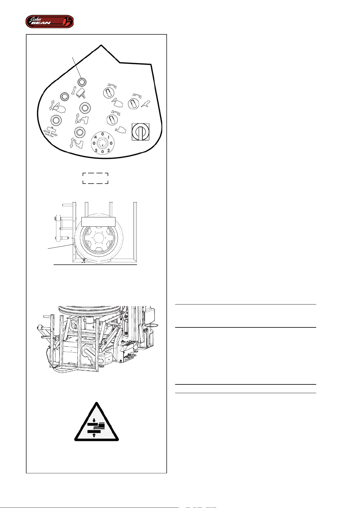
Layout
4.3 Operating Parts
1
Using and checking the MANUAL mode controls.
4.3.1 Wheel Lifter
The lifter is an operating part that the machine is fitted
with. It is designed to load to the Wheel Holder Table
and to return the complete wheels or just the rim to the
ground.
The lifter cannot be used for uses other than lifting/
lowering wheels (or rims) from the Wheel Holder Table.
The lifter has a maximum capacity of 70Kg
Having loaded a wheel with a large enough diameter
and having activated the Wheel Sensor Arm (Fig.4.3-
4.1-2
MAX 70Kg
a
4.3-1
1), proceed as follows:
• Check that the machine is in Manual Mode.
• Activate the lever (1, Fig.4.1-2) and hold it in the
forward position. The machine will beep and the lifter
will begin the automatic wheel load procedure.
Having completed this operation the lifter stops in the
start position on the ground (Fig.4.3-2) and the beeper
stops sounding.
• Release the control lever.
• Activate the lever (1, Fig.4.1-2) and hold it in the
back position. The machine will beep and the lifter
will begin the automatic wheel unload procedure.
Having completed this operation the lifter stops in the
start position and the machine beeps.
• Release the control lever.
4.2-2
4.3-3
WARNING: THESE OPERATIONS MAY BE
DANGEROUS SO OBSERVE THE SAFETY
INSTRUCTIONS SET OUT ON THE PLATES.
Note: The command can be released in any position
and the operation will be interrupted. If the
command is activated again, the operation
will be resumed from wherever it is.
Figure 4.3-3
DANGER OF FEET BEING CRUSHED.
54
Operator’s Manual QUADRIGA 1000/BB
Page 55

Description
Identifikation der einzelnen Teile
4.3 Organes Fonctionnels
Actionnement et contrôle des commandes dans le Mode
MANUEL.
4.3.1 Elévateur roues
L’élévateur est un organe fonctionnel dont la machine est
équipée de série ; cet élément a été conçu exclusivement
pour le levage sur la table porte-roue et le retour au sol
des roues complètes ou de la jante uniquement.
Il est interdit d’utiliser l’élévateur pour un usage autre
que le chargement/déchargement des roues (ou jantes)
de la Table Porte Roues.
L’élévateur a une capacité de charge maximale de 70
kg
Après avoir chargé une roue ayant un diamètre suffisant
à activer le Bras Capteur Roue (Fig.4.3-1), procéder
comme suit:
• Vérifier si la condition Mode Manuel est active.
• Actionner et maintenir la manette (1, Fig.4.1-2) en
avant ; l'avertisseur sonore s'active et l'élévateur
commence la procédure de chargement automatique
de la roue.
L'opération terminée, l'élévateur s'arrête dans la position
de départ au sol (Fig.4.3-2) et l'avertisseur sonore se
désactive.
• Relâcher la commande.
• Actionner et maintenir la manette (1, Fig.4.1-2) en
arrière ; l'avertisseur sonore s'active et l'élévateur
commence la procédure de déchargement
automatique de la roue.
A la fin, l'élévateur s'arrête dans la position de départ et
l'avertisseeur sonore se désactive.
• Relâcher la commande.
4.3 Funktionselemente
Aktivierung und Überprüfung der Steuerungen im
MANUALBETRIEB.
4.3.1 Radheber
Der Radheber ist ein Funktionselement, mit dem die
Maschine serienmäßig ausgestattet ist. Dieses Element
dient ausschließlich dazu, um die vollständigen Räder
oder nur die Felge auf den Radtisch zu laden und wieder
auf der Erde abzusetzen.
Es ist verboten, den Radheber für andere Zwecke als
das Auf-/Abladen der Räder (oder Felgen auf den/vom
Radtisch zu verwenden.
Der Heber hat eine maximale Kapazität von 70 kg.
Nachdem man ein Rad geladen hat, dessen
Durchmesser ausreichend ist, um den Radsensorarm
(Abb.4.3-1) zu starten, geht man folgendermaßen vor:
• Überprüfen, ob die Maschine auf Manualbetrieb
(Manual Mode) geschaltet ist.
• Das Bedienelement (1, Abb.4.1-2) nach vorne
drücken und halten; das akustische Signal wird
aktiviert und die Hebebühne (der Heber) beginnt mit
dem Vorgang zum automatischen Laden des Rads.
Nach Abschluss dieser Operation hält die Hebebühne
in der Ausgangsposition am Boden (Abb.4.3-2) an und
das akustische Signal wird deaktiviert.
• Das Bedienelement loslassen.
• Das Bedienelement (1, Abb.4.1-2) nach hinten
drücken und halten; das akustische Signal wird
aktiviert und die Hebebühne beginnt mit dem Vorgang
zum automatischen Abladen des Rads.
Am Ende hält die Hebebühne in der Ausgangsposition
an und das akustische Signal wird deaktiviert.
• Das Bedienelement loslassen.
A TTENTION : LES MANOEUVRES REPRESENTENT
UN DANGER. RESPECTER LES CONSIGNES DE
SECURITE INDIQUEES PAR LES PLAQUETTES
APPOSEES SUR LA MACHINE.
NB: Il est possible de relâcher la commande
quelle que soit la position ; l'action
s'interrompt.Si on commande à nouveau,
le mouvement reprend dans la position où
il se trouve.
Figure 4.3-3
DANGER D'ECRASEMENT PIEDS.
Manuel d’Utilisation QUADRIGA 1000/BBQUADRIGA 1000/BB
ACHTUNG: DIESE VORGÄNGE SIND GEFÄHRLICH.
BEFOLGEN SIE DIE VORGESCHRIEBENEN
SICHERHEITSMASSNAHMEN, DIE AUF DEN
SCHILDERN ANGEGEBEN SIND
Anmerkung: Es ist möglich, das Steuerelement in jeder
Position loszulassen, dann wird die
Aktivität unterbrochen. Betätigt man
das Element wieder, wird die
Bewegung aus der Position, in der sie
sich befindet, weitergeführt.
Abbildung 4.3-3
QUETSCHGEFAHR FÜR DIE FÜSSE
Betriebsanleitung
55
Page 56
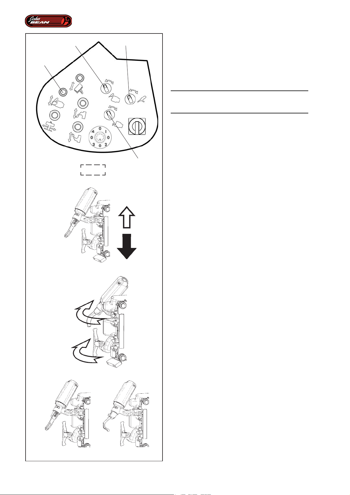
Layout
6
7
2
8
4.1-2
4.3.2 Tool Holder Unit
To use the Tool Holder Unit correctly, proceed as
follows:
• Check that the machine is in Manual Mode.
WARNING: THESE OPERATIONS MAY BE
DANGEROUS SO OBSERVE THE SAFETY
INSTRUCTIONS SET OUT ON THE PLATES.
T ool Holder Unit upstroke:
• Activate the lever (2, Fig.4.1-2) and hold it in the
forward position; the Tool Holder Unit will move
upwards (Fig.4.3-4).
• Release the command when the upper end stop is
reached.
T ool Holder Unit downstroke:
• Activate the lever (2, Fig.4.1-2) and hold it in the
back position; the Tool Holder Unit will move
downwards (Fig.4.3-4).
• Release the command when the lower end stop is
reached.
Note: The command can be released in any position
and the operation will be interrupted. If the
command is activated again, the operation
will be resumed from wherever it is.
Upper Tool Arm Sideways Movement:
• Switch the selector (6, Fig.4.1-2) to the right and
4.3-4
1
2
4.3-5
the upper tool arm will move sideways towards the
outside of the machine (1, Fig.4.3-5).
• Switch the selector (6, Fig.4.1-2) to the left; and
the upper tool will move back inwards to the work
position.
Lower Tool Arm Sideways Movement:
• Switch the selector (8, Fig.4.1-2) to the right and
the lower tool arm will move sideways towards the
outside of the machine (2, Fig.4.3-5).
• Switch the selector (8, Fig.4.1-2) to the left; and
the lower tool will move back inwards to the work
position.
Upper Rotation T ool:
• Switch the selector (7, Fig.4.1-2) to the left; the
upper wheel tool rotates and prepares to be inserted
between the tire and the rim (1, Fig.4.3-6).
• Switch the selector (7, Fig.4.1-2) to the right; the
upper wheel tool rotates and moves to the bead grip
position to extract it from the rim (2, Fig.4.3-6).
56
1
2
4.3-6
Operator’s Manual QUADRIGA 1000/BB
Page 57

Description
Identifikation der einzelnen Teile
4.3.2 Groupe Porte-Outils
Pour commander correctement le Groupe Porte-Outils,
procéder comme suit:
• Vérifier si la condition Mode Manuel est activée.
A TTENTION : LES MANOEUVRES REPRESENTENT
UN DANGER. RESPECTER LES CONSIGNES DE
SECURITE INDIQUEES PAR LES PLAQUETTES
APPOSEES SUR LA MACHINE.
Montée Groupe Porte-Outils:
• Actionner et maintenir la manette (2, Fig.4.1-2) en
avant ; le Groupe Porte-Outils se déplace vers le
haut (Fig.4.3-4).
• Relâcher la commande une fois le fin de course
supérieur atteint.
Descente Groupe Porte-Outils:
• Actionner et maintenir la manette (2, Fig.4.1-2) en
arrière ; le Groupe Porte-Outils se déplace vers le
bas (Fig.4.3-4).
• Relâcher la commande une fois le fin de course
inférieur atteint.
NB: Il est possible de relâcher la commande
quelle que soit la position ; l'action
s'interrompt.Si on commande à nouveau,
le mouvement reprend dans la position où
il se trouve.
Translation Bras Outil Supérieur:
• Actionner le sélecteur (6, Fig.4.1-2) à droite ; le
bras de l'outil supérieur translate vers l'extérieur de
la machine (1, Fig.4.3-5).
• Actionner le sélecteur (6, Fig.4.1-2) à gauche ; l'outil
supérieur retourne vers l'intérieur, en position de
travail.
Translation Bras Outil Inférieur:
• Actionner le sélecteur (8, Fig.4.1-2) à droite ; le
bras de l'outil inférieur translate vers l'extérieur de la
machine (2, Fig.4.3-5).
• Actionner le sélecteur (8, Fig.4.1-2) à gauche ; l'outil
inférieur retourne vers l'intérieur, en position de travail.
Rotation Outil Supérieur:
• Actionner le sélecteur (7, Fig.4.1-2) à gauche; l'outil
supérieur tourne sur lui-même et se prépare à être
introduit entre le pneu et la jante (1, Fig.4.3-6).
• Actionner le sélecteur (7, Fig.4.1-2) à droite ; l'outil
supérieur tourne sur lui-même en position
d'accrochage du talon pour le décoller de la jante
(2, Fig.4.3-6).
4.3.2 Werkzeughaltereinheit
Um die Werkzeughaltereinheit ordnungsgemäß zu
betätigen, geht man folgendermaßen vor:
• Sicherstellen, dass der Manualbetrieb (Manual Mode)
aktiviert ist.
ACHTUNG: DIESE VORGÄNGE SIND GEFÄHRLICH.
BEFOLGEN SIE DIE VORGESCHRIEBENEN
SICHERHEITSMASSNAHMEN, DIE AUF DEN
SCHILDERN ANGEGEBEN SIND
Heben der Werkzeughaltereinheit:
• Das Bedienelement (2, Abb.4.1-2) nach vorne
drücken und halten; die Werkzeughaltereinheit startet
nach oben (Abb.4.3-4).
• Die Steuerung loslassen, wenn der Endschalter oben
erreicht ist.
Senken der Werkzeughaltereinheit:
• Das Bedienelement (2, Abb.4.1-2) nach hinten
drücken und halten; die Werkzeughaltereinheit startet
nach unten (Abb.4.3-4).
• Die Steuerung loslassen, wenn der Endschalter unten
erreicht ist.
Anmerkung: Es ist möglich, das Steuerelement in jeder
Position loszulassen, dann wird die
Aktivität unterbrochen. Betätigt man
das Element wieder, wird die
Bewegung aus der Position, in der sie
sich befindet, weitergeführt.
Verschiebung des oberen Werkzeugarms:
• Den Wählschalter (6, Abb.4.1-2) nach rechts drehen;
der Arm des oberen Werkzeugs verschiebt sich zur
Außenseite der Maschine (1, Abb.4.3-5).
• Den Wählschalter (6, Abb.4.1-2) nach links drehen;
das obere Werkzeug kehrt nach innen in die
Betriebsstellung zurück.
Verschiebung des unteren W erkzeugarms:
• Den Wählschalter (8, Abb.4.1-2) nach rechts drehen;
der Arm des unteren Werkzeugs verschiebt sich zur
Außenseite der Maschine (2, Abb.4.3-5).
• Den Wählschalter (8, Abb.4.1-2) nach links drehen;
das untere Werkzeug kehrt nach innen in die
Betriebsstellung zurück.
Drehung des oberen Werkzeugs:
• Den Wählschalter (7, Abb.4.1-2) nach links drehen;
das obere Werkzeug dreht sich um sich selbst und
bereitet sich darauf vor, zwischen Reifen und Felge
eingesetzt zu werden (1, Abb.4.3-6).
• Den Wählschalter (7, Abb.4.1-2) nach rechts drehen;
das obere Werkzeug dreht sich um sich selbst und
fährt in die Position zum Einhaken des Wulstes, um
ihn von der Felge abzuziehen (2, Abb.4.3-6).
Manuel d’Utilisation QUADRIGA 1000/BBQUADRIGA 1000/BB
Betriebsanleitung
57
Page 58
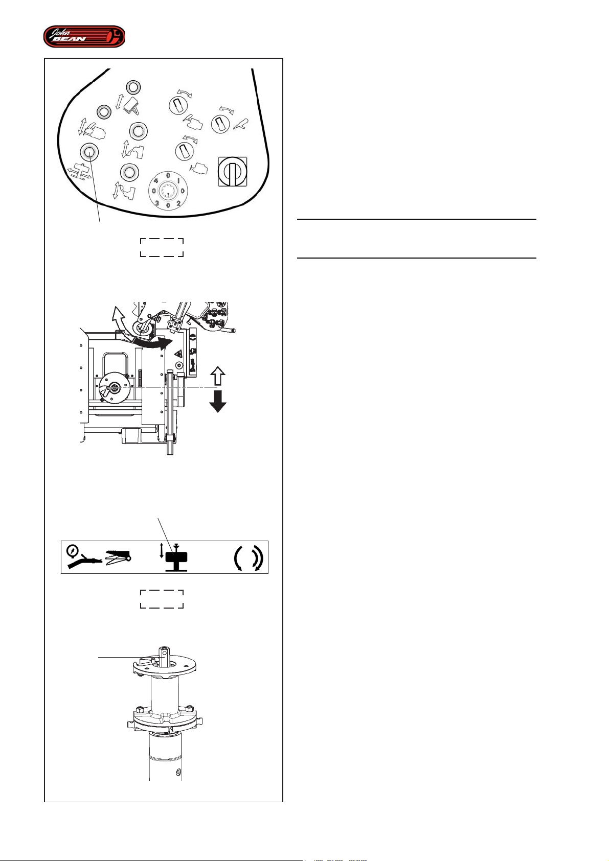
Layout
4.3.3 Wheel Support
The horizontal bead breaking disk wheel near and away
motion requires the Wheel Support to move lengthways
while the bead breaking disk support upright rotates.
The synchronised movement of the parts enables the
disks to operate on the rim border at an optimal level
always.
To use the Wheel Support correctly, proceed as follows::
• Check that the machine is in Manual Mode.
3
4.1-2
4.3-7
2
WARNING: THESE OPERATIONS MAY BE
DANGEROUS SO OBSERVE THE SAFETY
INSTRUCTIONS SET OUT ON THE PLATES.
Move near:
• Activate the lever (3, Fig.4.1-2) to the right and hold
it there. The Wheel Support will move towards the
bead breaking disks (Fig.4.3-7) which will be
positioned according to the movement of the column
that supports them.
• Release the command when the end stop is
reached.
Move away:
• Activate the lever (3, Fig.4.1-2) to the left and hold
it there. The Wheel Support will move away from
the bead breaking disks (Fig.4.3-7), which will move
towards the operator.
• Release the command when the end stop is
reached.
The Wheel Support includes a built-in Wheel Clamping
system powered by a hydraulic circuit and controlled
by the operator pedal.
58
Clamping:
• Press and hold down the pedal (2, Fig.4.1-3) with
your foot. The hexagonal rod (1, Fig.4.3-8) will move
downwards.
4.1-3
• Press and hold down the pedal (2, Fig.4.1-3) with
your foot again. The hexagonal rod (1, Fig.4.3-8)
will move up.
• Release the command when the end stop is
reached.
1
Note: The command can be released in any position
and the operation will be interrupted.
Note: Every time the pedal is pressed, the rod
movement resumes from wherever it is,
but in the opposite direction.
4.3-8
Operator’s Manual QUADRIGA 1000/BB
Page 59

Description
Identifikation der einzelnen Teile
4.3.3 Porte-roue
Le mouvement horizontal d'approche et d'éloignement
de la roue par les disques détalonneurs comporte une
translation longitudinale du Porte-roue et une rotation
simultanée du montant de support des disques
détalonneurs. Le mouvement synchronisé des
composants permet aux disques d'opérer toujours dans
la condition optimale relativement au bord de la jante.
Pour actionner correctement le Porte-roue, procéder
comme suit:
• Vérifier si la condition Mode Manuel est activée.
A TTENTION : LES MANOEUVRES REPRESENTENT
UN DANGER. RESPECTER LES CONSIGNES DE
SECURITE INDIQUEES PAR LES PLAQUETTES
APPOSEES SUR LA MACHINE.
Approche :
• Actionner et maintenir la manette (3, Fig.4.1-2) vers
la droite ; le Porte-roue se déplace dans la direction
des disques détalonneurs (Fig.4.3-7) et ces derniers
s'orientent en suivant le mouvement de la potence
qui les supporte.
• Relâcher la commande une fois le fin de course
atteint.
4.3.3 Radhalterung
Die horizontale Bewegung zur Annäherung und Entfernung
des Rads an die und von den Wulstablösscheiben führt zu
einer Längsverschiebung der Radhalterung und zu einer
gleichzeitigen Drehung des Halterungsständers der
Wulstabslösscheiben. Die synchronisierte Bewegung der Teile
ermöglicht es den Scheiben, immer unter optimalen
Bedingungen in Hinsicht auf das Felgenhorn zu arbeiten.
Um die Radhalterung ordnungsgemäß zu aktivieren, geht
man folgendermaßen vor:
• Sicherstellen, dass der Manualbetrieb (Manual Mode)
aktiviert ist.
ACHTUNG: DIESE VORGÄNGE SIND GEFÄHRLICH.
BEFOLGEN SIE DIE VORGESCHRIEBENEN
SICHERHEITSMASSNAHMEN, DIE AUF DEN SCHILDERN
ANGEGEBEN SIND
Annähern:
• Das Bedienelement (3, Abb.4.1-2) nach rechts drücken
und halten; die Radhalterung startet in Richtung der
Wulstablösscheiben (Abb.4.3-7) und diese richten sich
aus, indem sie der Bewegung ihrer Haltesäule folgen.
• Wenn der Endschalter erreicht ist, das Bedienelement
loslassen.
Eloignement:
• Actionner et maintenir la manette (3, Fig.4.1-2) vers
la gauche ; le Porte-roue s'éloigne des disques
détalonneurs (Fig.4.3-7) , qui se déplacent
simultanément vers l'opérateur.
• Relâcher la commande une fois le fin de course
atteint.
Le système de Blocage Roues est intégré dans le
Porte-roues ; il est assisté d'un circuit hydraulique
et commandé à pédale par l'opérateur.
Blocage:
• Actionner et maintenir avec le pied la pédale (2,
Fig.4.1-3); la tige hexagonale (1, Fig.4.3-8) se
déplace vers le bas.
• Actionner à nouveau et maintenir la pédale avec le
pied (2, Fig.4.1-3) ; la tige hexagonale (1, Fig.4.3-8)
se déplace vers le haut.
• Relâcher la commande une fois le fin de course
atteint.
NB: Il est possible de relâcher la commande
quelle que soit la position ; l'action
s'interrompt.
NB: A chaque actionnement de la pédale, le
mouvement de la tige reprend dans la
position où elle se trouve mais dans la
direction opposée.
Entfernen:
• Das Bedienelement (3, Abb.4.1-2) nach links drücken
und halten; die Radhalterung entfernt sich von den
Wulstablösscheiben (Abb.4.3-7). Diese bewegen sich
gleichzeitig in Richtung des Bedieners.
• Wenn der Endschalter erreicht ist, das Bedienelement
loslassen.
In die Radhalterung ist das Radaufspannsystem integriert,
das durch den Hydraulikkreislauf unterstützt und vom
Bediener mit dem Pedal betrieben wird.
Aufspannen:
• Das Pedal (2, Abb.4.1-3) mit dem Fuß betätigen und
halten; der Sechskantstab (1, Abb.4.3-8) bewegt sich
nach unten.
• Das Pedal (2, Abb.4.1-3) noch einmal mit dem Fuß
betätigen und halten; der Sechskantstab (1, Abb.4.3-8)
bewegt sich nach oben.
• Wenn der Endschalter erreicht ist, das Steuerelement
loslassen.
Anmerkung: Das Steuerelement kann jederzeit losgelassen
werden; die Aktivität wird unterbrochen.
Anmerkung: Bei jeder Betätigung des Pedals wird die
Bewegung des Stabs an der Stelle, an
der er sich befindet, wieder aufgenommen,
aber in der entgegengesetzten Richtung.
Manuel d’Utilisation QUADRIGA 1000/BBQUADRIGA 1000/BB
Betriebsanleitung
59
Page 60
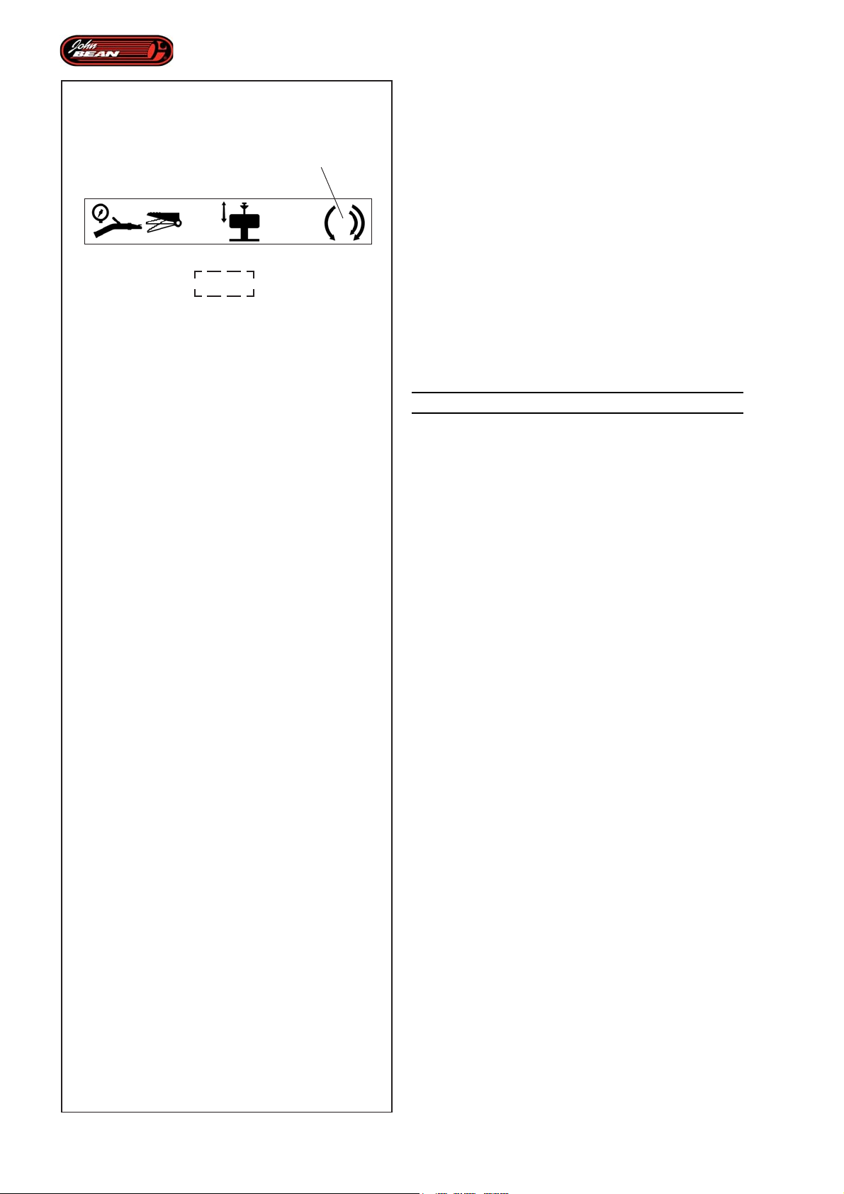
4.1-3
Layout
Rotation:
- Press the pedal (4 Fig.4.1-3) with your foot;
the wheel-holder flange rotates clockwise
as follows.
3
1st speed:
- Press the pedal about 3/4 of the way down, the
turntable rotates at the minimum speed (about 7 rpm).
This is the maximum torque.
2nd speed:
- Press the pedal all the way down, the turntable rotates
at maximum speed (about 14 rpm). This is the reduced
torque.
- From the idle position, raise the pedal, the turntable
rotates anticlockwise.
WARNING: DANGER OF HANDS BEING CRUSHED.
Note: When the machine is in Manual Mode, rotation
is always possible. Whereas in Automatic
Mode rotation is activated by the pedal
and only when the operation in progress
requires it.
During clockwise or anticlockwise rotation operations
in either Manual or Automatic Mode, a safety circuit
may be activated and rotation may be blocked for a few
seconds. This happens if the stress on the product
created by the machine exceed a certain threshold.
If this happens, do not use any controls for the time
the machine software needs to perform an automatic
reset.
60
Operator’s Manual QUADRIGA 1000/BB
Page 61

Description
Identifikation der einzelnen Teile
Rotation :
- Appuyer avec le pied sur la pédale (3,
Fig.4.1-3); la bride porte-roue tourne dans
le sens contraire comme suit.
ère
1
vitesse:
- Appuyer sur la pédale à environ 3/4 ; l'autocentrant
tourne à la vitesse minimale (environ 7 tr/min). Le couple
est maximal.
e
2
vitesse :
- Appuyer sur la pédale à fond; l'autocentrant tourne à
la vitesse maximale (à environ 14 tr/min). Le couple
est réduit.
- De la position de repos, lever le pied de la pédale;
l'autocentrant tourne dans le sens antihoraire.
ATTENTION : DANGER ECRASEMENT MAINS.
NB: Dans le mode Manuel, la rotation est
toujours possible. Dans le mode
Automatique, la rotation commandée par
la pédale est autorisée exclusivement
suivant les nécessités en relation à la
phase opérationnelle courante.
Au cours des opérations de rotation horaire ou
antihoraire, dans le Mode Manuel ou Automatique, un
circuit de protection peut s'activer et provoquer l'arrêt
de la rotation pendant quelques secondes. Ceci se
produit dans le cas où l'effort produit par les usinages
franchit un seuil déterminé.
Dans ce cas, il est nécessaire de n'actionner aucune
commande pendant le temps nécessaire à la
réinitialisation automatique gérée par le logiciel de la
machine.
Drehung:
- Mit dem Fuß das Pedal (3, Abb.4.1-3) drücken; der
Radflansch dreht sich folgendermaßen im
Uhrzeigersinn.
1° Geschwindigkeit:
- Das Pedal um ungefähr ¾ nach unten drücken; das
Spannfutter dreht sich mit der niedrigsten
Geschwindigkeit (ungefähr 7 Umdrehungen/Minute)
mit maximalem Drehmoment.
2° Geschwindigkeit:
- Das Pedal ganz nach unten drücken; das Spannfutter
dreht sich mit Höchstgeschwindigkeit (ungefähr 14
U/min) mit niedrigerem Drehmoment.
- Das Pedal aus der Ruhestellung anheben; das
Spannfutter dreht sich gegen den Uhrzeigersinn.
ACHTUNG: QUETSCHGEFAHR FÜR DIE HÄNDE.
Anmerkung: Im Manualbetrieb ist die Drehung immer
möglich. In den Automatikbetrieben
ist die durch das Pedal angetriebene
Drehung nur in bestimmten Fällen je
nach der aktuellen Arbeitsphase
freigegeben.
Während der Drehung im Uhrzeigersinn oder gegen den
Uhrzeigersinn im Manual- oder im Automatikbetrieb kann
sich ein Schutzkreis aktivieren und dazu führen, dass
die Drehung einige Sekunden gesperrt wird. Dies erfolgt,
falls die durch die Bearbeitungen verursachte Belastung
einen gewissen Schwellwert überschreitet.
In diesem Fall ist es nötig, einige Sekunden lang keinerlei
Steuerelement zu betätigen, bis das
Maschinenprogramm die Maschine automatisch wieder
aktiviert.
Manuel d’Utilisation QUADRIGA 1000/BBQUADRIGA 1000/BB
Betriebsanleitung
61
Page 62
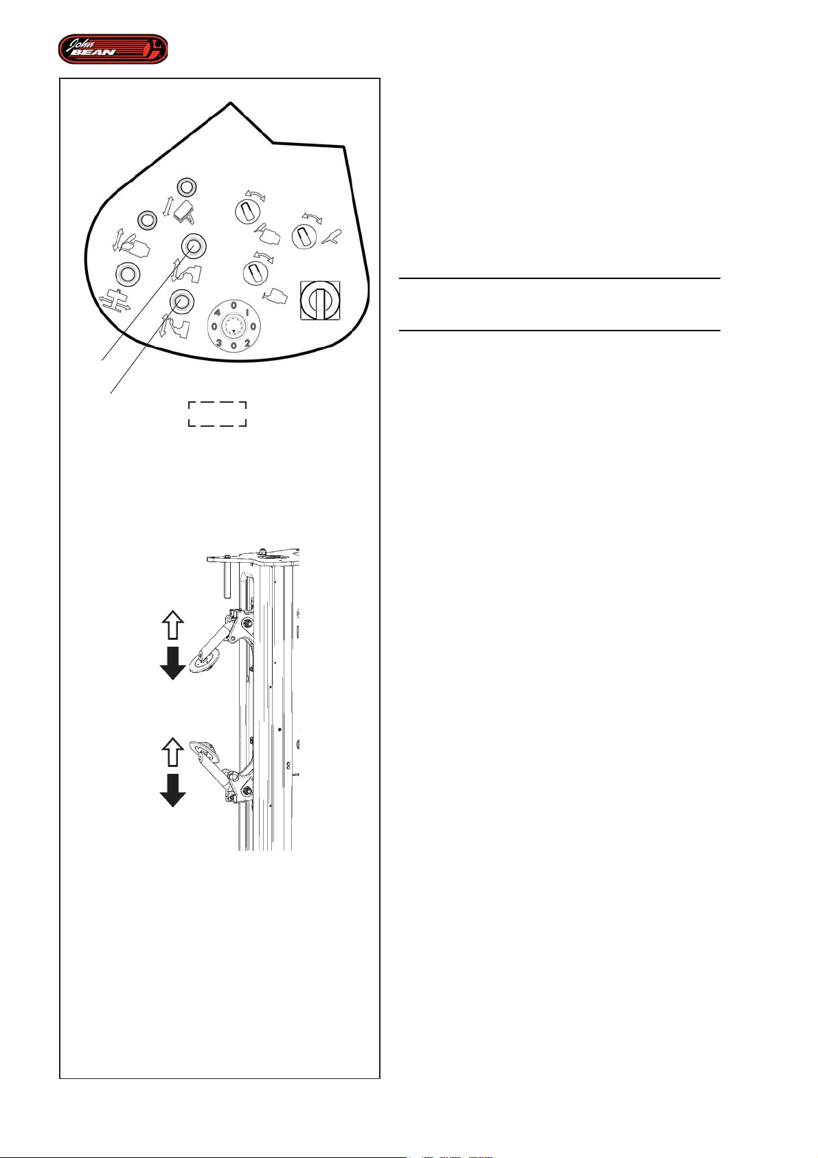
Layout
4.3.4 Bead breaking device
The machine is fitted with an Upper Bead Breaking Disk
and a Lower Bead Breaking Disk, which operate on
the corresponding wheel beads. Both the disk support
arms are fitted with sensors that are required when
operating in AUTOMATIC MODE.
To activate the bead breakers manually, proceed as
follows:
• Check that the machine is in Manual Mode.
WARNING: THESE OPERATIONS MAY BE
DANGEROUS SO OBSERVE THE SAFETY
INSTRUCTIONS SET OUT ON THE PLATES.
4
5
4.1-2
Upper Bead Breaker:
• Activate the lever (4, Fig.4.1-2) and hold it in the
forward position. The Upper Bead Breaker will move
upwards (Fig.4.3-9).
• Activate the lever (4, Fig.4.1-2) and hold it in the
back position. The Upper Bead Breaker will move
downwards (Fig.4.3-9).
• Release the command when the end stop is
reached..
Lower Bead Breaker:
• Activate the lever (5, Fig.4.1-2) and hold it in the
forward position. The Lower Bead Breaker will move
upwards (Fig.4.3-9).
• Activate the lever (4, Fig.4.1-2) and hold it in the
back position. The Lower Bead Breaker will move
downwards (Fig.4.3-9).
• Release the command when the end stop is
reached..
Note: The command can be released in any position
and the operation will be interrupted. If the
command is activated again, the operation
will be resumed from the same position.
62
Nota: The disks must not for any reason come into
contact with each other.
4.3-9
Operator’s Manual QUADRIGA 1000/BB
Page 63

Description
Identifikation der einzelnen Teile
4.3.4 Outil détalonneur
La machine est équipée d'un disque détalonneur
supérieur et un disque détalonneur inférieur, qui opèrent
sur les talons correspondants de la roue. Les deux
bras de support des disques sont équipés de capteurs
nécessaires pour opérer correctement dans le mode
AUTOMATIQUE.
Pour actionner manuellement les outils détalonneurs,
procéder comme suit:
• Vérifier si le Mode Manuel est activé.
A TTENTION : LES MANOEUVRES REPRESENTENT
UN DANGER. RESPECTER LES CONSIGNES DE
SECURITE INDIQUEES PAR LES PLAQUETTES
APPOSEES SUR LA MACHINE.
Outil détalonneur Supérieur:
• Actionner et maintenir la manette (4, Fig.4.1-2) en
avant ; l'outil détalonneur se déplace vers le haut
(Fig.4.3-9).
• Actionner et maintenir la manette (4, Fig.4.1-2) en
arrière ; l'outil détalonneur se déplacer vers le bas
(Fig.4.3-9).
• Relâcher la commande une fois le fin de course
atteint.
4.3.4 Wulstablöser
Die Maschine ist mit einer oberen und mit einer unteren
Wulstablösscheibe ausgestattet, die an den
entsprechenden Wülsten des Rads arbeiten. Beide
Halterungsarme für die Scheiben sind mit den nötigen
Sensoren ausgestattet, um im AUTOMATIKBETRIEB
ordnungsgemäß arbeiten zu können.
Um die Wulstablöser (auch: Abdrückarme) manuell zu
aktivieren, geht man folgendermaßen vor:
• Sicherstellen, dass der Manualbetrieb (Manual Mode)
aktiviert ist.
ACHTUNG: DIESE VORGÄNGE SIND GEFÄHRLICH.
BEFOLGEN SIE DIE VORGESCHRIEBENEN
SICHERHEITSMASSNAHMEN, DIE AUF DEN
SCHILDERN ANGEGEBEN SIND
Oberer Wulstablöser:
• Das Bedienelement (4, Abb.4.1-2) nach vorne
drücken und halten; der obere Wulstablöser bewegt
sich nach oben (Abb.4.3-9).
• Das Bedienelement (4, Abb.4.1-2) nach hinten
drücken und halten; der obere Wulstablöser bewegt
sich nach unten (Abb.4.3-9).
• Die Steuerung loslassen, wenn der Endschalter
erreicht ist.
Outil Détalonneur Inférieur:
• Actionner et maintenir la manette (5, Fig.4.1-2) en
avant ; l'outil détalonneur inférieur se déplace vers
le haut (Fig.4.3-9).
• Actionner et maintenir la manette (4, Fig.4.1-2) en
arrière ; l'outil détalonneur inférieur se déplace vers
le bas (Fig.4.3-9).
• Relâcher la commande une fois le fin de course
atteint.
NB: Il est possible de relâcher la commande
quelle que soit la position ; l'action
s'interrompt.Si on commande à nouveau,
le mouvement reprend dans la position où
il se trouve.
NB: Les disques ne peuvent en aucun cas
entrer en contact.
Unterer Wulstablöser:
• Das Bedienelement (5, Abb.4.1-2) nach vorne
drücken und halten; der untere Wulstablöser bewegt
sich nach oben (Abb.4.3-9).
• Das Bedienelement (4, Abb.4.1-2) nach hinten
drücken und halten; der untere Wulstablöser bewegt
sich nach unten (Abb.4.3-9).
• Die Steuerung loslassen, wenn der Endschalter
erreicht ist.
Anmerkung: Es ist möglich, das Steuerelement in jeder
Position loszulassen, dann wird die
Aktivität unterbrochen. Betätigt man
das Element wieder, wird die
Bewegung aus der Position, in der
sie sich befindet, weitergeführt.
Anmerkung: Die Scheiben dürfen einander auf keinen
Fall jemals berühren.
Manuel d’Utilisation QUADRIGA 1000/BBQUADRIGA 1000/BB
Betriebsanleitung
63
Page 64
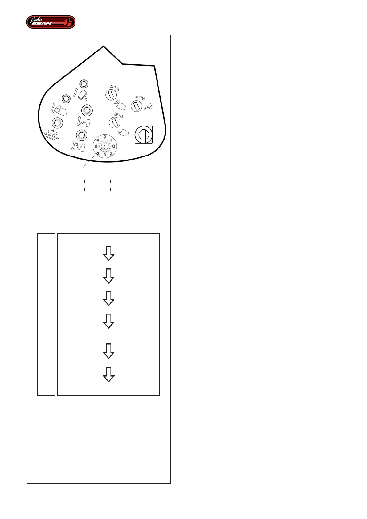
Layout
4.3.5 Individual Automated Parts Selector
Use the selector (9, Fig.4.1-2) on the Control Unit to
select the individual operations (Subprograms) normally
performed in a set order in Automatic Mode running.
Thanks to numerous sensors distributed in specific
points on the machine, the software registers the
workflow continually and is constantly informed as to
the conditions of the various parts involved in the work
cycle. It follows that all this allows a list of possible
operations to be compiled electronically on the basis
of the tasks that have already been completed.
Lastly, the operator can press a certain selector (9,
Fig.4.1-2) to select only the Subprograms that allow
operations to be performed in perfect safety for the
operator, the elements being worked on, (rim and tire)
and the machine itself.
9
4.1-2
Full Tire RemoveFull Tire Remove
0
1
2
3
0
1
2
Full Tire Remove
Full Tire RemoveFull Tire Remove
Only Bead Break
Only Remove Upper
Only Remove Lower
Full Tire MountFull Tire Mount
Full Tire Mount
Full Tire MountFull Tire Mount
Mount Lower Bead
Mount Upper Bead
4.3-10
The diagram (Fig.4.3-10) shows the normal workflow
controlled in Automatic Mode running.
The different selector positions (9, Fig.4.1-2)
correspond to the following functions.
In the Automatic Demounting program:
“Full Tire Remove”:
“0” enables the entire Automatic Demounting cycle.
“Full Tire Remove“.
“1” enables the Automatic BEAD BREAKING
Subprogram,
“Only Bead Break“.
“2” enables the Automatic UPPER BEAD REMOVAL
Subprogram.
“Only Remove Upper“.
“3” enables the Automatic LOWER BEAD REMOVAL
Subprogram.
“Only Remove Lower“.
In the Automatic Mounting program:
“Full Tire Mount Program”:
“0” enables the entire Automatic Mounting cycle.
“Full Tire Mount”.
“1” enables the Automatic LOWER BEAD MOUNT
Subprogram.
“Mount Lower Bead“.
“2” enables the Automatic UPPER BEAD MOUNT
Subprogram.
“Mount Upper Bead“.
64
Operator’s Manual QUADRIGA 1000/BB
Page 65

Description
Identifikation der einzelnen Teile
4.3.5 Sélecteur Automatismes
Avec le sélecteur (9, Fig.4.1-2) situé sur l'Unité de
Commande, il est possible de sélectionner les
opérations (Programmes Secondaires) qui seront
normalement accomplies et en succession dans le
Mode Automatique.
Grâce à de nombreux capteurs installés sur la machine,
le logiciel enregistre continuellement le flux opérationnel
et reconnaît à tout moment les conditions des éléments
en usinage. Tout ceci permet par conséquent de gérer
électroniquement une liste des opérations possibles,
en fonction de celles éventuellement déjà effectuées.
Avec le sélecteur (9, Fig.4.1-2), l'opérateur pourra
sélectionner uniquement les Programmes Secondaires
qui lui permettront d'opérer dans un maximum de
sécurité pour lui, pour les éléments en usinage (jante
et pneu)et pour la machine.
Le schéma (Fig.4.3-10) représente le flux opérationnel
normal réglé par les Modes Automatiques.
Les positions du sélecteur (9, Fig.4.1-2) ont la
fonctionnalité reportée ci-après.
A l'intérieur du programme Démontage Automatique:
“Full Tire Remove”:
“0” permet le cycle entier Démontage Automatique.
“Full Tire Remove“.
“1” autorise le Programme Secondaire Automatique
de DEJANTAGE,
“Only Bead Break“.
“2” autorise le Programme Secondaire Automatique
de DECOLLEMENT TALON SUPERIEUR.
“Only Remove Upper“.
“3” autorise le Programme Secondaire Automatique
de DECOLLEMENT TALON INFERIEUR.
“Only Remove Lower“.
A l'intérieur du programme Montage Automatique :
“Full Tire Mount Program”:
“0” permet tout le cycle Montage Automatique.
“Full Tire Mount”.
“1” autorise le Programme Secondaire Automatique
de MONTAGE TALON INFERIEUR.
“Mount Lower Bead“.
“2” autorise le Programme Secondaire Automatique
de MONTAGE TALON SUPERIEUR.
“Mount Upper Bead“.
4.3.5 Wählschalter für die Automation
Mit dem Wählschalter (9, Abb.4.1-2), der sich auf der
Steuereinheit befindet, kann man einzelne Operationen
(Unterprogramme) anwählen, die normalerweise
innerhalb der automatischen Betriebsarten nacheinander
abgewickelt werden.
Durch die zahlreichen Sensoren, die über die Maschine
verteilt sind, registriert das Programm ständig den
Betriebsfluss und erkennt jederzeit den jeweiligen
Zustand der bearbeiteten Elemente. All dies ermöglicht
es somit, aufgrund der möglicherweise bereits
durchgeführten Operationen elektronisch eine Liste der
möglichen Operationen zu führen. Der Bediener kann
daher mit dem Wählschalter (9, Abb.4.1-2) nur solche
Unterprogramme anwählen, die es erlauben, in völliger
Sicherheit für ihn selbst, für die bearbeiteten Elemente
(Felge und Reifen) und für die Maschine zu arbeiten.
In dem Schema (Abb.4.3-10) ist der normale
Betriebsprozess dargestellt, der durch die
automatischen Betriebsarten geregelt wird.
Die Positionen des Wählschalters (9, Abb.4.1-2) haben
folgende Funktionen.
Im Programm für die automatische Demontage:
“Full Tire Remove”:
"0" ermöglicht den gesamten Zyklus der
automatischen Demontage,
“Full Tire Remove“.
“1” aktiviert das automatische Unterprogramm des
WULSTABLÖSENS,
“Only Bead Break“.
“2” aktiviert das automatische Unterprogramm zur
ENTFERNUNG DES OBEREN WULSTES,
“Only Remove Upper“.
“3” aktiviert das automatische Unterprogramm zur
ENTFERNUNG DES UNTEREN WULSTES,
“Only Remove Lower“.
Im Programm für die automatische Montage:
“Full Tire Mount Program”:
“0” ermöglicht den gesamten Zyklus der
automatischen Montage,
“Full Tire Mount”.
“1” aktiviert das automatische Unterprogramm zur
MONTAGE DES UNTEREN WULSTES,
“Mount Lower Bead“.
“2” aktiviert das automatische Unterprogramm zur
MONTAGE DES OBEREN WULSTES,
“Mount Upper Bead“.
Manuel d’Utilisation QUADRIGA 1000/BBQUADRIGA 1000/BB
Betriebsanleitung
65
Page 66
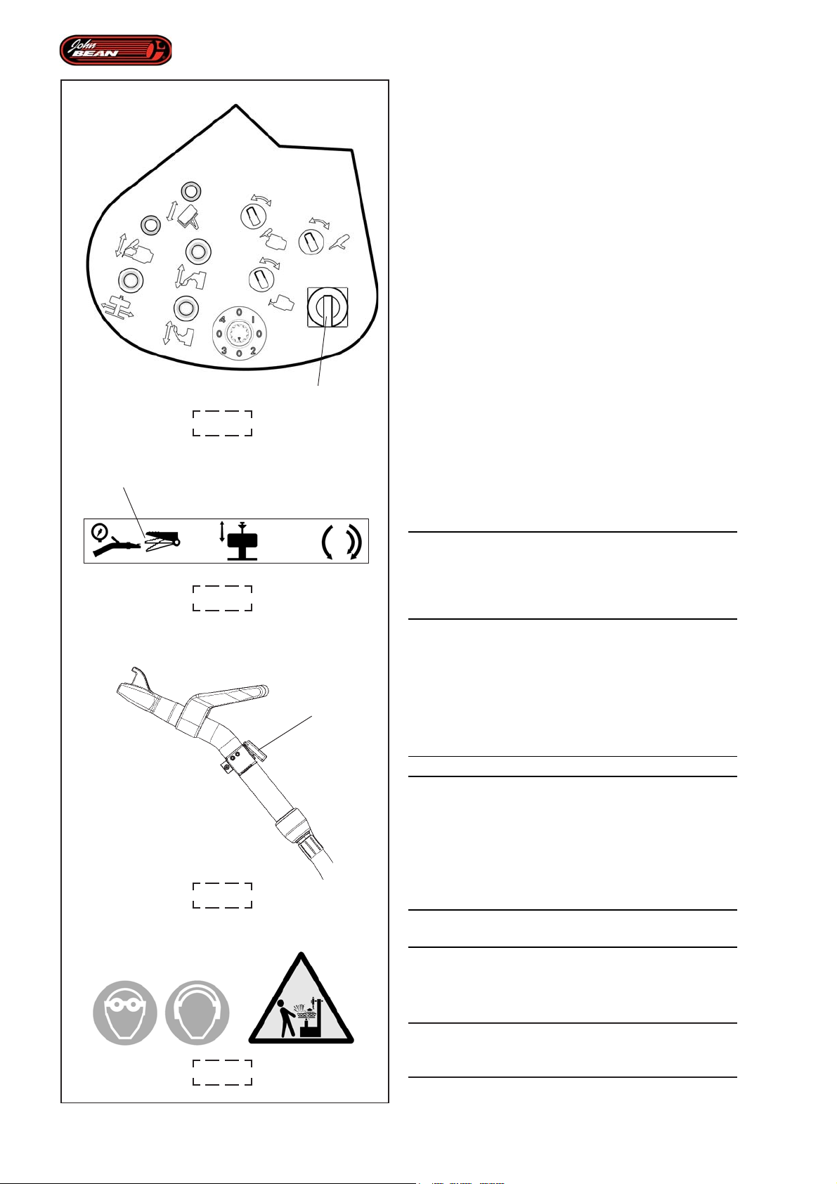
4.1-2
10
Layout
4.3.6 Main ON/OFF Switch
The Main ON/OFF Switch (10, Fig.4.1-2) controls the
electrical power supply to the Tire Changer.
T urn ON:
• Turn the main switch (10, Fig.4.1-2) clockwise to
the “I” position. The tire changer will come on and
the sound of the Hydraulic Control Unit motor can
be heard.
T urn OFF:
• Turn the main switch (10, Fig.4.1-2) anti-clockwise
to the “0” position. The tire changer will stop and
the User Interface display will switch off.
Note: We suggest the operator turns the Main
Switch OFF every time they finish their
work shift.
1
4.3.7 Tubeless Beading System
WARNING: WHEN OPERATING THE BEADING
DEVICE IT IS MANDATORY TO WEAR EAR
PROTECTORS AND SAFETY GLASSES TO
4.1-3
4
PREVENT CONTAMINATION FROM NOISE, DUST
AND CHIPS BLOWN BY THE AIR JET.
Figure 4.1-3
Press the pedal (2 Fig.4.1-3) partially with your RIGHT
foot (1 Fig.4.1-3); the air exits from the end of the hose
previously connected to the tire valve.
Figure 4.1-7
WARNING: DANGER OF TIRE EXPLOSION
Press the key on the Tubeless Beading Nozzle (4,
Fig.4.1-6), then press the pedal all the way down
decisively (1, Fig.4.1-3); a high pressure air jet exits
the Tubeless Beading device.
66
4.1-6
4.1-7
WARNING: HOLD THE TUBELESS BEADING NOZZLE
FIRMLY.
Note: Air simultaneously continues to exit the hose
connected to the tire.
WARNING:
ONCE BEADING IS COMPLETE, IMMEDIATELY
STOP INTRODUCING AIR.
Operator’s Manual QUADRIGA 1000/BB
Page 67

Description
Identifikation der einzelnen Teile
4.3.6 Interrupteur Général
Avec le sectionneur (10, Fig.4.1-2), on gère
l'alimentation électrique du démonte-pneu.
Démarrage :
• Tourner le sectionneur (10, Fig.4.1-2) dans le sens
horaire sur la position "I"; le démonte-pneu démarre,
on entend le son du moteur Centrale Hydraulique.
Mise hors tension:
• Tourner le sectionneur (10, Fig.4.1-2) dans le sens
antihoraire sur la position "0"; le démonte-pneu
s'arrête, l'afficheur de l'Interface Utilisateur s'éteint.
NB: Il est recommandé à l'opérateur d'éteindre
l'interrupteur général chaque fois qu'il
termine sa journée de travail.
4.3.7 Système d'Enjantage Tubeless
4.3.6 Hauptschalter
Mit dem Trennschalter (10, Abb.4.1-2) wird die
Stromversorgung der Reifenmontiermaschine gesteuert.
Start:
• Den Trennschalter (10, Abb.4.1-2) im Uhrzeigersinn
in die Stellung "I" drehen; die Reifenmontiermaschine
startet und man hört das Geräusch des Motors der
Steuerzentrale für die Hydraulik.
Abschalten:
• Den Trennschalter (10, Abb.4.1-2) gegen den
Uhrzeigersinn in die Stellung "0" drehen; die
Reifenmontiermaschine hält an und das Display der
Bedienerschnittstelle schaltet sich ab.
Anmerkung: Es ist ratsam, dass der Bediener die
Maschine jedes Mal, wenn er seine
Arbeitsschicht beendet hat, mit dem
Hauptschalter abschaltet.
4.3.7 Wulsteindrücksystem
ATTENTION : PENDANT L'ACTIONNEMENT DU
DISPOSITIF D’ENJANTAGE, LE PORT
D'EQUIPEMENTS DE PROTECTION DES YEUX ET
DES OREILLES EST OBLIGATOIRE, LE JET D'AIR
POUVANT PROJETER IMPURETES ET
POUSSIERES.
Figure 4.1-3
Appuyer légèrement sur la pédale avec le pied DROIT
(1 Fig.4.1-3); l'air s'échappe par l'extrémité du tuyau
relié à la soupape de la roue.
Figure 4.1-7
ATTENTION: RISQUE D'EXPLOSION DU PNEU
Presser la touche présente sur la Buse d’enjantage
Tubeless (4, Fig.4.1-6), puis presser à fond avec
décision la pédale (1, Fig.4.1-3); un jet d'air à haute
pression sort du dispositif d’enjantage Tubeless.
ATTENTION: MAINTENIR FERMEMENT LA BUSE
D’ENJANTAGE TUBELESS.
ACHTUNG: WÄHREND DIE
WULSTEINDRÜCKVORRICHTUNG BETÄTIGT WIRD, IST
ES PFLICHT, EINEN GEHÖRSCHUTZ UND EINE
SCHUTZBRILLE ZU TRAGEN, UM DAS EINDRINGEN VON
STAUB UND UNREINHEITEN, DIE VOM LUFTSTOSS
AUFGEWIRBELT WERDEN, ZU VERMEIDEN.
Abbildung 4.1-3
- Das Pedal (1, Abb.4.1-3) teilweise mit dem RECHTEN
Fuß drücken; die Luft tritt aus dem Ende des Schlauchs
aus, der vorher an das Radventil angeschlossen wurde.
Abbildung 4.1-7
ACHTUNG:
GEFAHR: REIFEN KÖNNTE EXPLODIEREN.
- Die Taste an der Wulsteindrückdüse für schlauchlose
Reifen (4, Abb.4.1-6) drücken und dann das Pedal (1,
Abb. 4.1-3) fest bis nach unten durchtreten; ein Luftstoß
tritt mit hohem Druck aus der Vorrichtung zum
Wulsteindrücken für schlauchlose Reifen aus.
ACHTUNG: HALTEN SIE DIE WULSTEINDRÜCKDÜSE
SEHR FEST.
Remarque : Simultanément, de l'air continuera à sortir
aussi du tuyau relié à la roue.
A TTENTION:
L’ENJANTAGE TERMINE, ARRETER IMMEDIATEMENT
LE JET D’AIR.
Manuel d’Utilisation QUADRIGA 1000/BBQUADRIGA 1000/BB
Anmerkung: Gleichzeitig tritt auch weiterhin Luft aus
dem Füllschlauch aus.
ACHTUNG:
NACH DEM WULSTEINDRÜCKEN SOFORT DEN
LUFTAUSSTOSS STOPPEN.
Betriebsanleitung
67
Page 68
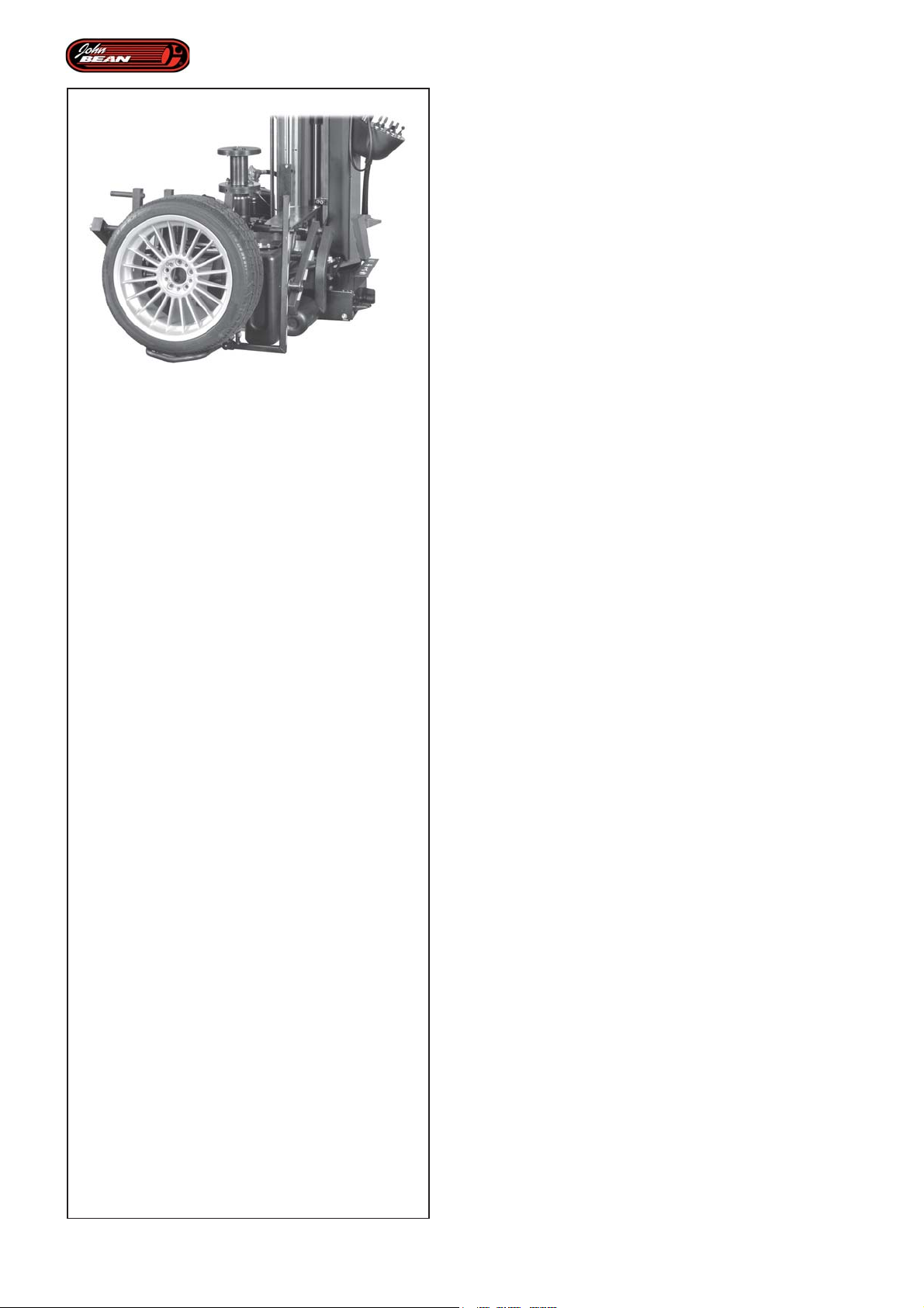
Operations
5.0 Operations
- General precautions
The Super Automatic tire changer is designed for use
with the wheels mentioned previously. It operates
according to preset parameters that guarantee the
smooth running and perfect repeatability of all operations.
For the operations to be perfectly successful the operator
must set the data correctly and supervise the entire
work cycle.
Automatic operation is therefore the main feature of the
tire changer and even if it is possible to mount or
demount the tires in manual mode, the machine
guarantees maximum success only if the Automatic
Mode is used.
WARNING:
USING THE MACHINE IN "MANUAL MODE" OR
INCORRECTLY MAY DAMAGE THE TIRES, RIMS
AND THE MACHINE ITSELF.
WARNING:
USING THE MACHINE IN "MANUAL MODE"
MEANS THAT THE OPERATOR MUST TAKE FULL
RESPONSIBILITY FOR ALL OPERATIONS.
CAUTION:
BEFORE MOUNTING A TIRE ON A RIM ENSURE
THE FOLLOWING RULES ARE OBSERVED:
A- THE RIM MUST BE CLEAN AND IN GOOD
CONDITION: IF NECESSARY CLEAN AFTER
REMOVING ALL WHEEL-WEIGHTS INCLUDING
'TAPE WEIGHTS' INSIDE THE RIM.
B- THE TIRE MUST BE CLEAN AND DRY, WITH
NO DAMAGE TO THE BEAD AND THE CASING.
C- REPLACE THE RUBBER VALVE STEM WITH A
NEW ONE OR REPLACE THE 'O' RING IF THE
VALVE STEM IS MADE OF METAL.
D- LUBRICATION IS NECESSARY FOR CORRECT
MOUNTING OF THE TIRE AND PROPER
CENTERING. USE ONLY AN APPROVED
LUBRICANT FOR TIRES.
68
E- MAKE SURE THE TIRE IS THE CORRECT SIZE
FOR THE RIM.
Operator’s Manual
QUADRIGA 1000/BB
Page 69

Opérativité
Betrieb
5.0 Opérativité
- précautions générales
Le démonte-pneu Super Automatique intervient sur les
roues précédemment citées, en fonction des paramètres
programmés, ce qui lui garantit une continuité et une
reproductibilité parfaite des opérations.
Dans le but de tirer un maximum profit des opérations,
il est demandé à l'utilisateur de paramétrer correctement
les données et de superviser le flux opérationnel.
Le Mode Automatique est donc la caractéristique
fondamentale du démonte-pneu et bien qu'il soit possible
d'effectuer le montage et le démontage des pneus dans
le Mode Manuel, avec la fonctionnalité Automatique,
les résultats sont garantis au maximum.
ATTENTION :
L'UTILISATION DE LA MACHINE DANS LE "MODE
MANUEL" ET DES MANOEUVRES
INOPPORTUNES POURRAIENT PROVOQUER
DES DOMMAGES AUX PNEUS, AUX JANTES
VOIRE MEME A LA MACHINE.
ATTENTION :
L'EMPLOI DE LA MACHINE DANS LE "MODE
MANUEL" EST ENTIEREMENT SOUS LA
RESPONSABILITE DE L'OPERATEUR.
5.0 Vorsichtsmassnahmen bei
Betrieb
Die automatische Reifenmontiermaschine dient dazu,
an den obengenannten Rädern zu arbeiten. Dabei
werden voreingestellte Parameter verwendet, welche die
Flüssigkeit und perfekte Wiederholbarkeit der jeweiligen
Tätigkeiten gewährleisten.
Damit diese Tätigkeiten erfolgreich sind, muss der
Benutzer die Daten ordnungsgemäß einstellen, sowie
den Betriebsfluss überwachen.
Das wesentliche Merkmal der Reifenmontiermaschine
ist der Automatikbetrieb und - obwohl es möglich ist,
die Reifen im Manualbetrieb zu montieren und zu
demontieren - gibt der Automatikbetrieb die
Höchstgarantie für gute Ergebnisse.
ACHTUNG:
DIE ANWENDUNG DER MASCHINE IM
"MANUALBETRIEB" UND UNGEEIGNETE
MANÖVER KÖNNEN ZU SCHÄDEN AN DEN
REIFEN UND DEN FELGEN, SOWIE AN DER
MASCHINE SELBST FÜHREN.
ACHTUNG:
DIE ANWENDUNG DER MASCHINE IM
"MANUALBETRIEB" GESCHIEHT AUF ALLEINIGE
VERANTWORTUNG DES BEDIENERS.
A TTENTION:
AVANT DE MONTER UN PNEU SUR UNE JANTE
SUIVRE LES INDICATIONS SUIVANTES:
A- LA JANTE DOIT ÊTRE PROPRE ET EN BON
ETAT: SI NÉCESSAIRE, LA NETTOYER APRÈS
AVOIR ENLEVÉ TOUTES LES MASSES Y
COMPRIS LES MASSES COLLÉES
ÉVENTUELLEMENT APPLIQUÉES À L'INTÉRIEUR
DE LA JANTE.
B- LE PNEU DOIT ÊTRE PROPRE ET SEC ET NI
LE TALON NI LA CARCASSE NE DOIVENT ÊTRE
ENDOMMAGÉS.
C- REMPLACER LA VANNE EN CAOUTCHOUC
AVEC UNE VANNE NEUVE ET REMPLACER LE
JOINT TORIQUE SI LA VANNE EST EN MÉTAL.
D- LA LUBRIFICATION EST NÉCESSAIRE POUR
MONTER CORRECTEMENT LE PNEU ET
OBTENIR UN CENTRAGE CORRECT DE
L'ENVELOPPE. UTILISER SEULEMENT UN
LUBRIFIANT SPÉCIFIQUE POUR PNEUS.
E- VÉRIFIER SI LE PNEU EST DE LA JUSTE
DIMENSION POUR LA JANTE.
ACHTUNG:
VOR DER REIFENMONTAGE FOLGENDE
VORSICHTMASSREGELN BEACHTEN:
A- DIE FELGE MUSS SAUBER UND IN GUTEM
ZUSTAND SEIN: FALLS NÖTIG, DIE FELGE
REINIGEN, NACHDEM ALLE ALTEN
AUSGLEICHSGEWICHTE, AUCH DIE
KLEBEGEWICHTE AUF DER
FELGENINNENSEITE, ENTFERNT WURDEN.
B- DER REIFEN MUß SAUBER UND TROCKEN
SEIN, WEDER REIFENWULST NOCH
REIFENMANTEL DÜRFEN BESCHÄDIGUNGEN
AUFWEISEN.
C- DAS GUMMIVENTIL DURCH EIN NEUES
ERSETZEN ODER BEI METALLVENTILEN DEN
DICHTRING AUSWECHSELN.
D- FÜR EINE KORREKTE REIFENMONTAGE UND
REIFENZENTRIERUNG AUF
DER FELGE IST EINE AUSREICHENDE
SCHMIERUNG UNBEDINGT
NOTWENDIG. DAZU AUSSCHLIESSLICH
EIN SPEZIELLES REIFENSCHMIERMITTEL
VERWENDEN.
Manuel d’Utilisation QUADRIGA 1000/BBQUADRIGA 1000/BB
E- SICHERSTELLEN, DASS DER REIFEN VON
DEN MASSEN HER ZUR FELGE PASST.
Betriebsanleitung
69
Page 70
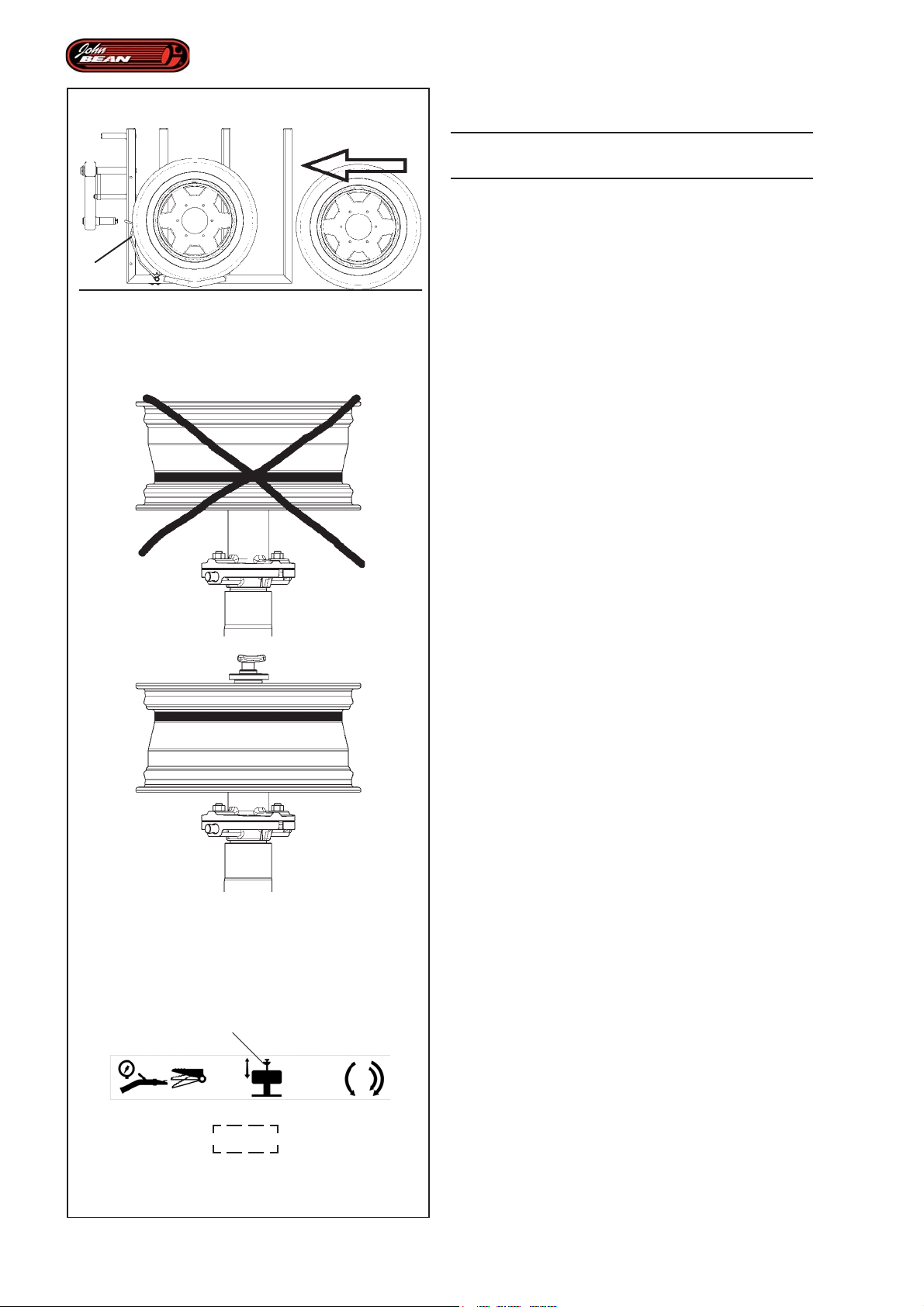
Operations
5.1 Wheel Lifter
WARNING: IF THE WHEELS ARE HEAVY USE THE
LIFT DEVICE
5.1.1 Using the Wheel Lifter
1
Should the user require it, the machine is provided with
5.1-1
a lift device that will raise the wheel or just the rim from
the ground to a suitable working height.
This will prevent any excessive effort or potentially
harmful movements on the part of the operator.
Figure 5.1.1-2
WARNING:
ONCE THE WHEEL HAS BEEN MOUNTED ON THE
FLANGE, THE RIM DROP CENTER MUST ALWAYS
BE POSITIONED HIGH, NEXT TO THE MOUNT/
DEMOUNT TOOL.
5.1-2
OK
5.1.1.1 Loading the wheel
To position the wheel on the front lifter, proceed as
follows:
• Check that the wheel holder flange is free.
• Position the grip pin arm in the closed position
(towards the centre of the flange).
• Check that MANUAL Mode is selected.
• Activate the command (2, Fig. 4.1-3) to move the
rim clamping rod into the right back position.
• Move the wheel up to the front lifter so that the rim
drop center is facing the outside of the machine.
• Load the wheel by rolling it onto the lift device (Fig.
5.1.1-1).
If the wheel positioned on the lift device has an external
diameter that is large enough to activate the Wheel
Sensor Arm (1, Fig. 5.1.1-1), the Load wheel onto Wheel
Holder Flange operation will be enabled and the
movement will be performed automatically by the
machine.
70
2
4.1-3
Note: Wheels with small diameters or rims only
have a low weight and as a result of their
size they may not activate the Wheel
Sensor Arm (1, Fig. 5.1.1-1). So these
parts should be located manually on the
tire changer wheel holder flange.
Operator’s Manual
QUADRIGA 1000/BB
Page 71

Opérativité
Betrieb
5.1 Elévateur Roue
ATTENTION: DANS LE CAS DE ROUES LOURDES,
UTILISER L'ELEVATEUR PREVU A CET EFFET
5.1.1 Utiliser l'élévateur roue
Dans le cas où l'opérateur a l'intention de s'en servir, la
machine est équipée d'un élévateur permettant de
soulever la roue ou uniquement la jante du sol en
position de travail.
Tout effort involontaire et potentiellement dangereux pour
la santé peut être de cette façon évité.
Figure 5.1.1-2
A TTENTION:
UNE FOIS LA ROUE MONTEE SUR LA BRIDE, LE
CREUX DE LA JANTE DOIT TOUJOURS ETRE
TOURNE VERS LE HAUT, PRES DE L'OUTIL DE
DEMONTAGE/MONTAGE.
5.1 Radheber
ACHTUNG: BEI SCHWEREN RÄDERN IST DIE DAFÜR
VORGESEHENE HEBEBÜHNE ZU VERWENDEN
5.1.1 Anwendung des Radhebers
Die Maschine ist mit einer Hebebühne ausgestattet,
die dazu dient, das Rad oder nur die Felge vom Boden
in die Betriebsstellung zu bringen.
Auf diese Weise können unerwünschte und potenziell
gesundheitsgefährdende Belastungen für den Bediener
vermieden werden.
Abbildung 5.1.1-2
ACHTUNG:
SOBALD DAS RAD AM FLANSCH MONTIERT IST,
MUSS DAS FELGENBETT IMMER NACH OBEN
ZEIGEN UND IN DER NÄHE DES MONTAGE-/
DEMONTAGEWERKZEUGS SEIN.
5.1.1.1 Chargement Roue
Pour placer la roue sur l'élévateur avant, procéder comme
suit:
• Vérifier si la bride porte-roue n'est pas engagée.
• Placer le bras de l'axe d'accrochage en position
fermée (vers le milieu de la bride).
• Vérifier si le Mode MANUEL est sélectionné.
• Actionner la commande (2, Fig. 4.1-3) pour conduire
la tige de blocage jante en position de totale
rétraction.
• Approcher la roue de l'élévateur frontal et la tourner
de manière à ce que la jante se trouve vers l'extérieur
de la machine.
• Faire rouler la roue et la charger sur l'élévateur (Fig.
5.1.1-1).
Si la roue placée sur l'élévateur a un diamètre externe
qui suffit à activer le Bras Capteur Roue (1, Fig. 5.1.1-
1), la fonctionnalité de Chargement de la roue sur la
Bride Porte Roue sera autorisée et le mouvement sera
effectué automatiquement par la machine.
5.1.1.1 Das Rad aufladen
Um das Rad am vorderen Heber zu positionieren, geht
man folgendermaßen vor:
• Sicherstellen, dass der Radhalterflansch frei ist.
• Den Arm des Einhakstifts in die geschlossene
Stellung (zur Flanschmitte) bringen.
• Sicherstellen, dass der MANUALBETRIEB
eingestellt ist.
• Das Steuerelement (2, Abb. 4.1-3) betätigen, bis
der Aufspannstab für die Felge ganz zurückgezogen
ist.
• Das Rad an den vorderen Heber annähern und so
ausrichten, dass das Felgenbett zur Außenseite der
Maschine zeigt.
• Das Rad auf die Hebebühne rollen (Abb. 5.1.1-1).
Wenn der Außendurchmessers des Rads, das sich auf
der Hebebühne befindet, groß genug ist, um den
Radsensorarm (1, Abb. 5.1.1-1) zu aktivieren, wird die
Funktion des Ladens des Rads auf den Radhalterflansch
aktiviert und die Maschine führt diese Bewegung
automatisch aus.
NB: Les roues de petit diamètre, ou rien que la
jante, sont des éléments qui pèsent peu ;
étant donné leurs dimensions, ils peuvent
ne pas activer le Bras Capteur Roue (1,
Fig. 5.1.1-1). Ces éléments doivent être
placés à la main sur la bride porte-roue du
démonte-pneu.
Manuel d’Utilisation QUADRIGA 1000/BBQUADRIGA 1000/BB
Anmerkung: Räder mit kleinem Durchmesser oder
bloße Felgen haben ein geringes
Gewicht und es kann sein, dass sie,
aufgrund der Abmessungen, den
Radsensorarm (1, Abb. 5.1.1-1) nicht
aktivieren. Solche Teile müssen
manuell am Radhalterflansch der
Reifenmontiermaschine angebracht
werden.
Betriebsanleitung
71
Page 72
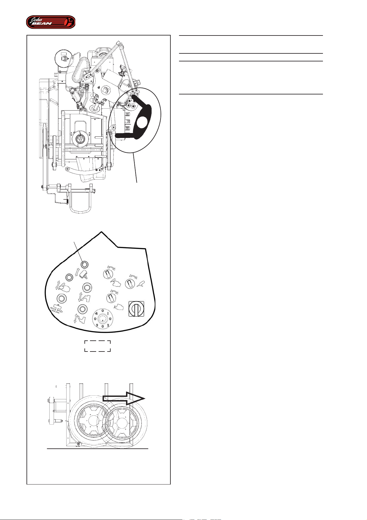
A
Operations
WARNING: ONLY THE OPERATOR MAY ACCESS
THE WORK AREA.
WARNING: THE OPERATOR SHOULD STAND CLOSE
TO THE MACHINE IN THE CORRECT WORK
POSITION ON THE SAME SIDE AS THE CONTROL
PANEL.
• Move lever 1 (Fig. 4.1-2) on the Control Unit
forward to perform the automatic wheel lift procedure.
The machine beeps to warn that the procedure is running
and the operating tools move to the idle position).
The load procedure ends when the wheel is resting
against the flange, the lifters have moved back to the
idle position and the beeper stops beeping.
5.1.1.2 Unloading the wheel
Unclamp the wheel as described in the relative chapter.
Remove the clamping cone
Move the shaft to the right down position.
1
4.1-2
Check that there is not already another wheel on the
front lifter (this would make the unloading procedure
impossible)
• Move lever 1 (Fig. 4.1-2) on the Control Unit back
to perform the automatic wheel unload procedure.
The tools move to the idle position and the Wheel
Support moves to the correct position.
The procedure ends when the lifter stops, having
practically reached the ground, and the beeper stops
beeping.
Figure 5.1.1-3
WARNING: REMOVE THE WHEEL FROM THE
LIFTER MANUALLY ON THE RIGHTHAND SIDE.
72
5.1-3
Operator’s Manual
QUADRIGA 1000/BB
Page 73

Opérativité
Betrieb
A TTENTION : SEUL L'OPERATEUR PEUT OCCUPER
LA ZONE DE TRAVAIL.
A TTENTION : L'OPERATEUR DOIT SE TROUVER A
PROXIMITE DE LA MACHINE, DANS UNE POSITION
DE TRAVAIL CORRECTE ; COTE UNITE DE
COMMANDE (A).
• Actionner en avant la manette 1 (Fig. 4.1-2) de
l'Unité de Commande, pour effectuer la procédure
automatique d'élévation roue.
L'avertisseur sonore s'active pour avertir que la procédure
est en cours et les outils opérationnels de la machine
se déplacent en position hors travail).
La procédure de chargement se termine quand la roue
se trouve en appui sur la bride, les élévateurs sont
retournés en position de repos et l'avertisseur sonore
se désactive.
5.1.1.2 Déchargement Roue
ACHTUNG: NUR DER BEDIENER DARF SICH IM
ARBEITSBEREICH AUFHALTEN.
ACHTUNG: DER BEDIENER MUSS SICH IN DER
NÄHE DER MASCHINE UND IN DER RICHTIGEN
ARBEITSSTELLUNG AUF DER SEITE DER
STEUEREINHEIT BEFINDEN (A).
• Das Bedienelement (1, Abb. 4.1-2) an der
Steuereinheit nach vorne drücken, damit das Rad
automatisch angehoben wird.
Das akustische Signal wird aktiviert, um anzuzeigen,
dass der Vorgang läuft, und die Werkzeuge der Maschine
fahren in die Stellung außerhalb des Arbeitsbereichs.
Der Vorgang des Ladens endet, wenn das Rad auf dem
Flansch aufliegt, die Heber in die Ruhestellung
zurückgekehrt sind und das akustische Signal
deaktiviert wurde.
5.1.1.2 Das Rad abladen
Débloquer la roue, voir rubrique correspondante.
Retirer le cône de blocage
Mettre l'arbre tout en bas.
Vérifier si l'élévateur frontal ne contient pas déjà une
roue (la procédure de déchargement ne serait pas
possible)
• Actionner en arrière la manette 1 (Fig. 4.1-2) de
l'Unité de Commande, pour effectuer le déchargement
de la roue.
Les outils sont conduits en position de repos, le Porteroue se déplace dans la position correcte.
La procédure se termine avec l'arrêt de l'élévateur à
proximité du sol et l'avertisseur sonore désactivé.
Figure 5.1.1-3
ATTENTION: RETIRER LA ROUE DE L'ELEVATEUR
MANUELLEMENT VERS LA DROITE.
Das Rad abspannen, wie in dem entsprechenden Kapitel
beschrieben.
Den Spannkegel entfernen.
Das Spannfutter in die Position ganz unten bringen.
Prüfen, ob der Frontheber bereits ein Rad enthält (sonst
könnte man das Rad nicht abladen)
• Das Bedienelement (1, Abb. 4.1-2) an der
Steuereinheit nach hinten drücken, um den
automatischen Vorgang des Radabladens auszuführen.
Die Werkzeuge werden in die Ruhestellung gefahren
und die Radhalterung bewegt sich in die korrekte
Position.
Der Vorgang ist beendet, wenn der Heber fast am Boden
angehalten hat und das akustische Signal deaktiviert
wurde.
Abbildung 5.1.1-3
ACHTUNG: DAS RAD VON HAND NACH RECHTS
AUS DER HEBEBÜHNE ENTFERNEN.
Manuel d’Utilisation QUADRIGA 1000/BBQUADRIGA 1000/BB
Betriebsanleitung
73
Page 74
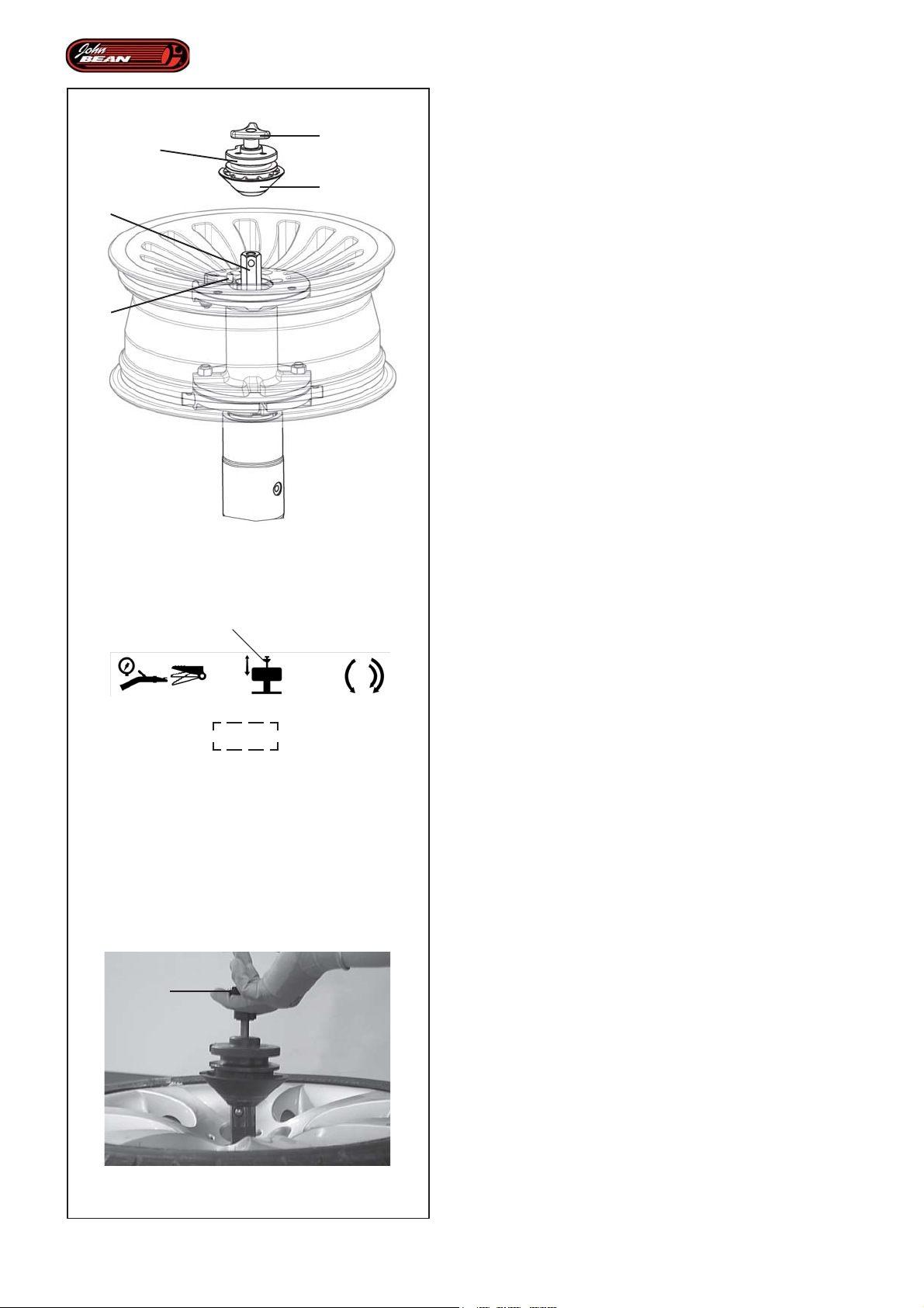
Operations
5.1.2 Clamping - Unclamping the wheel
3
2
1
5.1-4
2
4.1-3
5
Note: In the case of wheels without a central hole
4
Below is a list of the different types of non-standard
wheels that clamping kits are available for:
- REVERSE DROP CENTER WHEELS
- LARGE WHEELS (Van wheels)
- WHEELS WITHOUT A CENTRAL HOLE
5.1.2.1 Clamping the wheel
Figure 5.1.3-1
To complete the wheel or rim loading operation on the
Wheel Holder Flange, proceed as follows:
• Rotate the rim on the flange until the grip pin 1 is
brought inside one of the securing holes on the wheel.
• Check that the machine is in Manual Mode.
• Use the control (2, Fig. 4.1-3) to lift the hexagonal
rod 2.
• Prepare the clamping unit 3, with the cone 4, required
for the hole diameter and the type of rim you are
clamping.
• Insert the complete clamping tool onto the hexagonal
rod 2.
or with a hole that is unsuitable for
clamping, special adapters are available
as accessories; these allow the wheel to
be locked in place using the lug nut holes.
See the 'Accessories available on Request'
section.
Note: Before proceeding check that the tool is
gripping as it should be.
• Clamp the rim using the clamp command (2, Fig.
4.1-3).
The wheel is now locked in place and tire mount/demount
tasks can be carried out.
5.1.2.2 Unclamping the wheel
5
5.1-5
To unclamp the wheel:
• Check that the machine is in Manual Mode.
• Activate the pedal command (2, Fig. 4.1-3).
Note: Every time you press the Clamp/Unclamp
command pedal the hexagonal rod will
move in the opposite direction to the
previous one.
• Pull the knob (5, Fig. 5.1.3-1) upwards and remove
the Clamping Unit completely.
74
Operator’s Manual
QUADRIGA 1000/BB
Page 75

Opérativité
Betrieb
5.1.2 Bloccage - Déblocage Roue
Note: Dans le cas de jantes à centre fermé ou
avec un centre ne permettant pas le
blocage, il existe des adaptateurs spéciaux
comme des accessoires sur demande qui
permettent de bloquer les jantes à travers
les orifices pour boulons. Voir rubrique
Accessoires sur demande.
Pour le blocage de jantes de type non standard, il existe
les kits correspondants suivants:
- JANTES A CREUX RENVERSE
- JANTES GRANDES DIMENSIONS (Van Weel)
- JANTES A CENTRE FERME
5.1.2.1 Blocage Roue
Figure 5.1.3-1
Une fois le chargement de la roue ou de la jante terminé,
procéder comme suit:
• Tourner la jante sur la bride pour amener l'Axe
d'accrochage 1 à l'intérieur d'un des orifices pour la
fixation de la roue.
• Vérifier si le Mode Manuel est activé.
• Avec la commande (2, Fig. 4.1-3), soulever la tige
hexagonale 2.
• Préparer le Groupe de Blocage 3, avec le cône
correspondant 4, en fonction du diamètre de l'orifice
et du type de jante à bloquer.
• Introduire l'outil de blocage complet, sur la tige
hexagonale 2.
Note: Vérifier si l'accrochage a bien eu lieu avant
de continuer.
• Bloquer la jante avec la commande (2, Fig. 4.1-3).
La roue est maintenant bloquée et prête pour les
opérations de Démontage / Montage du pneu.
5.1.2 Das Rad aufspannen - abspannen
Anmerkung: Für Räder ohne Mittenloch oder solche,
deren Mittenloch nicht zum Aufspannen
geeignet ist, gibt es als Zubehör auf
Bestellung spezielle Adapter, mit denen
die Felgen durch die
Schraubenbohrungen aufgespannt
werden können. Siehe dazu das Kapitel
über das Zubehör auf Bestellung.
In der Folge finden Sie eine Liste von Radtypen, die
nicht zum Standard gehören - um sie aufzuspannen,
sind entsprechende Sets verfügbar:
- RÄDER MIT UMGEKEHRTEM BETT
- SEHR GROSSE RÄDER (Van Wheel)
- RÄDER OHNE MITTENLOCH
5.1.2.1 Das Rad aufspannen
Abbildung 5.1.3-1
Nachdem das Rad oder nur die Felge auf den
Radhalterflansch geladen wurden, geht man
folgendermaßen vor:
• Die Felge am Flansch drehen, bis der Einhakstift 1
in eines der Löcher zur Radbefestigung eintritt.
• Sicherstellen, dass der Manualbetrieb (Manual Mode)
aktiviert ist.
• Mit dem Steuerelement (2, Abb. 4.1-3) den
Sechskantstab 2 anheben.
• Die Aufspanneinheit 3 mit dem geeigneten Kegel 4
für den Durchmesser des Lochs und für den Typ der
aufzuspannenden Felge vorbereiten.
• Das gesamte Aufspannwerkzeug am Sechskantstab
2 einführen.
Anmerkung: Stellen Sie sicher, dass es richtig
eingehakt ist, bevor Sie fortfahren.
• Die Felge mit dem Steuerelement (2, Abb. 4.1-3)
aufspannen.
Nun ist das Rad aufgespannt und der Reifen kann
montiert bzw. demontiert werden.
5.1.2.2 Déblocage Roue
Pour débloquer la roue:
• Vérifier si la condition Mode manuel est activée.
• Actionner la pédale de commande (2, Fig. 4.1-3).
Note: A chaque pression de la pédale de la
commande Blocage/Déblocage, on obtient
un mouvement de la tige hexagonale dans
la direction opposée à la précédente.
• Tirer la manette (5, Fig. 5.1.3-1) vers le haut et retirer
complètement le Groupe de Blocage.
Manuel d’Utilisation QUADRIGA 1000/BBQUADRIGA 1000/BB
5.1.2.2 Das Rad abspannen
Um das Rad abzuspannen, geht man folgendermaßen vor:
• Sicherstellen, dass der Manualbetrieb (Manual Mode)
aktiviert ist.
• Das Steuerpedal (2, Abb. 4.1-3) betätigen.
Anmerkung: Jedes Mal, wenn man das Steuerpedal
zum Auf-/Abspannen drückt, bewegt
sich der Sechskantstab in die
entgegengesetzte Richtung zu seiner
letzten Bewegung.
• Den Handgriff (5, Abb. 5.1.3-1) nach oben ziehen
und die Aufspanneinheit vollständig abnehmen.
Betriebsanleitung
75
Page 76
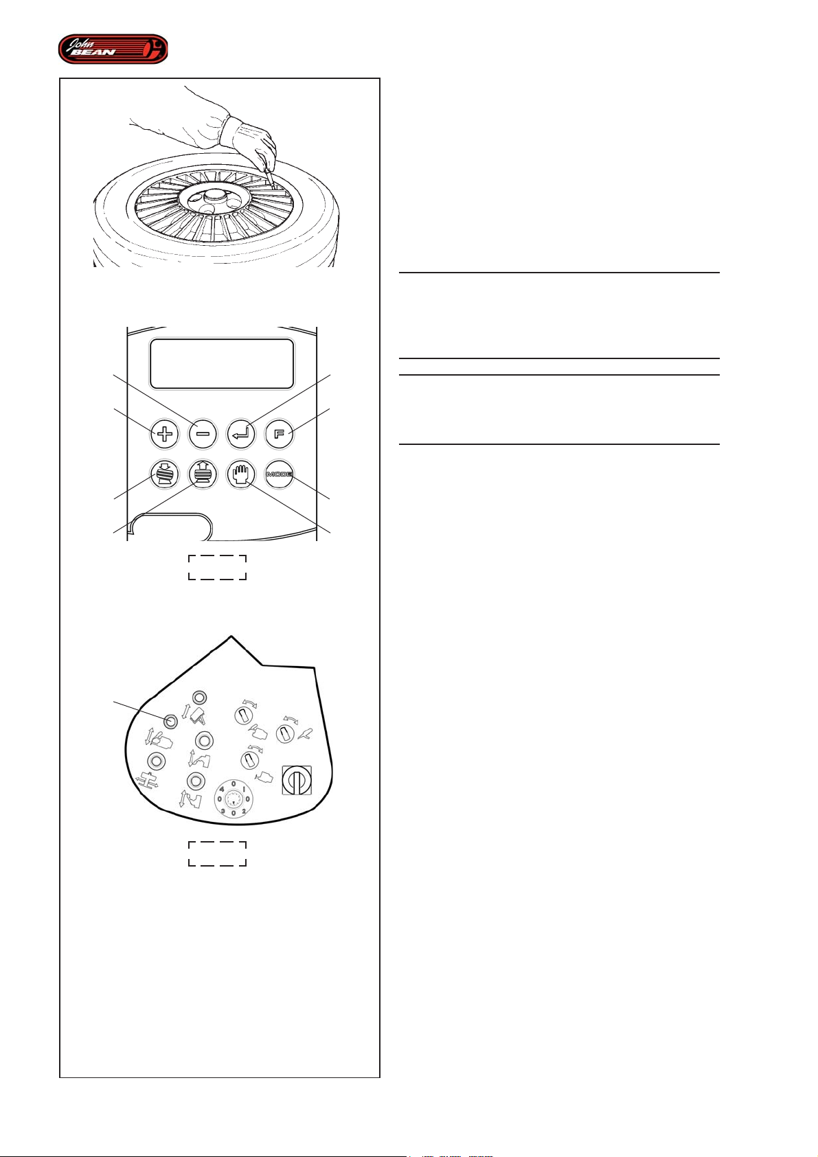
Operations
5.2 Demounting and mounting tires
automatically
Having clamped the wheel on the Wheel Holder Flange,
proceed as follows:
• Remove all wheel-weights from the rim flanges.
• Remove the valve to deflate the tire. (Fig.5.2-1).
• Establish the rim diameter and enter it using keys 1
and 2 on the User Interface (Fig. 4.1-1).
5.2-1
2
1
5
6
4.1-1
3
4
8
7
2
WARNING:
ENTERING INCORRECT DATA MAY CAUSE
DAMAGE TO THE MACHINE AND THE PARTS
BEING WORKED ON AND PUT THE OPERATOR
AT RISK.
WARNING:
THE MACHINE WILL NOT ALLOW THE SET
DIAMETER TO BE CHANGED ONCE THE LASER
HAS SCANNED THE RIM PROFILE.
• Check whether the type of tire in use needs a
different Wheel Mode to the one preset on the
machine. If necessary alter the selection using key
(8, Fig. 4.1-1). See Wheel Mode Selection chapter.
Note: Most wheels can be processed in NORMAL
mode, which is set by default when the
program starts up.
Note: The display always shows which Wheel Mode
is in use at a particular time.
• Select the Automatic Demounting function, using
key (6, Fig. 4.1-1).
The machine is now ready to start the automatic tire
demounting operation.
Note: The display shows information regarding tire
condition, Full Tire Remove and the lever (2,
Fig.4.1-2) that activates the procedure. At the
moment this is the only function enabled to
run the entire work cycle.
76
4.1-2
Operator’s Manual
QUADRIGA 1000/BB
Page 77

Opérativité
Betrieb
5.2 Démontage et Montage
Automatique du pneu
Après avoir bloqué la roue sur la Bride Porte Roue,
procéder comme suit:
• Enlever toutes les masses des bords de la jante.
• Enlever la valve pour dégonfler le pneu. (Fig.5.2-1).
• Identifier le diamètre de la jante et saisir la donnée
avec les touches 1 et 2 de l'Interface Utilisateur (Fig.
4.1-1).
A TTENTION :
UNE ERREUR DANS LA SAISIE DES DONNEES
PEUT PROVOQUER DES DOMMAGES A LA
MACHINE, AUX ELEMENTS EN USINAGE ET A
L'OPERATEUR.
A TTENTION :
LA MACHINE EMPECHE DE MODIFIER LE
DIAMETRE PARAMETRE, APRES LA LECTURE
LASER DU BORD DE LA JANTE.
• Vérifier si le type de pneu utilisé a besoin d'une
sélection Mode Roue différente de celle
présélectionnée par la machine ; le cas échéant,
modifier la sélection avec la touche (8, Fig. 4.1-1).
Voir la rubrique Sélection Mode Roue.
NB: La majorité des roues peuvent être usinées
dans le Mode NORMAL, qui est toujours
présent au démarrage du programme.
NB: L'afficheur montre toujours quel est le Mode Roue
courant utilisé.
• Sélectionner la fonction Démontage Automatique,
touche (6, Fig. 4.1-1).
La machine est prête à commencer le démontage
automatique du pneu.
NB: L'afficheur restitue l'information de l'état, Full Tire
Remove et la Manette (2, Fig.4.1-2) qui active
la procédure est la seule autorisée à lancer le
cycle de travail.
5.2 Automatische Demontage und
Montage des Reifens
Nachdem man das Rad am Radhalterflansch
aufgespannt hat, geht man folgendermaßen vor:
• Alle Ausgleichsgewichte von den Felgenhörnern
entfernen.
• Das Ventil abnehmen, um die Luft aus dem Reifen
abzulassen (Abb.5.2-1).
• Den Durchmesser der Felge feststellen und den Wert
mit den Tasten 1 und 2 der Bedienerschnittstelle
(Abb. 4.1-1) eingeben.
ACHTUNG:
DIE EINGABE FALSCHER WERTE KANN
SCHÄDEN AN DER MASCHINE, AN DEN
BEARBEITETEN ELEMENTEN UND
VERLETZUNGEN DES BEDIENERS
VERURSACHEN.
ACHTUNG:
DIE MASCHINE SPERRT JEDE ÄNDERUNG DES
EINGESTELLTEN DURCHMESSERS, NACHDEM
DER LASER DAS FELGENHORN ERFASST HAT.
• Überprüfen, ob der bearbeitete Reifentyp die Auswahl
eines anderen Radmodus erfordert als den von der
Maschine gewählten. Gegebenenfalls mit der Taste
(8, Abb. 4.1-1) die Vorauswahl ändern. Siehe dazu
das Kapitel "Auswahl des Radmodus".
Anmerkung: Der Großteil der Räder kann im Modus
NORMAL bearbeitet werden, der beim
Start des Programms immer gezeigt
wird.
Anmerkung: Am Display wird immer gezeigt, welcher
Radmodus gerade aktiviert ist.
• Mit der Taste (6, Fig. 4.1-1) die Funktion der
automatischen Demontage auswählen.
Die Maschine ist nun bereit, um mit der automatischen
Demontage des Reifens zu beginnen.
Anmerkung: Am Display wird die Information über den
jeweiligen Zustand gegeben: Full Tire
Remove. Zu diesem Zeitpunkt ist nur
das Bedienelement (2, Abb.4.1-2) zur
Ausführung des Vorgangs und zur
Abwicklung des Betriebszyklus
freigegeben.
Manuel d’Utilisation QUADRIGA 1000/BBQUADRIGA 1000/BB
Betriebsanleitung
77
Page 78
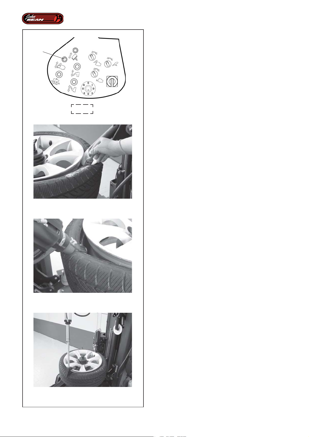
Operations
5.2.1 Demounting
Bead Breaking Procedure
2
• Move the lever (2, Fig.4.1-2) forwards to perform the
following operations:
- The wheel is moved up to the bead breaking disks
and the bead breaking phase begins.
While the discs are operating on the tire you can release
the lever and continue the rotation procedure using the
pedal. This allows the beaks to be lubricated as required
(Fig.5.2-2).
4.1-2
5.2-2
- The machine begins reading the rim profile using a
laser pointer that acquires the exact dimensions.
Note: Having completed the upper bead breaking
operations the machine scans the rim profile
using a laser pointer to acquire the exact
positions.
- After bead breaking, the disks move away from the
tire so the upper automatic tool can position itself
next to the upper bead in order to commence work.
Upper bead removal procedure
• Activate the lever and keep it activated to continue
with the procedure, i.e. until the tool has gripped
onto the upper bead (Fig.5.2-3).
The machine stops automatically (and beeps).
Note: If a SOFT Wheel Mode has been selected,
the cycle moves directly onto the next step
without stopping temporarily.
The operator should:
• Release the lever.
5.2-3
5.2-4
• Check that the Grip operation has been completed
successfully.
• Check that the bead re-enters the rim drop center in
a position diametrically opposite to the tool.
Note: If necessary, use the bead pusher to insert
the bead into the rim drop center (Fig.5.2-4).
78
Operator’s Manual
QUADRIGA 1000/BB
Page 79

Opérativité
Betrieb
5.2.1 Démontage
Procédure de Déjantage
• Actionner la Manette en avant (2, Fig.4.1-2) pour
obtenir les opérations suivantes:
- La roue va à hauteur des disques détalonneurs et la
phase de déjantage commence.
Au cours de l'action des disques sur le pneu, il est possible
de relâcher la Manette de commande et de poursuivre la
rotation avec le Pédalier, ce qui permet de lubrifier les
talons si c'est nécessaire (Fig.5.2-2).
- La machine commence la lecture du profil de la jante
avec le pointeur laser, pour l'acquisition des
dimensions effectives.
NB: A la fin du Déjantage supérieur, la machine
commence le balayage du profil de la jante,
pour l'acquisition des positions effectives avec
le pointeur laser.
- Après le Déjantage, les disques s'éloignent du pneu,
puis l'outil automatique supérieur se place à
proximité du talon supérieur pour l'usinage.
Procédure de décollement du talon supérieur
5.2.1 Demontage
Vorgehen zum Abdrücken
• Das Bedienelement (2, Abb.4.1-2) vorwärts drücken,
um folgende Operationen zu aktivieren:
- Das Rad fährt an die Wulstablösscheiben und die
Abdrückphase beginnt.
Während der Aktitivät der Scheiben am Reifen kann das
Bedienelement losgelassen werden und man kann die
Drehung mit der Pedalsteuerung fortführen; dabei kann
man die Wülste je nach Notwendigkeit schmieren
(Abb.5.2-2).
- Die Maschine beginnt mit der Messung des
Felgenprofils durch den Laserzeiger, um die
tatsächlichen Abmessungen zu erfassen.
Anmerkung: Am Ende des Abdrückens des oberen
Wulstes beginnt die Maschine mit
dem Scannen des Felgenprofils zur
Erfassung der tatsächlichen
Positionen mit dem Laserzeiger.
- Nach dem Abdrücken entfernen sich die Scheiben
vom Reifen und das obere automatische Werkzeug
positioniert sich für die Bearbeitung in der Nähe des
oberen Wulstes.
• Maintenir la Manette actionnée pour continuer avec
la procédure, jusqu'à ce que le talon supérieur soit
effectivement accroché par l'outil (Fig.5.2-3).
Après quoi, les opérations s'arrêtent automatiquement
(on entend un "bip").
NB: Si le Mode Roue SOFT est sélectionné, la
Phase passe directement au pas suivant, sans
aucun arrêt momentané.
L'opérateur doit:
• Relâcher la Manette.
• Effectuer un contrôle pour vérifier si l'opération
d'accrochage a réussi.
• Vérifier si le talon rentre dans le creux de la jante,
dans la position diamétralement opposée à l'outil.
NB: Le cas échéant, utiliser le presse-talon pour
amener le talon à l'intérieur du creux de la
jante (Fig.5.2-4).
Vorgehen zum Entfernen des oberen Wulstes
• Das Bedienelement weiterhin betätigen, um mit dem
Vorgang fortzufahren, bis der obere Wulst am
Werkzeug eingehakt ist (Abb.5.2-3).
Es folgt ein automatischer Halt (ein Piepton ertönt).
Anmerkung: Falls der Radmodus SOFT ausgewählt
ist, läuft die Phase direkt und ohne
zeitweiligen Halt mit dem nächsten
Schritt weiter.
Der Bediener muss Folgendes tun:
• Das Bedienelement loslassen.
• Prüfen, ob das Einhaken erfolgreich war.
• Prüfen, ob der Wulst im Felgenbett an der Stelle
gegenüber dem Werkzeug liegt.
Anmerkung: Gegebenenfalls verwendet man den
Wulstniederhalter, um den Wulst in
das Felgenbett zu drücken (Abb.5.2-
4).
Manuel d’Utilisation QUADRIGA 1000/BBQUADRIGA 1000/BB
Betriebsanleitung
79
Page 80
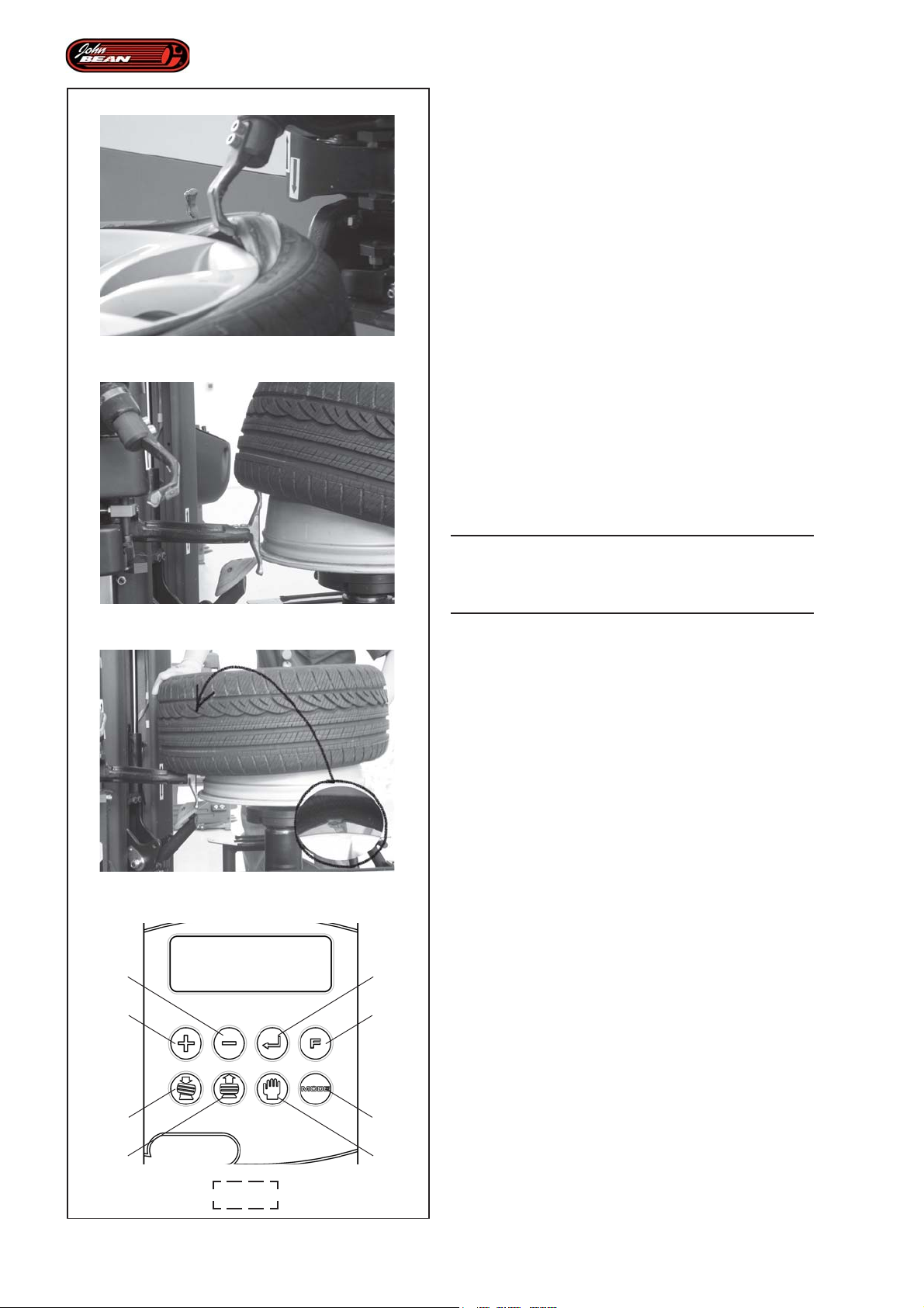
5.2-5
Operations
• Activate rotation using the pedal commands, to
position a pressure sensor (if included) correctly next
to the tool.
Note: In this case the pedal rotation command is
enabled to consent positioning.
• Activate the lever and keep it activated to extract the
upper bead (Fig.5.2-5).
Note: If there is excessive force in the bead
extraction movement the automated
movement interruption may be triggered to
protect the electrical motor. The operation is
therefore suspended.
In such a case, to restart the operator must:
- Release the consent lever.
- Activate the lever once again.
At the fifth interruption the H17 is shown on
the display.
Press key (7 Fig.4.1-1) once to remove the
message and if necessary proceed with
further attempts.
WARNING:
STOP ROTATION AT THE RIGHT MOMENT TO
AVOID THE BEADPUSHER AIDS COLLIDING WITH
5.2-6
5.2-7
2
1
3
4
THE TOOL.
• If applied, remove the bead pusher from the wheel.
Lower bead removal procedure
• Activate the lever and keep it activated to move the
upper tool to the idle position and the lower tool under
the wheel so it can be inserted between the tire and
the rim (Fig.5.2-6).
The machine stops automatically (and beeps).
The operator should:
• Lift the tire manually on the opposite side to the tool,
in order to hook the bead onto the tool (Fig.5.2-7).
• Activate the lever again until the tire has been
completely extracted.
• Continue with the command to enable the tools to
reach the work position for the next Tire Mounting
Program.
80
The machine stops automatically (and beeps).The
"MANUAL MODE" message is shown on the display.
The Automatic Demounting Program is now complete.
5
6
4.1-1
8
7
WARNING:
WHEN THE UNCLAMP RIM PEDAL IS PRESSED ALL
THE ACQUIRED DATA IS DELETED.
Operator’s Manual
QUADRIGA 1000/BB
Page 81

Opérativité
Betrieb
• Actionner la rotation avec le Pédalier, pour placer
correctement un éventuel capteur de pression, si
présent, à proximité de l'outil.
NB: Dans ce cas, la commande de rotation à
pédale est autorisée pour permettre
l'orientation.
• Actionner et maintenir la Manette pour décoller le
talon supérieur (Fig.5.2-5).
Nota: Si l’effort à fournir pour extraire le talon est
trop élevé, un automatisme d’interruption du
mouvement servant à préserver le moteur
électrique pourrait intervenir. L’action est donc
suspendue.
Dans ce cas, pour redémarrer, l’opérateur doit :
- Relâcher la manette.
- Puis l’actionner à nouveau.
A la cinquième interruption, l’afficheur montre
H17.
Presser une fois la touche (7 Fig.4.1-1), pour
effacer le message et, le cas échéant,
procéder à d’autres tentatives.
A TTENTION:
ARRETER LA ROTATION AU MOMENT
OPPORTUN, POUR EVITER LA COLLISION
ENTRE L'OUTIL ET LE PRESSE-TALON.
• Le cas échéant, retirer le presse-talon de la roue.
Procédure de Décollement du talon inférieur
• Mit der Pedalsteuerung die Drehung aktivieren, um
den Drucksensor (falls vorhanden) ordnungsgemäß
in die Nähe des Werkzeugs zu bringen.
Anmerkung: In diesem Fall ist die Ansteuerung der
Drehung mit dem Pedal freigegeben,
um die Ausrichtung zu ermöglichen.
• Das Bedienelement betätigen und halten, um den
oberen Wulst abzuziehen (Abb.5.2-5).
Anmerkung: Damit der betreffende Elektromotor im Falle
einer hohen Beanspruchung bei der
Bewegung zum Abziehen des Wulstes nicht
überlastet wird, kann es geschehen, dass
die Bewegung automatisch angehalten wird.
In diesem Fall ist die Operation unterbrochen.
Um neu zu starten, muss der Bediener
Folgendes tun:
- Das Bedienelement zur Freigabe loslassen.
- Das Bedienelement noch einmal betätigen.
Bei der fünften Unterbrechung zeigt das
Anzeigegerät H17.
Einmal die Taste (7, Abb.4.1-1) drücken, um
die Meldung zu entfernen, und
gegebenenfalls weiter versuchen.
ACHTUNG:
DIE DREHUNG MUSS ZUM RICHTIGEN
ZEITPUNKT ANGEHALTEN WERDEN, UM ZU
VERHINDERN, DASS DIE WULSTNIEDERHALTER
MIT DEM WERKZEUG ZUSAMMENSTOSSEN.
• Actionner et maintenir la Manette jusqu'à ce que l'outil
supérieur aille en position hors travail et l'outil inférieur
aille en dessous de la roue, pour s'introduire entre le
pneu et la jante (Fig.5.2-6).
Après quoi, les opérations s'arrêtent automatiquement
(On entend un "bip").
L'opérateur doit:
• Soulever manuellement le pneu du côté opposé à
l'outil, pour accrocher le talon à l'outil lui-même
(Fig.5.2-7).
• Actionner à nouveau la Manette pour décoller
complètement le pneu.
• Continuer avec la commande pour permettre aux
outils d'atteindre la position utile au Programme de
Démontage du pneu suivant.
Après quoi, les opérations s'arrêtent automatiquement
(On entend un "bip"). L'afficheur montre "MODE
MANUEL".
Le Programme Automatique Démonte-pneu est terminé.
A TTENTION :
SI ON APPUIE SUR LA PEDALE DE DEBLOCAGE
JANTE, LES DONNEES ACQUISES SERONT
PERDUES.
• Falls der Wulstniederhalter angebracht wurde, wird
er nun vom Rad entfernt.
V orgehen zum Entfernen des unteren Wulstes
• Das Bedienelement betätigen und halten, bis das
obere Werkzeug in die Stellung außerhalb des
Arbeitsbereichs gefahren ist und sich das untere
Werkzeug unter das Rad bringt, um sich zwischen
den Reifen und die Felge einzufügen (Abb.5.2-6).
Es folgt ein automatischer Halt (ein Piepton ertönt).
Der Bediener muss Folgendes tun:
• Den Reifen mit der Hand auf der Seite gegenüber
dem Werkzeug anheben, um den Wulst am
Werkzeug einzuhaken (Abb.5.2-7).
• Das Bedienelement wieder betätigen, bis der Reifen
völlig abgezogen ist.
• Das Bedienelement weiter betätigen, damit die
Werkzeuge in die richtige Position zu dem nun folgenden
Programm zur Montage des Reifens fahren können.
Es folgt ein automatischer Halt (ein Piepton ertönt). Am
Display wird "MANUAL MODE" gezeigt.
Das automatische Demontageprogramm ist abgeschlossen.
ACHTUNG:
WENN MAN DAS PEDAL ZUM ABSPANNEN DER FELGE
DRÜCKT, GEHEN DIE ERFASSTEN DATEN VERLOREN.
Manuel d’Utilisation QUADRIGA 1000/BBQUADRIGA 1000/BB
Betriebsanleitung
81
Page 82
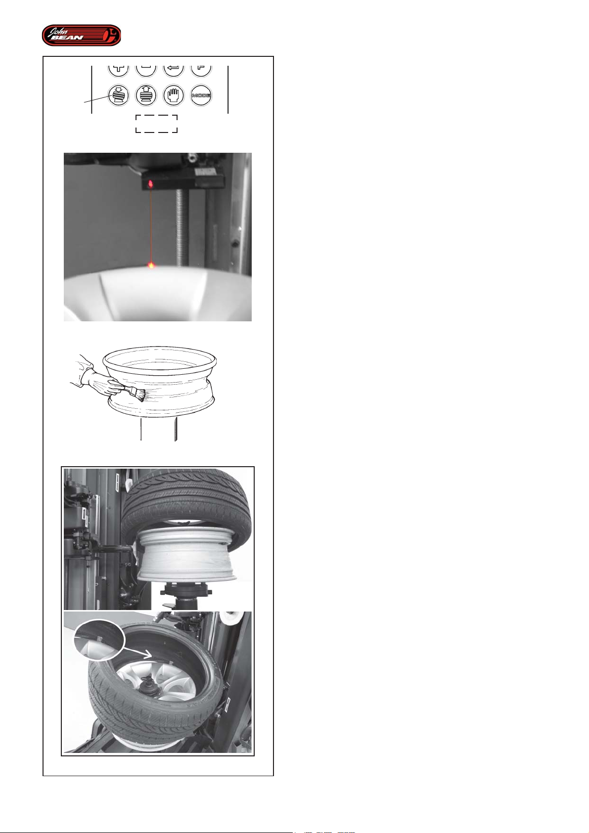
Operations
5.2.2 Mounting
5
4.1-1
5.2-8
Having completed demounting, only the rim will be left
clamped onto the Wheel Holder Flange.
Proceed as follows:
WARNING:
CHECK THAT THE DIAMETER OF THE TIRE BEING
MOUNTED IS CORRECT.
Lower bead mounting procedure
• Select the Automatic Mounting function key (5, Fig.
4.1-1).
Note: If a tire mounting operation is performed after
a rim clamping operation (new rim or rim
removed after demounting) the first thing the
machine does is to scan the rim flange (Laser
Scan Fig.5.2-8).
• Activate the Lever to position the lower mounting tool
in the start up position.
The machine stops automatically (and beeps) to allow
the rim to be lubricated and the tire to be positioned.
• Activate the rotation command pedal and lubricate
the rim (Fig.5.2-9).
5.2-9
Note: In this situation rotation can be activated using
the pedal command so the operator can
lubricate the rim.
• Place the new tire on the rim, and hook the bead
onto the tool as shown (Fig.5.2-10).
• Using ONLY the rotation command PEDAL finish
inserting the lower bead into the upper part of the
rim.
WARNING:
DO NOT ACTIVATE THE LEVER BEFORE YOU HAVE
COMPLETED THE BEAD INSERTION OPERATION
USING THE PEDAL.
82
5.2-10
Operator’s Manual
QUADRIGA 1000/BB
Page 83

Opérativité
Betrieb
5.2.2 Montage
L'opération de démontage terminée, la jante seule se
trouve bloquée sur la Bride Porte Roue.
Procéder comme suit:
A TTENTION :
VERIFIER SI LE DIAMETRE DU PNEU MONTE EST
CORRECT.
Procédure de Montage du talon Inférieur
• Sélectionner la fonction Montage Automatique,
touche (5, Fig. 4.1-1).
NB: Si on effectue le montage d'un pneu après
une opération de blocage de la jante (nouvelle
jante ou retirée après le démontage), la
première opération de la machine est la
détection du bord de la jante (Balayage Laser
Fig.5.2-8).
• Actionner la Manette ; l'outil de montage inférieur se
positionne pour le démarrage de la procédure.
Après quoi, on a un arrêt automatique (on entend un
"bip") pour permettre la lubrification de la jante et le
positionement du pneu.
• Actionner la pédale de commande rotation et lubrifier
la jante (Fig.5.2-9).
NB: Dans ce cas, la rotation est permise avec la
commande à pédale pour effectuer la
lubrification.
• Placer le nouveau pneu sur la jante, en accrochant
le talon à l'outil, comme il est représenté (Fig.5.2-
10).
• EXCLUSIVEMENT AVEC LA PEDALE de
commande rotation, compléter l'introduction du talon
inférieur dans la partie supérieure de la jante.
A TTENTION :
NE PAS ACTIONNER LA MANETTE AVANT D'AVOIR
TERMINE L'ENJANTAGE AVEC LA PEDALE.
5.2.2 Montage
Nach der Demontage ist nur noch die Felge am
Radhalterflansch aufgespannt.
Man geht folgendermaßen weiter vor:
ACHTUNG:
PRÜFEN, OB DER DURCHMESSER DES ZU
MONTIERENDEN REIFENS RICHTIG IST.
Vorgehen zur Montage des unteren Wulstes
• Die Funktion der automatischen Montage wählen
(mit der Taste (5, Abb. 4.1-1).
Anmerkung: Wenn man einen Reifen nach dem
Aufspannen einer Felge montiert
(Felge neu oder nach der Demontage
entfernt), ist die erste Operation der
Maschine das Erfassen des
Felgenhorns (Laserscannen Abb.5.2-
8).
• Das Bedienelement betätigen; das untere
Montagewerkzeug positioniert sich für den Beginn
des Vorgangs.
Es folgt ein automatischer Halt (ein Piepton ertönt),
damit die Felge geschmiert und der Reifen richtig
positioniert werden kann.
• Das Steuerpedal für die Drehung betätigen und die
Felge schmieren (Abb.5.2-9).
Anmerkung: In diesem Fall ist die Drehung über
die Pedalsteuerung freigegeben, um
die Felge zu schmieren.
• Den neuen Reifen an der Felge anbringen und den
Wulst wie dargestellt am Werkzeug einhaken
(Abb.5.2-10).
• NUR MIT DEM PEDAL zur Steuerung der Drehung
den unteren Wulst vollständig in den oberen Teil der
Felge einfügen.
ACHTUNG:
DAS BEDIENELEMENT NICHT WIEDER BETÄTIGEN,
BIS DAS EINFÜGEN DES WULSTES MIT DEM
PEDAL ABGESCHLOSSEN IST.
Manuel d’Utilisation QUADRIGA 1000/BBQUADRIGA 1000/BB
Betriebsanleitung
83
Page 84
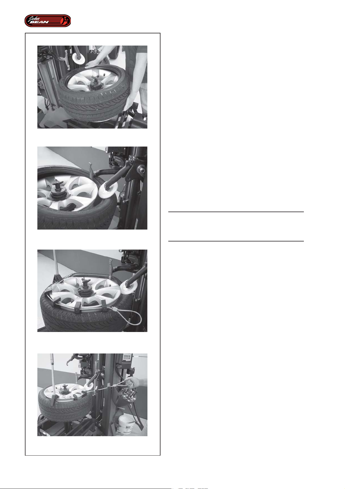
5.2-11
Operations
• Then activate the Lever until the tools move to the
upper side of the wheel.
The machine stops automatically (and beeps).
• Lift the tire manually to create a space next to the
tool that it can enter (Fig.5.2-11).
• Activate the Lever again to insert the tool and the
disk between the tire and the rim (Fig.5.2-12).
The machine stops automatically (and beeps).
The operator must be able to:
• Operate rotation using the Pedal Command in order
to move the Pressure Sensor, if included, to a suitable
position in relation to the tool.
• Use one of the bead pushing aids supplied:
- Manual Clamp
- MH (Pneumatically-controlled Bead Pusher)
- Bead Pusher Inserts
Or a combination of the above (Fig.5.2-13).
5.2-12
5.2-13
• Complete the bead insertion procedure by
continuing rotation, making sure that the tool does
not collide with the bead pushing aids.
WARNING:
STOP ROTATION AT THE RIGHT MOMENT TO
AVOID THE BEADPUSHER AIDS COLLIDING WITH
THE TOOL.
Having completed mounting, to facilitate the removal of
the mounting aids:
• Rotate the wheel in the opposite direction, until it
reaches the bead breaking disk (Fig.5.2-14), as in
this position it is easier to remove.
• Activate the Lever again until the tools and disks
have left the work area and returned to the idle
position.
Note: During the tools “Homing” phase, the pedal
rotation command is enabled to speed up the
operating flow.
• Turn the wheel contemporaneously as the tools
movement, until the valve is close by for the subsequent
bead insertion operation.
84
5.2-14
When the tools reach the rest position, the machine
stops automatically (and beeps) and the "MANUAL
MODE" message appears again on the Display.
Operator’s Manual
QUADRIGA 1000/BB
Page 85

Opérativité
Betrieb
• Actionner la Manette jusqu'à ce que les outils aillent
sur le côté supérieur de la roue.
Après quoi, on a un arrêt mécanique (on entend un "bip").
• Soulever manuellement le pneu pour obtenir un
espace d'entrée à hauteur de l'outil (Fig.5.2-1 1).
• Poursuivre avec la Manette pour amener l'outil et le
disque entre le pneu et la jante (Fig.5.2-12).
Après quoi, on a un arrêt automatique (signalé par un
"bip").
L'opérateur est en mesure de:
• Opérer la rotation avec la Commande à Pédale, pour
amener l'éventuel Capteur de Pression dans la bonne
position par rapport à l'outil.
• Utiliser un des outils presse-talon disponible:
- Etau Manuel
- MH (Presse-talon à Commande Pneumatique)
- Inserts Presse-talon
Ou une combinaison de ceux-ci (Fig.5.2-13).
• Compléter le jantage en poursuivant la rotation en
faisant attention à ne pas heurter l'outil avec le
presse-talon.
A TTENTION :
ARRETER LA ROTATION AU MOMENT
OPPORTUN, POUR EVITER UNE COLLISION
ENTRE LE PRESSE-TALON ET L'OUTIL.
Le montage terminé, pour faciliter la dépose:
• Tourner dans le sens contraire pour arriver à
proximité du disque détalonneur (Fig.5.2-14), ce qui
favorisera la dépose.
• Poursuivre avec la Manette jusqu'à ce que les outils
et les disques aient libéré la zone de travail, en se
plaçant "hors travail".
La machine s'arrête, émet un "bip" et sur l'afficheur
apparaît à nouveau l'état "MODE MANUEL".
Nota: Au cours de la phase de “Prise d’origine” des
outils, pour accélérer le cours des opérations,
la pédale qui commande la rotation est
activée.
•Faire tourner la roue simultanément au mouvement
des outils, pour approcher vers soi la soupape pour
l’opération d’enjantage à venir.
• Nun das Bedienelement betätigen, bis die
Werkzeuge auf die Oberseite des Rads fahren.
Es folgt ein automatischer Halt (ein Piepton ertönt).
• Den Reifen mit der Hand anheben, um am Werkzeug
eine Eintrittsöffnung herzustellen (Abb.5.2-11).
• Das Bedienelement weiter betätigen, bis sich das
Werkzeug und die Scheibe zwischen den Reifen
und die Felge einfügen (Abb.5.2-12).
Es folgt ein automatischer Halt (ein Piepton ertönt).
Der Bediener kann Folgendes tun:
• Die Drehung mit der Pedalsteuerung starten, um den
Drucksensor (falls vorhanden) in die richtige Position
in Hinsicht auf das Werkzeug zu bringen.
• Eine der Wulstniederhalterhilfen benutzen, die zur
Verfügung stehen:
- Manuelle Radklammer
- MH (Wulstniederhalter mit pneumatischer Steuerung)
- Wulstniederhaltereinsätze
oder eine Zusammenstellung dieser Elemente (Abb. 5.2-
13).
• Das Einfügen des Wulstes abschließen, indem er
mit der Drehung fortfährt. Dabei ist darauf zu achten,
nicht mit den Wulstniederhaltern gegen das
Werkzeug zu stoßen.
ACHTUNG:
DIE DREHUNG IST RECHTZEITIG ANZUHALTEN,
DAMIT DIE WULSTNIEDERHALTER NICHT MIT
DEM WERKZEUG ZUSAMMENSTOSSEN.
Wenn die Montage abgeschlossen ist, geht man zur
leichteren Entfernung der Hilfselemente folgendermaßen
vor:
• In die entgegengesetzte Richtung bis zur
Wulstablösscheibe drehen (Abb.5.2-14); diese
erleichtert das Entfernen.
• Das Bedienelement weiter betätigen, bis die
Werkzeuge und die Scheiben den Arbeitsbereich
freigeben und in die Position "außerhalb des
Arbeitsbereichs" gefahren sind.
Anmerkung: Während des „Homing”-Vorgangs der
Werkzeuge ist die Pedalsteuerung zur
Drehung aktiviert, um den Betriebsfluss
zu beschleunigen.
Quand les outils atteignent la position de repos, la
machine s’arrête, émet un bip et sur l’afficheur apparaît
à nouveau l’état “MODE MANUEL”.
Manuel d’Utilisation QUADRIGA 1000/BBQUADRIGA 1000/BB
• Das Rad gleichzeitig mit der Bewegung der
Werkzeuge drehen, bis das Ventil gut erreichbar ist
(für die folgende Operation des Wulsteindrückens).
Wenn die Werkzeuge die Ruhestellung erreichen, hält
die Maschine an, ein Piepton ertönt und am Display
wird wieder der Zustand des Manualbetriebs
(MANUAL MODE) angezeigt.
Betriebsanleitung
85
Page 86
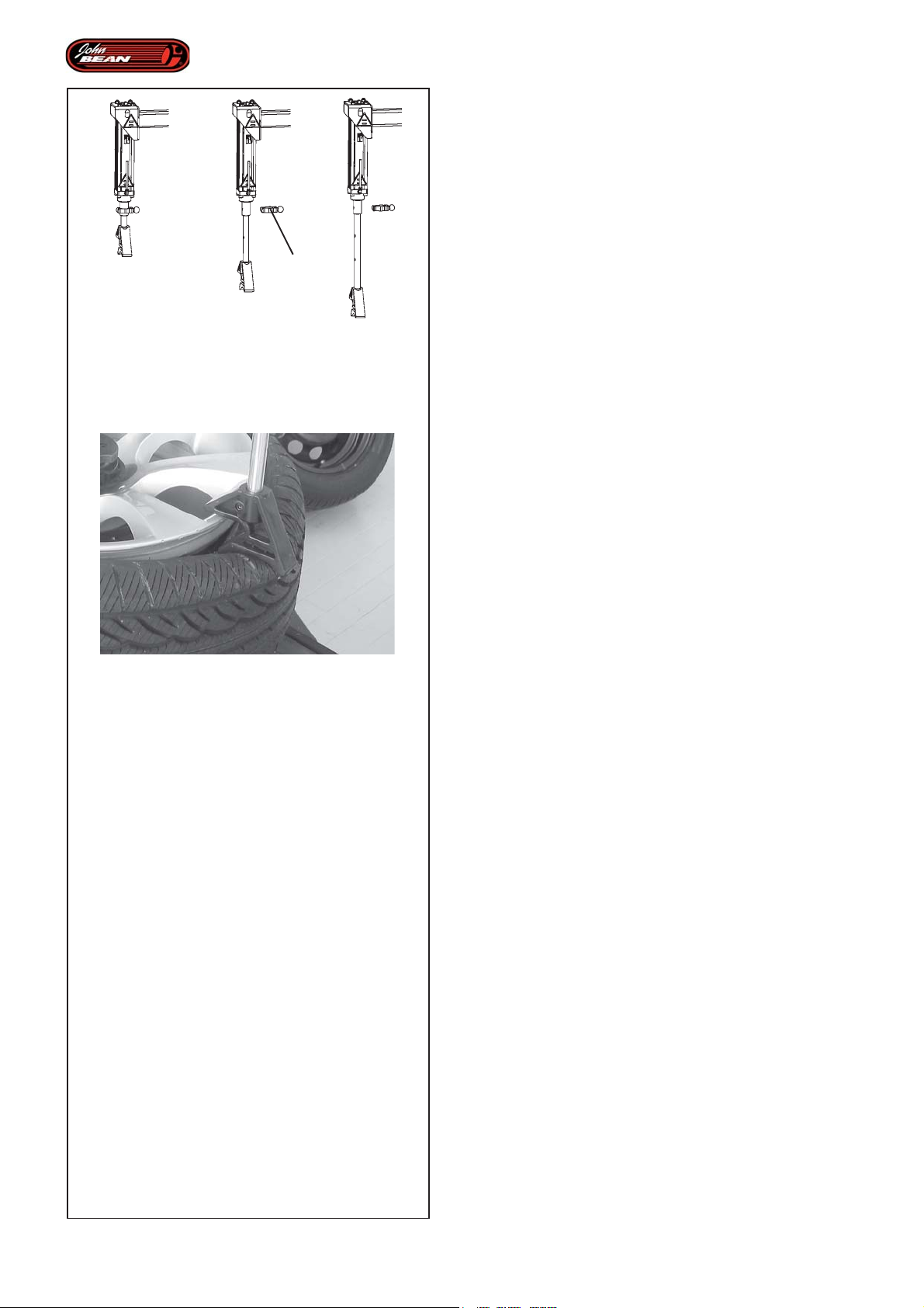
5.2-15
Operations
5.2.3 Using the Bead Pusher MH
To aid demounting of wheels with particularly rigid or
low profile tires it is possible to use either the Bead
Pusher or the Bead Breaker Disc, or use both together.
The bead pusher holder rod position can be set to three
different heights.
1
Figure 5.2-15
• Remove the rod lock stop 1 and adjust the position
as desired.
• Re-insert the stop in the rod lock hole.
Using the Bead Pusher MH
Figure 5.2-16
The Bead Pusher device allows the bead to be held in
the rim drop center and is usually used on the side
diametrically opposite the demount tool.
• Bring the bead pusher device 1 onto the tire in a
position opposite to that of the demount tool.
• Exert a pressure such as to bring the bead to the
height of the rim drop center.
5.2-16
The Bead Pusher tool rests on the rim flange and allows
an even, sufficiently strong pressure to be placed on
the side of the tire.
Note: During the mounting tasks the operator
can make use of the Bead Pusher tool.
86
Operator’s Manual
QUADRIGA 1000/BB
Page 87

Opérativité
Betrieb
5.2.3 Utilisation du Presse-talon MH
Pour faciliter le démontage de roues avec pneus
particulièrement rigides ou surbaissés, il est possible
d'utiliser le Presse-talon et le Disque détalonneur ou
les deux éléments combinés.
La position de la tige de support du presse-talon est
réglable à trois hauteurs différentes.
Figure 5.2-15
• Eliminer l'arrêtoir qui bloque la tringle 1, pour régler
la position souhaitée.
• Re-insert the stop in the rod lock hole.
Actionnement du Presse-talon MH
Figure 5.2-16
Le dispositif Presse-talon permet de retenir le talon à
l'intérieur du creux de la jante et est généralement utilisé
sur le côté diamétralement opposé à l'outil de
démontage.
• Mettre le dispositif presse-talon 1 sur le pneu, dans
la position opposée à l'outil de démontage.
• Exercer une pression pour conduire le talon à
hauteur du creux de la jante.
5.2.3 Anwendung des MH-Wulstniederhalters
Um die Demontage von Rädern mit besonders steifen
oder niedrigen Reifen zu erleichtern, kann man den
Wulstniederhalter und die Wulstablösscheibe oder beide
Elemente zusammen verwenden.
Die Position des Wulstniederhalter-Trägerstabs kann
auf drei unterschiedliche Höhen eingestellt werden.
Abbildung 5.2-15
• Den Feststellstopper des Stabs 1 abnehmen, um
die gewünschte Position einzustellen.
• Den Stopper wieder in die Öffnung setzen, um den
Stab zu blockieren.
Betätigung des MH-Wulstniederhalters
Abbildung 5.2-16
Die Wulstniederhaltervorrichtung ermöglicht es, den
Wulst im Felgenbett zu halten, und wird meistens auf
der Seite gegenüber dem Demontagewerkzeug
eingesetzt.
• Den Wulstniederhalter 1 an der Stelle direkt
gegenüber dem Demontagewerkzeug am Reifen
ansetzen.
• Einen solchen Druck ausüben, dass der Wulst auf
der Höhe des Felgenbetts liegt.
L'Outil Presse-talon prend appui sur le bord de la jante,
de manière à exercer une pression toujours constante
sur le flanc du pneu.
NB: Au cours des opérations de montage,
l'opérateur peut se servir de l'Outil Pressetalon.
Das Wulstniederhalterwerkzeug liegt am Felgenhorn
auf und ermöglicht dadurch, einen immer gleichen und
angemessenen Druck auf die Reifenflanke auszuüben.
Anmerkung: Das Wulstniederhalterwerkzeug
kann auch bei der Montage zu Hilfe
genommen werden.
Manuel d’Utilisation QUADRIGA 1000/BBQUADRIGA 1000/BB
Betriebsanleitung
87
Page 88

Operations
5.4 Beading the tires
Beading means the initial grip of the tire bead on the
rim, in order to allow the inflation operations and
subsequent settling in the seat on the rim.
Safety Precautions:
WARNING: DO NOT USE THE TIRE CHANGER TO
INFLATE TIRES.
COMPRESSED AIR DEVICES ON THE TIRE
CHANGER ARE ONLY DESIGNED TO FACILITA TE
THE TUBELESS TIRE BEADING OPERATION OR T O
SETTLE THE INNER TUBE, ACCORDING TO THE
TYPE OF TIRE.
NEVER EXCEED THE MAXIMUM PRESSURE ALLOWED
BY THE TIRE MANUFACTURER.
THE OPERATOR MUST STAND SAFELY CLEAR FROM
THE WHEEL WHEN BEADING THE TIRE, AND
PRESSURE MUST BE MONITORED FREQUENTLY TO
AVOID EXCESSIVE PRESSURE.
BEFORE BEADING, CHECK THE CONDITION OF TIRE
AND RIM.
CHECK FOR CORRECT SEALING BETWEEN THE VALVE
AND THE FITTING AT THE END OF THE AIR HOSE. AN AIR
LEAK CAN GIVE INCORRECT PRESSURE READINGS
AND CREATE SAFETY HAZARDS
CHECK THAT THE READING ON THE PRESSURE
GAUGE IS “ZERO” WHEN IT IS NOT IN USE.
THE COMPLETE SEATING THE BEAD ON THE RIM IS A
VERY DANGEROUS STAGE OF THE TIRE MOUNTING
PROCEDURE.
TO COMPLETE THE BEADING OPERATION AND
INFLATE THE TIRE CORRECTLY, PLACE IT IN AN
APPROPRIATE TYPE APPROVED CAGE.
88
A TIRE BURST, WHATEVER ITS CAUSE, CAN RESULT IN
SERIOUS INJURY OR DEATH.
AVOID MOUNTING TIRES THAT ARE 1/2" SMALLER IN
DIAMETER THAN THE RIM, DOING SO FAILS TO ENSURE
THAT THE BEADS ARE SEALED PROPERLY IN THEIR
SEATS: THIS COULD BE A SOURCE OF DANGER WHEN
DRIVING.
Operator’s Manual
QUADRIGA 1000/BB
Page 89

Opérativité
Betrieb
5.4 Enjantage du talon des pneus
Par enjantage du talon, on entend l’adhérence intiale
du talon du pneu à la jante, de manière à permettre la
suite des opérations à savoir le gonflage et une parfaite
pénétration du talon dans le logement de la jante.
Consignes de sécurité:
ATTENTION : NE PAS UTILISER LE DEMONTE-
PNEUS COMME DISPOSITIF DE GONFLAGE.
LES DISPOSITIFS DE GONFLAGE A AIR
COMPRIME, PRESENTS SUR LE DEMONTE-PNEUS
ONT COMME BUT DE FACILITER L ’ENJANT AGE DU
TALON DU PNEU TUBELESS OU ENCORE LA
PENETRA TION DE LA CHAMBRE A AIR DANS SON
LOGEMENT , SUIV ANT LE TYPE DE ROUES.
IL EST ABSOLUMENT INTERDIT DE DEPASSER LA
PRESSION MAXIMALE ADMISSIBLE PAR LE FABRICANT
DU PNEUMATIQUE.
L’OPERATEUR DOIT RESTER A UNE DISTANCE DE
SECURITE QUAND IL PROCEDE L’ENJANTAGE DU
TALON DU PNEU. LA PRESSION DOIT ETRE
CONTROLEE FREQUEMMENT POUR EVITER UN
GONFLAGE EXCESSIF.
AVANT D’ENJANTER LE TALON DU PNEU, CONTROLER
L’ETAT DU CAOUTCHOUC ET DE LA JANTE.
5.4 Eindrücken der Reifenwülste
Unter Wulsteindrücken wird verstanden, dass man
die Reifenwülste anfänglich so an der Felge anlegt, dass
das Rad danach gefüllt werden kann und sich die Wülste
dadurch vollständig in ihre Sitzen an der Felge
einfügen.
Vorsichtmaßnahmen:
ACHTUNG: VERWENDEN SIE DAS
REIFENMONTIERGERÄT NICHT ALS
FÜLLVORRICHTUNG.
VORRICHTUNGEN ZUM EINFÜLLEN VON
DRUCKLUFT, DIE AM REIFENMONTIERGERÄT
VORHANDEN SIND, HABEN NUR DEN ZWECK, DAS
WULSTEINDRÜCKEN SCHLAUCHLOSER REIFEN
BZW. DIE ANP ASSUNG DES SCHLAUCHS, JE NACH
RADTYP , ZU ERLEICHTERN.
DER VOM HERSTELLER VORGEGEBENE REIFENDRUCK
DARF IN KEINEM FALL ÜBERSCHRITTEN WERDEN.
BEIM EINDRÜCKEN DES WULSTES MUss DER
BEDIENER dEN SICHERHEITSABSTAND EINHALTEN,
UND DER DRUCK MUss häufig KONTROLLIERT
WERDEN, UM EINEN ÜBERDRUCK ZU VERMEIDEN.
VOR DEM WULSTEINDRÜCKEN EINES REIFENS SIND
DER ZUSTAND DES REIFENS UND DER FELGE ZU
ÜBERPRÜFEN.
S’ASSURER DE L’ETANCHEITE ENTRE LE RACCORD
DE LA VALVE ET L’EXTREMITE DU TUBE D’AIR
COMPRIME. UNE FUITE D’AIR PEUT DETERMINER UNE
LECTURE ERRONEE DE LA PRESSION ET UNE
SITUATION DE DANGER.
VERIFIER SI L’AIGUILLE DU MANOMETRE EST SUR
ZERO, EN CONDITION DE REPOS.
LA PHASE AU COURS DE LAQUELLE LE TALON VIENT
PRENDRE PARFAITEMENT SA PLACE DANS LE
LOGEMENT DE LA JANTE EST UNE PHASE EXTREMEMENT
DANGEREUSE DU MONTAGE D’UN PNEU.
POUR COMPLETER L’ENJANTAGE DU TALON ET
GONFLER LA ROUE CORRECTEMENT, LA PLACER
DANS UNE CABINE HOMOLOGUEE.
QUELLE QU’EN SOIT L’ORIGINE, L’EXPLOSION D’UN
PNEU PEUT PROVOQUER DES BLESSURES GRAVES
VOIRE MORTELLES.
MEME S’IL EST POSSIBLE D’INTRODUIRE DES PNEUS
AYANT UN DIAMETRE DE ½” PLUS PETIT QUE LA JANTE,
LA TENUE DES TALONS DANS LES LOGEMENTS DE LA
JANTE DANS UN TEL CAS N’EST PAS GARANTIE ET
PEUT REPRESENTER UN DANGER POUR LES
OCCUPANTS DU VEHICULE.
SICHERSTELLEN, DASS DER ANSCHLUSSTUTZEN
DES LUFTEINFÜLLSCHLAUCHS FEST AUF DEM VENTIL
SITZT. DURCH EINEN LUFTVERLUST AN DIESER
STELLE KANN DIE DRUCKANZEIGE VERFÄLSCHT
WERDEN, WAS EINE GEFAHR DARSTELLT.
SICHERSTELLEN, DASS DER ZEIGER DES
DRUCKMESSERS IM RUHEZUSTAND AUF ‚NULL’ STEHT.
DIE VÖLLIGE ANPASSUNG DES WULSTES IN DER
FELGE IST EINE SEHR GEFÄHRLICHE PHASE BEI DER
MONTAGE EINES REIFENS.
UM DAS EINDRÜCKEN DES WULSTES
ABZUSCHLIESSEN UND DAS RAD ANGEMESSEN ZU
FÜLLEN, LEGT MAN ES IN EINEN ZUGELASSENEN KÄFIG.
EIN AUS WELCHEN GRÜNDEN AUCH IMMER
PLATZENDER REIFEN KANN SCHWERE ODER SOGAR
TÖDLICHE VERLETZUNGEN VERURSACHEN.
ES IST ZU VERMEIDEN, REIFEN MIT EINEM
DURCHMESSER EINZUSETZEN, DER UM 1/2" KLEINER
IST ALS DIE FELGE. IN DIESEM FALL KANN DER
RICHTIGE HALT DER WÜLSTE IN IHREM SITZ NICHT
GEWÄHRLEISTET WERDEN, WAS IM ENDEFFEKT EINE
GEFAHR BEIM FAHREN DARSTELLT.
Manuel d’Utilisation QUADRIGA 1000/BBQUADRIGA 1000/BB
Betriebsanleitung
89
Page 90
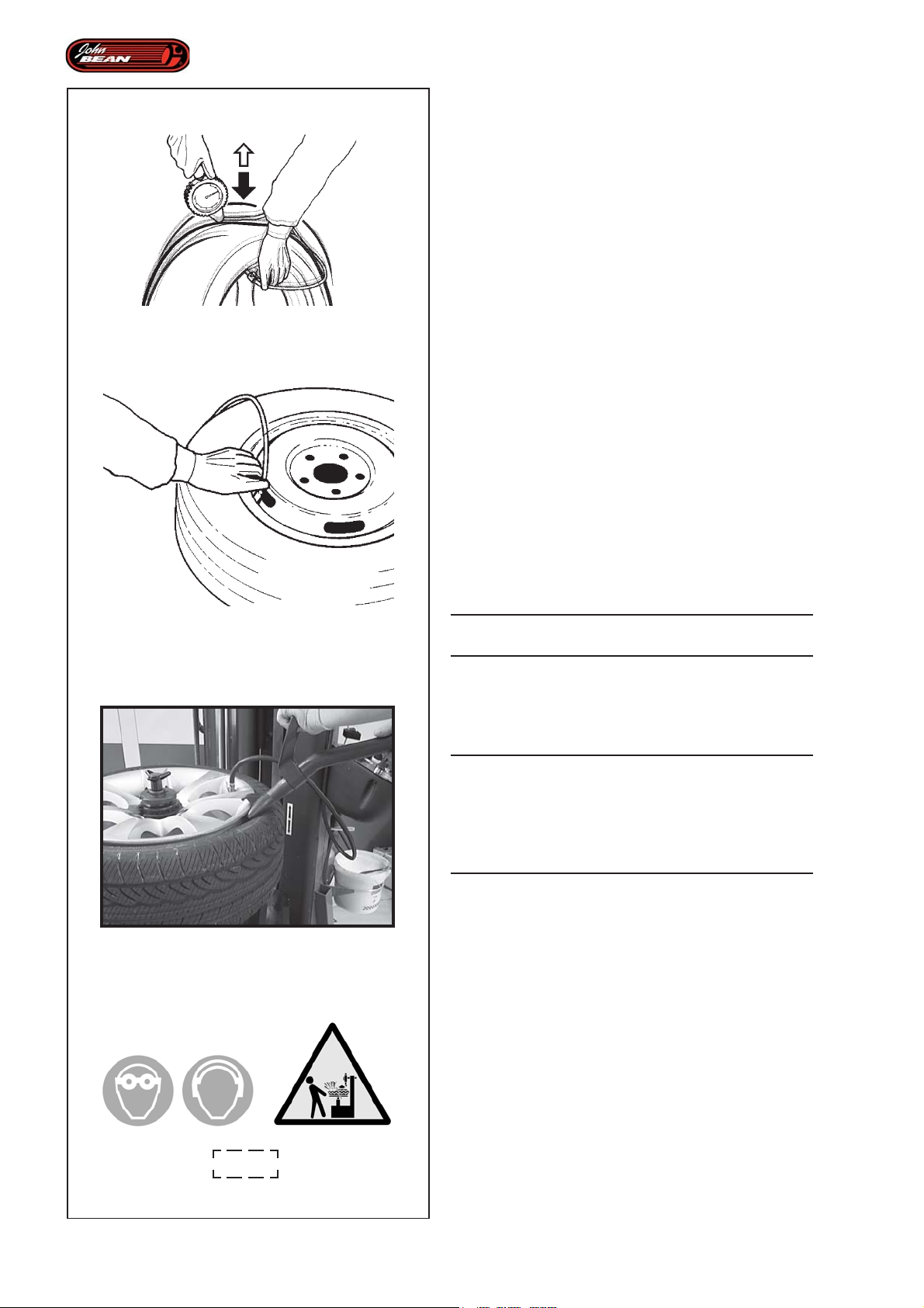
Operations
Beading T ubeless: tires
Perform the beading with the wheel blocked on the tire
changer.
Beading tubeless tires is sometimes difficult because
the beads may be very close together (e.g. owing to
incorrect stacking) and so fail to seal against the rim
properly.In this event it may be helpful to place the wheel
on the floor in a vertical position and 'bounce' it while
introducing air with the pedal control or with the nozzle
(Figura 5.4-0).
5.4-0
5.4-1
Beading with the GT device:
The machine can be provided with a GT device,
necessary for bead seating of tubeless tires.
• Connect the compressed air hose to the valve (Figure
5.4-1).
• Position the GT device beading nozzle between tire
and rim, pointing the air jet inside the tire (Figure
5.4-2).
• Quickly press the beading pedal down all the way.
A high pressure air jet is expelled from the injector
nozzle and the beads adhere to the edge of the rim,
at the same time the inflation of the tire continues
via the valve.
STOP THE COMPRESSED AIR AS SOON AS THE
BEADS GRIP THE RIM WELL.
• Place the wheel in a type approved cage to finish
inflating and completely settle the beads in their seats
on the rim.
Figure 4.1-7
WARNING: WHEN OPERATING THE BEADING
DEVICE IT IS COMPULSORY TO WEAR EAR
DEFENDERS TO PROTECTAGAINST NOISE AND
SAFETY GOGGLES TO PREVENT ANY
CONTAMINATION BY DUST AND OTHER IMPURITIES
BLOWN BY THE AIR JET.
90
5.4.-2
4.1-7
Operator’s Manual
QUADRIGA 1000/BB
Page 91

Opérativité
Betrieb
Enjantage talon de pneus Tubeless:
Effectuer l’enjantage talon avec la roue bloquée sur le
démonte-pneus.
Il arrive parfois que les pneus tubeless soient difficiles
à enjanter, les talons ayant été forcés au cours du
stockage, ce qui ne facilite pas la tenue sur la jante.
Dans ce cas, il peut être utile de poser la roue sur le
sol et de la faire sauter en position verticale au moment
où on envoie avec la pédale ou le pistolet de l’air
comprimé (Figura 5.4-0).
Enjantage talon avec dispositif GT:
La machine peut être équipée d'un dispositif GT,
nécessaire pour le montage des pneus tubeless sur
jante.
• Raccorder le tube de l’air comprimé à la valve
(Figure 5.4-1).
• Placer la buse d’enjantage talon du dispositif GT
entre le pneu et la jante, en orientant le jet à l'intérieur
du pneu (Figure 5.4-2).
• Presser à fond et d'un geste rapide la pédale pour
l’enjantage du talon. Un jet d'air à haute pression
est expulsé de la buse et les talons adhèrent au
bord de la jante et simultanément, de l’air est injecté
à travers la valve de la roue.
Wulsteindrücken bei schlauchlosen Reifen:
Beim Wulsteindrücken muss das Rad am
Reifenmontiergerät aufgespannt sein.
Das Wulsteindrücken erweist sich manchmal als
schwierig, da die Wülste (z.B. aufgrund falscher
Lagerung) zu stark gegeneinander gedrückt sind und
deshalb die Anpassung an die Felge nicht einfach ist.
In diesem Fall kann es hilfreich sein, das Rad auf den
Boden zu legen und in die senkrecht Stellung springen
zu lassen, während man mit dem Pedal oder mit der
Pistole die Luft einlässt (Abb. 5.4-0).
Wulsteindrücken mit der GT-Vorrichtung:
Die Maschine kann mit einer GT-Vorrichtung
ausgestattet sein, die zur Wulstanpassung von
schlauchlosen Reifen nötig ist.
• Den Druckluftschlauch an das Ventil anschließen
(Abb. 5.4-1).
• Die Wulsteindrückdüse der GT-Vorrichtung zwischen
Reifen und Felge platzieren und den Luftstoß in den
Reifen richten (Abbildung 5.4-2).
• Das Wulsteindrückpedal mit einer schnellen
Bewegung ganz durchdrücken. Aus der
Injektionsdüse strömt ein Luftstoß mit hohem Druck
aus und die Wülste werden gegen das Felgenhorn
gepresst, während die Luft gleichzeitig weiter durch
das Radventil einströmt.
ARRETER LA COMMANDE DES QUE LES TALONS
ADHERENT PARFAITEMENT A LA JANTE.
• Placer la roue dans une cage homologuée pour
procéder au gonflage et faire en sorte que le talon
pénètre bien dans son logement sur la jante.
Figure 4.1-7
ATTENTION : QUAND LE DISPOSITIF D’ENJANTAGE
TALON EST EN MARCHE, LE PORT D'EQUIPEMENTS DE
PROTECTION DES YEUX ET DES OREILLES EST
OBLIGATOIRE, LE JET D'AIR POUVANT PROJETER
IMPURETES ET POUSSIERES.
DIE STEUERUNG STOPPEN, SOBALD DIE WÜLSTE
GUT AN DER FELGE ANLIEGEN.
• Das Rad in einen zugelassenen Käfig legen, um es
fertig zu füllen und damit sich die Wülste endgültig in
die Felge einfügen.
Abbildung 4.1-7
WARNUNG: WÄHREND DER BETÄTIGUNG DER
WULSTEINDRÜCKVORRICHTUNG IST ES FÜR DEN
BEDIENER PFLICHT, EINEN GEHÖRSCHUTZ UND
EINE SCHUTZBRILLE ZU TRAGEN, DAMIT VOM
LUFTSTRAHL AUFGEWIRBELTER STAUB NICHT DIE
AUGEN ERREICHEN KANN.
Manuel d’Utilisation QUADRIGA 1000/BBQUADRIGA 1000/BB
Betriebsanleitung
91
Page 92
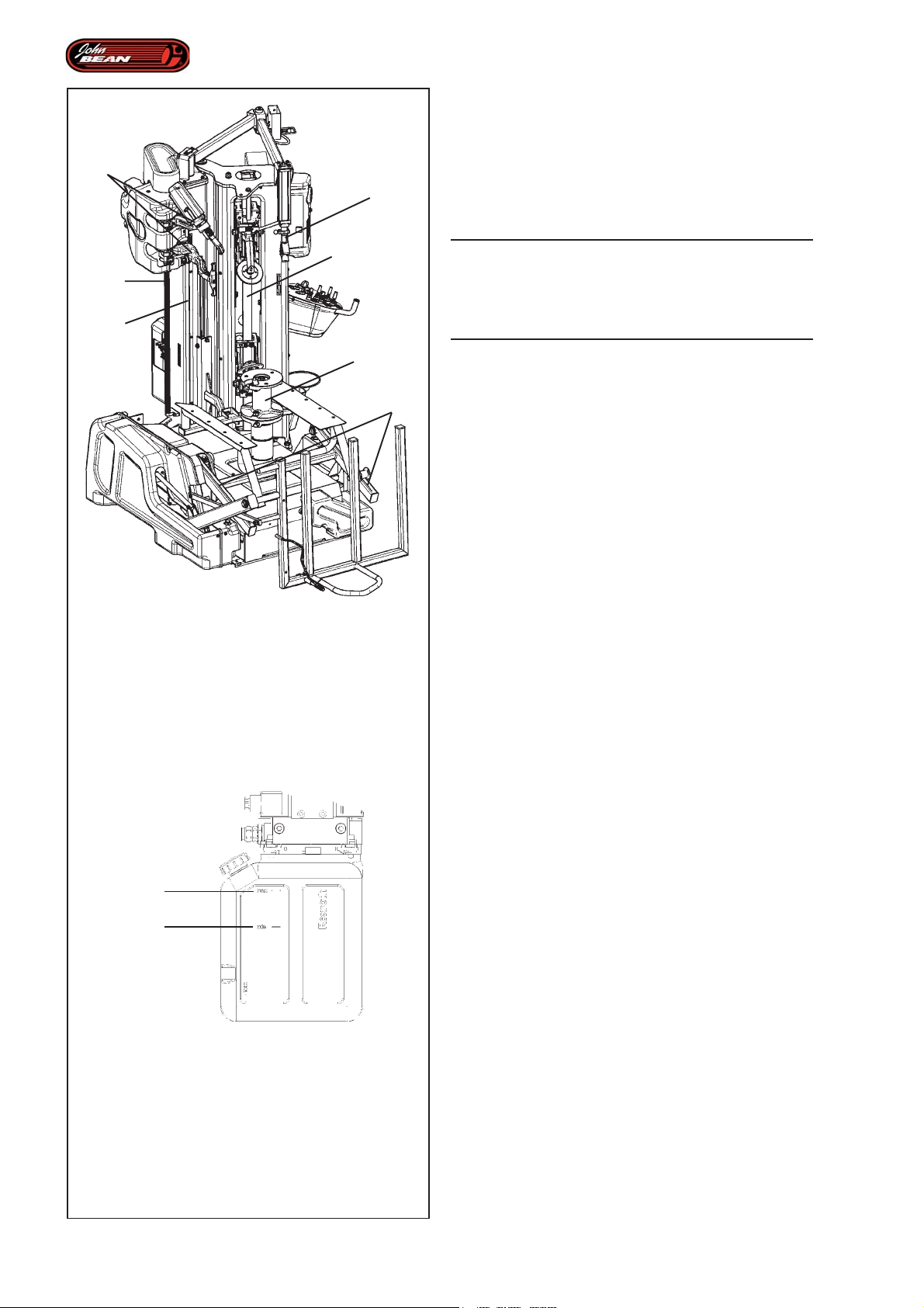
Maintenance
6.0 Maintenance
6
7
4
2
3
This tire demount unit will continue to provide maximum
working efficiency even after a long period of intensive
use as long as the operator carries out scheduled
maintenance as indicated below.
WARNING: BEFORE ATTEMPING ANY
MAINTENANCE OR REPAIRS THE MACHINE MUST
BE DISCONNECTED FROM THE ELECTRICAL
POWER SUPPLY AND THE COMPRESSED AIR
FEED LINE.
1
5
6.0-1
Every 6 months,
Arrange for the following to be carried out
• Check the various parts listed below for excessive
play and adjust if necessary (Call the technical service
center):
Figure 6.0-1
1) Wheel support.
2) Vertical activation bar on tools
3) Tool unit slide guides
4) Bead-breaker vertical slide guide
5) Lifter unit slide guides.
max
min
6.0-2
Every 4 months,
carry out:
• Removal of accumulated dirt with non-flammable
liquid detergent.
• Restoration, using a brush, of a suitable quantity of
oil for mechanical lubrication.
on the parts:
Figure 6.0-1
3) Tool unit slide guides
4) Bead-breaker vertical slide guide
5) Lifter unit slide guides
6) Automatic tool mobile parts and arms.
7) Bead pusher tool extraction rod.
• Check hydraulic oil level (Fig.6.0-2).
Note: Perform the check with all hydraulic cylinders closed.
To achieve this condition, position the parts as indicated
below:
- Bead breaking arms; touching in the central position
- Wheel clamping bar; right down.
If necessary add:
ESSO : Nuto H 46
SHELL : Tellus oil 46
TOTAL : Azolla 46
or equivalents.
92
Maintain a level close to "max".
Oil change is not required.
Operator’s Manual QUADRIGA 1000/BB
Page 93

Entretien
Wartung
6.0 Entretien
Un entretien périodique permet à l'opérateur de tirer un
maximum de profit de ce démonte-pneu et de le
conserver en bon état, y compris en cas d'usage
intensif.
ATTENTION : AVANT UN ENTRETIEN OU UNE
RÉPARATION, S'ASSURER QUE LA MACHINE EST
DEBRANCHEE DES CIRCUITS D'ALIMENTATION EN
ENERGIE ELECTRIQUE ET EN AIR COMPRIMÉ.
T ous les 6 mois,
Faire effectuer
• Vérifier l'absence de jeu et le cas échéant effectuer
le réglage (Faire appel à l'assistance technique)
sur les composants::
Figure 6.0-1
1) Porte-roue.
2) Barre d'actionnement vertical des Outils.
3) Glissières du Groupe Outils.
4) Glissière verticale des outils détalonneurs.
5) Glissières du Groupe d'Elévation.
6.0 Wartung
Diese Reifenmontiermaschine kann auch bei langer und
intensiver Arbeit höchste Effizienz gewährleisten, sofern
der Anwender die hier beschriebene Wartung
regelmäßig durchführt.
WARNUNG: VOR JEDER WARTUNG ODER
REPARATURARBEIT MUSS SICHERGESTELLT
WERDEN, DASS DIE MASCHINE VOM STROMNETZ
UND VON DER DRUCKLUFTZUFUHR GETRENNT IST.
Alle 6 Monate
Folgende Tätigkeiten vornehmen lassen
• Prüfen, ob das Spiel möglicherweise zu groß
geworden ist und gegebenenfalls regulieren (dazu den
technischen Kundendienst rufen)
An folgenden Teilen:
Abbildung 6.0-1
1) Radhalterung.
2) Vertikale Antriebsstange der Werkzeuge.
3) Gleitführungen der Werkzeugeinheit.
4) Vertikale Gleitführung der Wulstablöser.
5) Gleitführung der Hebereinheit.
T ous les 4 mois,
effectuer:
• Eliminer la saleté qui s'est accumulée, avec du savon
liquide non inflammable.
• Lubrifier les organes mécaniques avec un pinceau.
sur les composants:
Figure 6.0-1
3) Glissières du Groupe Outils.
4) Glissière verticale des outils détalonneurs.
5) Glissières du Groupe d'Elévation.
6) Bras et composants mobiles des Outils Automatiques.
7) Tige de glissement de l'outil presse-talon.
• Contrôle du niveau de l'huile hydraulique (Fig.6.0-2).
NB: Effectuer le contrôle avec les vérins hydrauliques
fermés.
Pour obtenir cette condition, placer les éléments
comme il est indiqué ci-dessous:
- Outils détalonneur ; au contact en position centrale
- Barre de Blocage Roue ; toute en bas.
Le cas échéant, faire l'appoint:
ESSO : Nuto H 46
SHELL : Tellus oil 46
TOTAL : Azolla 46
ou équivalents.
Maintenir un niveau proche du "max".
La vidange d'huile n'est pas demandée.
Alle 4 Monate
Folgende Tätigkeiten vornehmen:
• Den angesammelten Schmutz mit einem nicht
entzündbaren, flüssigen Reinigungsmittel entfernen.
• Mit einem Pinsel wieder genügend Öl auftragen, damit
die mechanische Schmierung gewährleistet ist.
An folgenden Teilen:
Abbildung 6.0-1
3) Gleitführungen der Werkzeugeinheit.
4) Vertikale Gleitführung der Wulstablöser.
5) Gleitführung der Hebereinheit.
6) Arme und bewegliche Teile der automatischen Werkzeuge.
7) Abzugstab für das Wulstniederhalterwerkzeug.
• Kontrolle des Hydraulikölstands (Abb.6.0-2).
Anmerkung: Bei dieser Kontrolle müssen die
Hydraulikzylinder geschlossen sein.
Um diesen Zustand zu erreichen, müssen die Elemente
folgendermaßen positioniert werden:
- Abdrückarme berühren einander in mittlerer Stellung.
- Radaufspannstab: ganz unten.
Falls nötig, folgendes Öl hinzufügen:
ESSO : Nuto H 46
SHELL : Tellus oil 46
TOTAL : Azolla 46
oder gleichwertige.
Der Ölstand sollte immer in der Nähe des maximalen
Füllstands ("max") liegen.
Manuel d’Utilisation QUADRIGA 1000/BBQUADRIGA 1000/BB
Betriebsanleitung
93
Page 94
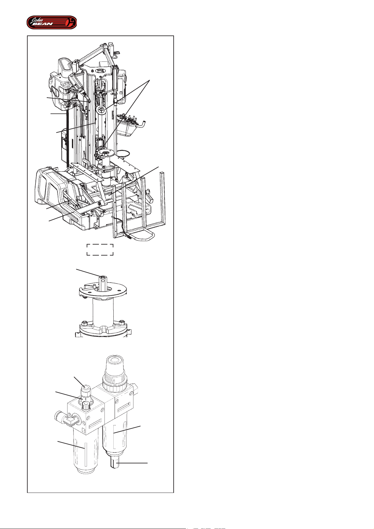
10
14
Maintenance
Every week,
carry out:
• Wash with cold water and soap or non-aggressive
chemical detergents.
11
2
13
12
9
6.0-1
• Dust only the bead breaking disks and tool guards
with talc.
on the parts:
Figure 6.0-1
9) Plastic guards for lifter parts
10) Plastic guards on mount/demount tool
11) Bead breaker disks
12) Plastic guard on wheel holder base.
Perform the following:
• Clean with a dry cloth
• Restore a thin film of protective oil
on the following parts:
-) Wheel clamping hub nut
13) Vertical slide cylinder rods on tools
14) Front lifter pneumatic cylinder rods
Figure 6.0-3
• Check that the lubrication unit is working properly.
One oil drop falling into the transparent cone G every
4-5 complete strokes of the bead breaker indicates
that the correct amount of oil is being dispersed in the
system. If necessary,
• Adjust the unit using the screw 'R' to correct the oil
flow so it is as indicated above.
G
T
15
R
6.0-2
Every day,
Perform the following:
• Clean with a dry cloth
the following parts:
Figure 6.0-1
10) Mount/demount tool plastic guards
11) Bead breaker disks
Perform the following:
• Clean with a dry cloth and compressed air.
the following parts:
Figure 6.0-2
15) Wheel clamping unit engage housing.
Figure 6.0-3
• Drain the water from the filter 'F' by pulling the fitting
'S' downwards.
• Check the level of oil in the lubricator.
F
94
S
6.0-3
Operator’s Manual QUADRIGA 1000/BB
Page 95

Entretien
Wartung
T outes les semaines,
effectuer:
• Laver avec de l'eau froide et du savon ou avec des
détergents chimiques non agressifs.
• Parsemer de talc les disques détalonneurs
uniquement et les protections outil.
sur les composants:
Figure 6.0-1
9) Protecteur en plastique pour les organes de l'élévateur
10) Protecteurs en plastique de l'outil de montage/
démontage.
11) Disque détalonneur
12) Protecteur en plastique de la base du Porte-Roue.
effectuer:
• Nettoyer avec un chiffon sec
• Remettre une fine couche d'huile de protection
sur les composants:
-) Ecrou de fixation roue
13) Tiges des cylindres de glissement vertical des outils
14) Tiges des vérins pneumatiques de l'élévateur frontal
Figure 6.0-3
• Contrôler le fonctionnement du graisseur.
Une goutte qui tombe dans le dôme transparent 'G'
toutes les 4-5 courses complètes de l'outil de
déjantage, indique que le système reçoit une juste
quantité d'huile. Le cas échéant,
• Régler l'unité en utilisant la vis 'R' pour corriger le
débit d'huile, comme il est indiqué supra.
T ous les jours,
effectuer:
• Nettoyer avec un chiffon sec
sur les composants:
Figure 6.0-1
10) Protecteurs en plastique de l'outil de montage/
démontage
11) Disques détalonneurs
effectuer:
• Nettoyage avec un chiffon et un jet d'air comprimé
sur les composants:
Figure 6.0-2
15) Logement pour l'accrochage du Groupe de Blocage
roue.
Figure 6.0-3
• Vidanger l'eau du filtre 'F' en tirant vers le bas la
vidange rapide 'S'.
• Contrôler le niveau d'huile dans le graisseur.
Einmal pro Woche,
Folgende Tätigkeiten vornehmen:
• Mit kaltem Wasser und Seife oder mit nicht
aggressiven chemischen Reinigungsmitteln reinigen.
• Nur die Wulstablösscheiben und die
Schutzvorrichtungen der Werkzeuge mit Talk
bestreuen.
An folgenden Teilen:
Abbildung 6.0-1
9) Kunststoffabdeckung für die Elemente der
Hebebühne.
10) Kunststoff-Schutzvorrichtungen des Montage-/
Demontagewerkzeugs
11) Wulstablösscheiben.
12) Kunststoffabdeckung des Fußes der Radhalterung
Folgende Tätigkeiten vornehmen:
• Mit einem trockenen Tuch reinigen
• Einen leichten Ölschutzfilm auftragen
An folgenden Teilen:
-) Radspannmutter
13) Schäfte der vertikalen Gleitzylinder der Werkzeuge
14) Schäfte der Pneumatikzylinder des Fronthebers
Abbildung 6.0-3
• Die Funktionstüchtigkeit der Schmiervorrichtung überprüfen.
Wenn alle 4 - 5 vollständige Umdrehungen des
Wulstablösers ein Tropfen in den durchsichtigen
Kegel ‚G' fällt, bedeutet das, dass die richtige Menge
an Öl an das System abgegeben wird,
• Die Einheit gegebenenfalls mit der Schraube ‚R' regulieren,
um den Ölfluss so einzustellen wie oben angegeben.
Täglich ,
Folgende Tätigkeiten vornehmen:
• Mit einem trockenen Tuch reinigen
An folgenden Teilen:
Abbildung 6.0-1
10) Kunststoff-Schutzvorrichtungen des Montage-/
Demontagewerkzeugs
11) Wulstablösscheiben
Folgende Tätigkeiten vornehmen:
• Mit einem trockenen Tuch und Druckluft reinigen.
An folgenden Teilen
Abbildung 6.0-2
15) Verbindungssitz für die Radaufspanneinheit.
Abbildung 6.0-3
• Das Wasser aus dem Filter ‚F' ablassen, indem
man den Schnellablass ‚S' nach unten zieht.
• Den Ölstand in der Schmiervorrichtung überprüfen.
Manuel d’Utilisation QUADRIGA 1000/BBQUADRIGA 1000/BB
Betriebsanleitung
95
Page 96
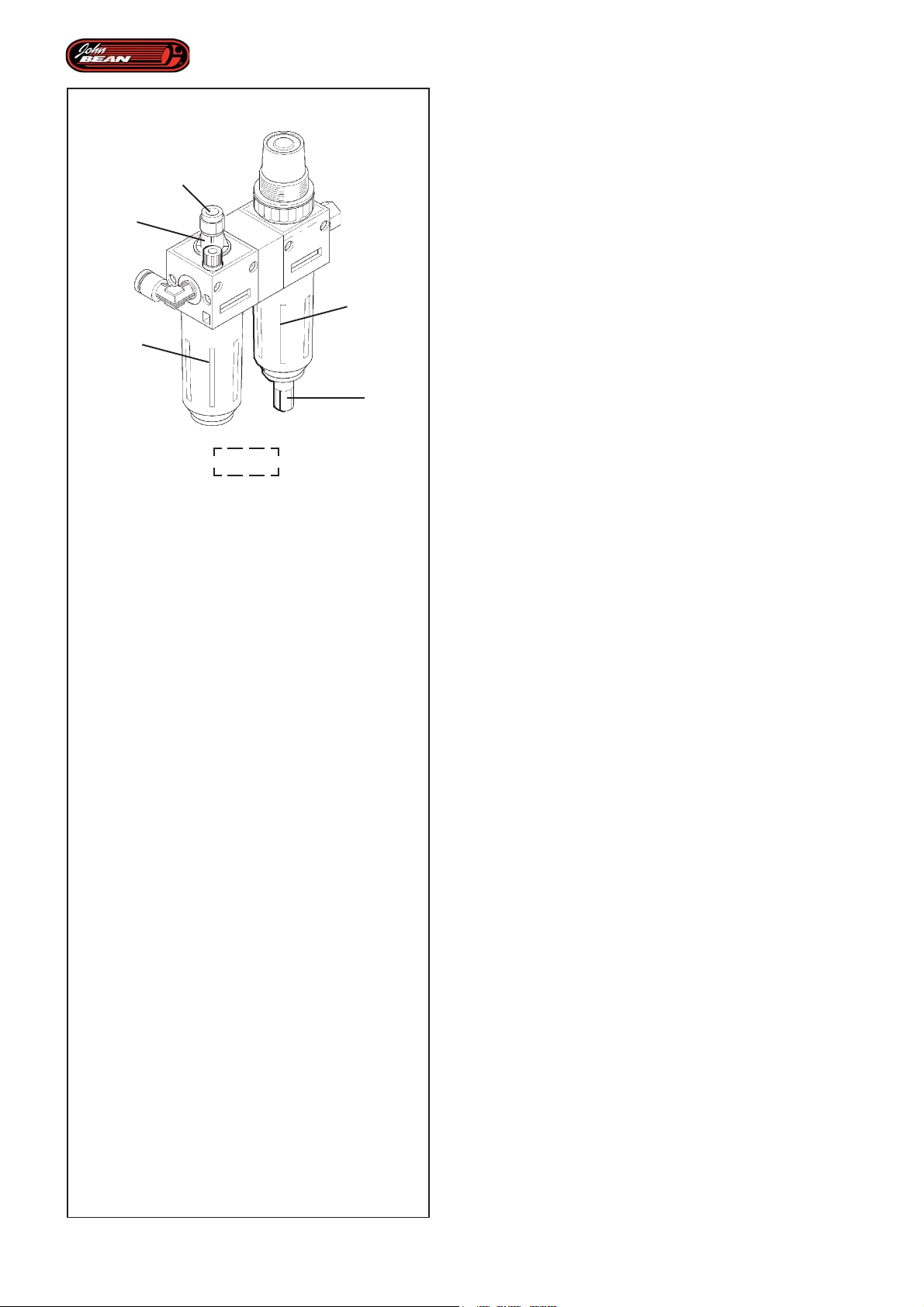
G
R
Maintenance
Oil top-up procedure in the lubricator:
• Detach the compressed air line.
• Remove the cup 'T' by rotating it.
• Add oil as required.
• Make sure that the gaskets are in position before
re-closing the cup.
USE ONLY OILS FOR AIR DEVICES, DO NOT USE
BRAKE FLUID OR OTHER NON-RECOMMENDED
LUBRICANTS.
T
6.0-3
F
S
Recommended oils for the filter/lubricator unit:
10W non-detergent / air tool oil.
If the machine is fitted with a tubeless inflator tank.
• Drain the condensation from the tank.
Note: The recommended repetition schedule for
the operations described are valid for normal
machine use.
We suggest you check and perform
extraordinary maintenance every time you
consider it necessary and in general, more
frequently than the time intervals indicated.
96
6.1 Storage
In case the machine is not to be used for a long period
of time (6 months or more) it is necessary to disconnect
all power sources, discharge the bead seater tank (for
models fitted with the Tubeless System GT), protect
all parts that may be damaged, protect the air hoses
that may be damaged by the drying process.
When putting the machine back in operation, check
first the condition of all previously protected parts, and
check for correct functioning of all devices before using
the machine again.
Operator’s Manual QUADRIGA 1000/BB
Page 97

Entretien
Wartung
Procédure d'appoint en huile dans le graisseur:
• Débrancher la ligne de l'air comprimé.
• Retirer le dôme 'T' en le tournant.
• Ajouter de l'huile.
• S'assurer que les joints sont en place avant de
refermer le verre.
UTILISER EXCLUSIVEMENT DES HUILES POUR
DISPOSITIFS PNEUMATIQUES, NE PAS UTILISER
DE LIQUIDE POUR FREINS OU AUTRES
LUBRIFIANTS NON PRECONISES.
Huiles préconisées pour le filtre/graisseur:
Huile non détergente 10W / Huile pour outils
pneumatiques.
Si la machine est équipée d'un réservoir pour le
pneumatique tubeless.
• Vidanger la condensation du réservoir.
Remarque: La périodicité des opérations a été calculée
en fonction d'un usage normal de la
machine.
Il est recommandé de contrôler la machine
et d'effectuer l'entretien, ordinaire et non, plus
fréquemment que la périodicité préconisée,
si celle-ci le requiert.
Vorgehen zum Nachfüllen von Öl in die
Schmiervorrichtung:
• Die Druckluftzufuhr abschalten.
• Das Absetzglas 'T' herausdrehen und abnehmen.
• So viel Öl wie nötig hinzufügen.
• Sicherstellen, dass die Dichtungen richtig sitzen,
bevor man das Glas wieder einsetzt.
ES DÜRFEN NUR ÖLE FÜR PNEUMATIKANLAGEN
VERWENDET WERDEN. KEINE
BREMSFLÜSSIGKEIT ODER ANDERE, NICHT
EMPFOHLENE SCHMIERMITTEL BENUTZEN.
Für den Filter/Luftöler empfohlene Öle:
10W nicht reinigendes Öl / Öl für Druckluftwerkzeuge.
Wenn die Maschine mit einem Druckluftbehälter zum
schlauchlosen Reifen ausgestattet ist.
• Das Kondenswasser aus dem Behälter ablassen.
Anmerkung: Die Häufigkeit der hier
beschriebenen Tätigkeiten bezieht
sich auf einen normalen Gebrauch der
Maschine.
Es wird empfohlen, die Maschine zu
überprüfen und die außerordentliche
Wartung vorzunehmen, sobald man
dies für nötig hält - auch häufiger als
hier angegeben.
6.1 Mise hors service
Dans le cas où la machine doit rester inutilisée pendant
longtemps (6 mois), il est nécessaire de débrancher
les sources d'alimentation en énergie et vider le réservoir
(pour les modèles équipés du système de GT). Veiller
à protéger les composants qui pourraient s'abîmer
comme les tuyaux pneumatiques qui pourraient s'abîmer
avec le temps (processus de dessèchement).
Au moment de remettre la machine en service, contrôler
tout d'abord le fonctionnement des composants
protégés et vérifier le fonctionnement de tous les
dispositifs.
Manuel d’Utilisation QUADRIGA 1000/BBQUADRIGA 1000/BB
6.1 Lagerung
Bei einer längeren Stilllegung der Maschine (6 Monate)
ist es notwendig, die Strom- und Luftzufuhr zu trennen,
den Tank zu leeren (bei Modellen, die mit dem System
zum schlauchloser Reifen ausgestattet sind) und
empfindliche Maschinenteile zu schützen, sowie die
Pneumatikschläuche zu schützen, die durch
Austrocknung beschädigt werden könnten.Vor der
Wiederinbetriebnahme die Leistungsfähigkeit der
geschützten Maschinenteile überprüfen und eine
Funktionsprüfung sämtlicher Vorrichtungen vornehmen.
Betriebsanleitung
97
Page 98

Trouble shooting
7.0 Troubleshooting.
If a problem with the tire changer should arise, proceed
in the following order to solve the problem:
1. Rethink the last steps taken.
Did you work according to the manual?
Did the unit work as described and expected?
2. Check the unit according to the list in this chapter.
3. Call your local sales agent for technical assistance.
The format of this section is:
Problem
1. Possible cause #1
• Possible solution(s)
2. Possible cause #2
• Possible solution(s)
Operating the turntable rotation pedal does not
cause any movement.
1. No electric power.
• Check that the electric plug is correctly inserted in
the mains socket and that the electric power supply
is on.
• Check that the main switch is ON.
2. Inverter, control device or motor short circuited.
• Check that the electrical requirements of the machine
are compatible with the power supply.
• Call the authorized service center for assistance.
The wheel does not stop turning.
1. The tools are putting too much pressure on the tire.
• Stop the operation and do not activate any
commands for at least 5 seconds.
• Lubricate the rim and the tire again.
The turntable rotation pedal does not return to
neutral position.
1. Switch spring is broken.
98
• Bring the switcher pedal to central position.
• Disconnect the machine from the electrical power
supply and the compressed air feed.
• Call the authorized service center for assistance.
Pneumatic controls hard.
1. No oil at valve rods.
• Check oil level and that lubricator is working properly
(see Maintenance Chapter).
Operator’s Manual QUADRIGA 1000/BB
Page 99

Dépannage
Fehlerbeseitigung
7.0 Dépannage.
En cas de problème avec le démonte-pneu, procéder
comme suit pour résoudre le problème:
1. Se remémorer les dernières actions effectuées.
Travaillez-vous conformément aux instructions du
manuel?
L’unité opère-t-elle correctement ?
2. Vérifier l’unité en suivant les indications de ce
chapitre.
3. Appeler le service assistance technique de votre
revendeur
Ce chapitre se divise en:
Problème
1. Cause possible #1
• Solution(s) possible(s)
2. Cause possible #2
• Solution(s) possible(s)
L'actionnement de la rotation de l'autocentrant
n'entraîne aucun mouvement
7.0 Fehlerbeseitigung
Sollte ein Problem mit der Reifenmontiermaschine
auftreten, gehen Sie bitte in der nachfolgend
beschriebenen Reihenfolge vor, um es zu lösen:
1. Versuchen Sie, sich an die letzten Schritte zu
erinnern, die sie durchgeführt haben.
Sind Sie in Übereinstimmung mit der Anleitung
vorgegangen?
Hat sich das Gerät wie beschrieben und
erwartet verhalten?
2. Überprüfen Sie das Gerät nach der in diesem Kapitel
angegebenen Liste.
3. Bitten Sie ihren örtlichen Vertreter um technischen
Kundendienst.
Diese Kapitel ist folgendermaßen aufgebaut:
Problem
1. Mögliche Ursache #1
• Mögliche Lösung(en)
2. Mögliche Ursache #2
• Mögliche Lösung(en)
Bei Betätigung der Drehung des Spanntellers
erfolgt keinerlei Bewegung.
1. Absence de de tension.
• Contrôler que la fiche soit branchée au réseau
électrique et que cette prise soit alimentée en
tension
• Contrôler que l'interrupteur principal soit éclairé.
2. Inverseur, centrale ou moteur en court-circuit.
• Contrôler que les caractéristiques électriques de la
machine soient compatibles avec celles de
l'installation.
• Appeler le centre d’assistance agréé.
La rotation de la roue s'interrompt.
1. Effort excessif des outils sur le pneu.
• Arrêter l'opération et n'activer aucune commande
pendant au moins 5 secondes.
• Lubrifier ultérieurement la jante et le pneu.
La pédale de rotation de l’autocentreur ne revient
pas en position centrale.
1. Ressort pédale cassé.
• Ramener la pédale inverseur en position centrale.
• Débrancher la machine du réseau électrique et
pneumatique.
• Appeler le service d’assistance agréé.
Commandes pneumatiques dures.
1. Manque d’huile au niveau des tiges des vannes
• Vérifier le niveau d'huile dans le lubrificateur et que
celui-ci fonctionne correctement (rubrique Entretien).
1. Es liegt keine Spannung an.
• Überprüfen, ob der Netzstecker in die entsprechende
Stromdose eingesteckt ist und ob diese Spannung
führt.
• Prüfen, ob der Hauptschalter eingeschaltet ist.
2. Kurzschluss am Wechselrichter, an der
Steuerzentrale oder am Motor.
• Überprüfen, ob die elektrischen Merkmale der Maschine
mit denen der Werkstattanlage vereinbar sind.
• Den Kundendienst rufen.
Das Rad hört auf sich zu drehen.
1. Zu starke Belastung der Werkzeuge am Reifen.
• Die Tätigkeit anhalten und mindestens 5 Sekunden
kein Steuer- oder Bedienelement aktivieren.
• Felge und Reifen noch einmal schmieren.
Das Steuerpedal für die Spanntellerdrehung kehrt
nicht in die Mittellage zurück.
1. Pedalfeder defekt.
• Steuerpedal in die Mittellage zurückführen.
• Strom-und Luftzufuhr abschalten.
• Den Kundendienst rufen.
Steuerungen für harte Reifen.
1. Kein Öl erreicht das Ventilgestänge.
• Den Schmierölstand und die Funktionstüchtigkeit
der Schmiervorrichtung überprüfen (siehe Kapitel
"Wartung").
Manuel d’Utilisation QUADRIGA 1000/BBQUADRIGA 1000/BB
Betriebsanleitung
99
Page 100

Trouble shooting
Bead breaker cylinder lacks power during bead
breaking.
1. Low air pressure.
• Check air pressure of feed.
2. Cylinder seals worn.
3. Faulty valve
• Check oil level and make sure lubricator is working
properly as described in Maintenance chapter
• Call the authorized service center for assistance.
Machine damages alloy rims.
1. Plastic tool guard worn.
• Replace the plastic tool guard.
2. Tool is at wrong distance from rim.
• Call the authorized assistance service.
Irregular movement of bead pusher arm.
Wheel lifter jammed.
1. Low air pressure.
• Check air line pressure.
2. Control cylinder defective.
• Call the authorized service center for assistance.
3. Control valve defective.
• Check oil level in the lubrication device and that latter
is working properly as described in the Maintenance
chapter.
• Call the authorized service center for assistance.
The Front Lifter does not move up.
1. The diameter of the wheel is not large enough to
activate the upstroke movement enable sensor.
• Place the wheel on the Wheel Holder Flange
manually.
2. The wheel diameter reading sensor is faulty.
• Call the authorized service center for assistance.
100
Operator’s Manual QUADRIGA 1000/BB
 Loading...