

John Bean BFH 1000, BFH 1000 Super Operation Instructions Manual
COMPUTER RIDE DIAGNOSTIC
WHEEL BALANCER
BFH 1000 and BFH 1000 Super
EEWB519A and EEWB519S
OPERATION INSTRUCTIONS
Form ZEEWB519A rev C July, 2006

Blank page

SAFETY INFORMATION
For your safety, read this manual thoroughly
before operating the BFH 1000 or BFH 1000 Super Wheel Balancers
The JBC BFH 1000 and BFH 1000 Super Ride Diagnostic Wheel Balancers are intended for use by properly trained automotive technicians. The safety messages presented in this section and throughout the manual are reminders to the operator to exercise extreme caution when servicing tires with these products.
There are many variations in procedures, techniques, tools, and parts for balancing
tires, as well as the skill of the individual doing the work. Because of the vast number of
wheel and tire applications and potential uses of the product, the manufacturer cannot
possibly anticipate or provide advice or safety messages to cover every situation. It is
the automotive technician's responsibility to be knowledgeable of the wheels and tires
being serviced. It is essential to use proper service methods in an appropriate and
acceptable manner that does not endanger your safety , the safety of others in the work
area or the equipment or vehicle being serviced.
It is assumed that, prior to using the BFH 1000 or BFH 1000 Super Ride Diagnostic
Wheel Balancer, the operator has a thorough understanding of the wheels and tires
being serviced. In addition, it is assumed he has a thorough knowledge of the operation
and safety features of the rack, lift, or floor jack being utilized, and has the proper hand
and power tools necessary to service the vehicle in a safe manner.
Before using the BFH 1000 or BFH 1000 Super Ride Diagnostic Wheel Balancer,
always refer to and follow the safety messages and service procedures provided by the
manufacturers of the equipment being used and the vehicle being serviced.
IMPORTANT !! SAVE THESE INSTRUCTIONS -- DO NOT DISCARD !!
I

IMPORTANT SAFETY INSTRUCTIONS
When using this equipment, basic safety precautions should always be followed, including the
following:
1. Read all instructions.
2. Do not operate equipment with a damaged power cord or if the equipment has been
damaged - until it has been examined by a qualified authorized service technician.
3. If an extension cord is used, a cord with a current rating equal to or more than that
of the machine should be used. Cords rated for less current than the equipment
may overheat. Care should be taken to arrange the cord so that it will not be tripped
over or pulled.
4. Always unplug equipment from electrical outlet when not in use. Never use the
cord to pull the plug from the outlet. Grasp plug and pull to disconnect.
5. To reduce the risk of fire, do not operate equipment in the vicinity of open
containers of flammable liquids (gasoline).
6. Keep hair, loose fitting clothing, fingers and all parts of the body away from moving
parts.
7. Adequate ventilation should be provided when working on operating internal
combustion engines.
8. To reduce the risk of electric shock, do not use on wet surfaces or expose to rain.
9. Do not hammer on or hit any part of the control panel with weight pliers.
10. Do not allow unauthorized personnel to operate the equipment.
11. Do not disable the hood safety interlock system or bypass the intended operation.
12. Use only as described in this manual. Use only manufacturer’s recommended
attachments.
13. Always make sure the power clamp is sucure before spinning the shaft.
14. ALWAYS WEAR SAFETY GLASSES. Everyday eyeglasses only have impact
resistant lenses, they are NOT safety glasses.
15. Balancer is for indoor use only.
16. This equipment uses class II lasers. Do not look into or allow by standers to look into the
laser source.
SAVE THESE INSTRUCTIONS
II

Contents
SAFETY INFORMATION ...................................................................................................................1
1.0 INTRODUCTION .........................................................................................................................1
1.1 SAFETY NOTICE.........................................................................................................................2
1.2 BALANCER APPLICA TION..........................................................................................................2
1.3 BFH 1000 SPECIFICATIONS .....................................................................................................2
1.4 FEATURES ...................................................................................................................................3
1.5 STANDARD ACCESSORIES .......................................................................................................4
1.6 OPTIONAL ACCESSORIES........................................................................................................5
1.6 PRE-INSTALLATION CONSIDERATIONS .................................................................................5
1.7 DIMENSIONS OF THE MACHINE ..............................................................................................5
1.8 INSTALLATION AREA REQUIREMENTS...................................................................................6
1.9 INSTALLATION PRECAUTIONS ................................................................................................6
2.1 ELECTRIC INSTALLATION.........................................................................................................7
2.2 SETUP ..........................................................................................................................................7
2.2.2 CUSTOMIZING OPTIMA FEATURES ..................................................................................... 9
3.0 Physical Layout..........................................................................................................................9
3.1 The Display Screen ....................................................................................................................9
3.2 Menu Keys.................................................................................................................................10
3.2.2 MAIN MENU FUNCTIONS ....................................................................................................11
3.2.3 BALANCING ........................................................................................................................... 11
3.2.8 FUNCTION (SETUP) .............................................................................................................13
4.0 Help information .......................................................................................................................14
5.0 POWER CLAMP.........................................................................................................................15
6.0 OPERATION OF THE BALANCER ........................................................................................... 16
6.1 CHECK LIST - INSPECTION................................................................................................... 16
6.2 BALANCE SCREEN DESCRIPTION ....................................................................................... 17
6.2.1 WHEEL MOUNTING..............................................................................................................18
6.2.2 STANDARD WHEELS (BACK CONE MOUNT) ...................................................................18
6.2.3 CENTERING LIGHT-TRUCK WHEELS ................................................................................18
6.3 SCAN MODE SELECTION ........................................................................................................ 19
6.4 SPINNING THE WHEEL............................................................................................................20
6.5 SELECTING THE WEIGHT PLACEMENT ..............................................................................20
6.6 CORRECTION OF THE IMBALANCE...................................................................................... 21
6.6 PROCEDURE WHEN SCANNER FAILS TO ACQUIRE A VALID PROFILE ............................21
6.7 VERIFICATION OF THE RESULTS.......................................................................................... 21
6.8 VIBRATION PROBLEMS .........................................................................................................22
7.0 SPOKE BALANCING MODE.....................................................................................................22
8.0 BFH 1000 Procedures ............................................................................................................23
8.2 Begin Diagnostic Run .............................................................................................................23
8.2 Profiling the wheel....................................................................................................................23
8.3 BFH 1000 Geometric Matching.............................................................................................. 25
8.4 Bare Rim Diagnosis .................................................................................................................27
9.0 OptiLine, Balancing a Set of Wheels ....................................................................................28
9.1 OptiLine Customer Calibration ..............................................................................................31
9.0 USER CALIBRATION ................................................................................................................33
10.0 EXPLANATION OF PROGRAM CODES ................................................................................34
11.0 MAINTENANCE........................................................................................................................36
12.0 TROUBLE SHOOTING ...........................................................................................................36


John Bean BFH 1000 Series Operators Manual
1.0 INTRODUCTION
Congratulations on purchasing the BFH 1000 Series Computer Ride Diagnostic Wheel Balancer. This wheel balancer is designed for ease of operation, accuracy , reliability and speed. With proper maintenance and care your
wheel balancer will provide many years of trouble-free operation.
BFH Ride Diagnostics Balancer - Precautions T o Observe
Y our BFH 1000 Series Ride Diagnostics Balancer utilizes the latest in electronics and instrumentation technology ,
incorporating three separate scanning lasers along with an embedded computer (PC). Following the precautions
listed below will help to ensure continuous and satisfactory operation of your unit.
1) Install the balancer on a dedicated power line in order to avoid electrical noise and power line fluctuations.
Avoid power cord length greater that 15 feet.
2 ) The BFH1000 Series Ride Diagnostic Wheel Balancer utilizes red scanning lasers which actually create an
image of the wheel being diagnosed. Install the balancer away from direct sunlight so that the laser beams can
be detected by the scanner. Avoid placing high intensity lamp s and infrared heaters near the BFH balancer.
3) Diagnose and balance only those wheels which fit within the specifications of the BFH Balancer:
Rim width = 3 - 20 inches
Rim diameter = 8 - 30 inches
Max tire diameter = 44 inches
Minimum distance required from cabinet to rim edge = 56 mm (2.20 inches) for wheel sizes 13-18 inches in
diameter.
Minimum distance required from cabinet to rim edge = 81 mm (3.19 inches) for wheel sizes 19-24 inches in
diameter.
4) The BFH balancer is designed to properly scan the profile of existing rims. Extreme geometric combinations
of rim diameter and flange offset can inhibit the proper viewing of the rim profile. These exceptional rims can
be properly balanced by manually entering the distance, diameter, and wid th of the rim.
5) The wheel guard of the BFH1000 Series Ride Diagnostic Wheel Balancer also serves as the housing for one of
the scanning lasers. Since the laser must remain stationary once the spin cycle begins, do not lean on or
otherwise disturb the wheel guard until the spin cycle has been completed.
Instructions on use, operational requirements and routine maintenance of the machine are covered in this manual.
This unit uses an open source Linux operating system for its user interface. This open source code is available
for the cost of shipping and handling to owners of the BFH1000 Series Ride Diagnostic Wheel Balancer.
Requests must be made to the attention of balancer product management at the Conway AR address listed on
the back of this manual. Please include the owners name, address and unit serial number with all requests.
STORE THIS MANUAL IN A SAFE PLACE FOR FUTURE REFERENCE.
READ THIS MANUAL THOROUGHLY BEFORE USING THE MACHINE.
Page 1

1.1 SAFETY NOTICE
This manual is a part of the balancer product.
Read carefully all warnings and instructions of this manual since they provide important information concerning
safety and maintenance.
1.2 BALANCER APPLICATION
The John Bean BFH1000 Series Ride Diagnostic Wheel Balancer is intended to be used as a device to balance,
diagnose and correct car, and light truck wheel vibration problems within the following range:
Maximum tire diameter : 44” (1 117mm)
Maximum wheel diameter : 30” (762mm)
Maximum wheel wid th : 20” (381mm)
Maximum wheel weight : 154 lbs (70 kg)
This device is to be only used in the application for which it is specifically designed.
Any other use shall be considered as improper and thus not reasonable.
The manufacturer shall not be considered liable for possible damages caused by improper, wrong or non reasonable use.
1.3 BFH 1000 SPECIFICATIONS
Weight Imbalance Accuracy .05 oz / 1 gram
Weight Placement Resolution ± .7 degrees
Weight Imbalance Resolution:
Roundoff Mode .25 oz / 5 grams
Non-Roundoff Mode .05 oz / 1 gram
Max. Shaft Weight Capacity 154 lbs / 70 kg
Max.Tire Diameter 44" / 1117 mm
Rim Width Capacity 3.0"-20" / 76 mm - 508 mm
Max. Tire Width 21” / 530 mm
Rim Diameter Capacity 8"-30"/203mm-762mm
Balancing Cycle Time (normal mode) 20 seconds or less
Shaft Speed at calculation >200 RPM
Electrical 230vac, 1ph, 50-60Hz, 3.2A
Required Work Area 64” x 64” (1626 x1626 mm)
Shipping Weight, complete 645 lbs/293kg
Shipping Dimensions 72"L X 73"W X 63"D (1829x1854x1600mm)
Machine Dimensions 64”h 64”w 64”d (1626x1626x1626mm)
Actual Weight with Accessories 550 lbs
Operating T emperature Range 32-122F / 0-50C
Page 2

John Bean BFH 1000 Series Operators Manual
1.4 FEATURES
• Self test check with every power up cycle.
• Selectable car/light truck limit values
• Advanced Spoke count capability
• Rim-only diagnostics
• Rim cleaning brake control
• Flat spot detection
• On-board diagnostics for easy service issues
• Selectable default weight placement mode
• Advanced Help screens with illustrations
• Pre-programmed Error Codes indicate procedural errors or safety concerns.
• Fully Automatic All-Parameter Data Entry .
• Fully Automatic Rim/Tire Profiling.
• Fully Automatic S poke/S plit W eight Function for Hidden Weight Placement.
• Fully Automatic Lef t and Right Radial & Lateral Runout Measurements.
• Bare Rim Radial and Lateral Runout Measurement
• Tire Tread Depth Measurement.
• Hands-Free Power Clamping for Precise Wheel Placement.
• Fast Tire/Wheel Diagnostic System Time, Floor-to-Floor .
• Captured back spring eliminates having to handle the backing spring.
• Automatic recalculation if weight positions are changed. No need for re-spinning the wheel.
• Common 40 mm diameter mounting shaft.
• Easy-to-Read LCD Data Display Monitor .
• Dynamic and single weight Static cap ability.
• Stop-at-Top features simplifies weight imbalance location
• Automatic Weight T ype Selection Based on Rim Profile, Indicated by Color Coded Icons
• Optima Balance feature for reducing weight required.
• Built-in spin counter for monitoring balancer productivity .
• Service code access to all Balancer electronic functions for fast, easy diagnosis.
• Operator selectable round-off mode.
• Wheel pull index, option (standard on BFH 1000 Super)
• Wheel runout in multiple positions, optional feature (standard on BFH 1000 Super)
• Premium 7 cone set with storage tray option (standard on BFH 1000 Super)
Page 3
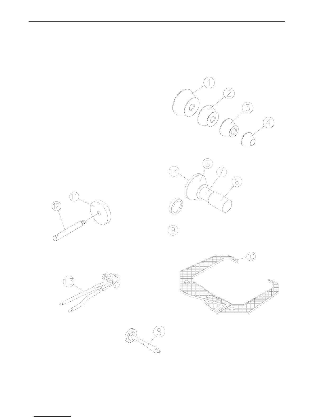
1.5 STANDARD ACCESSORIES
Standard accessories ( Figure 1) included with the S tandard BFH 1000 are:
1 EAM0003J08A Cone, 85-132 mm / 3.3”-5.2”
2 EAM0003J07A Cone, 71-99 mm / 2.8”-3.9”
3 EAM0003J06A Cone, 56-84 mm / 2.2”-3.3”
4 EAM0003J05A Cone, 43-63 mm / 1.7” - 2.5”
5 EAC0058D07A Cup - Large Pressure
6 EAM0005D54A Plastic Sleeve
7 EAA0283D53A Power Clamp Nut
8 EAM0005D40A Weight - Shaft Calibration
9 EAC0058D08A Small Presure Disk
10 EAA0247G21A Caliper - Rim Width
11 EAC0060G02A Flange - Cover, Hook
12 EAM0006G01A Pin - Accessory
13 58839 Weight Pliers
14 EAC0058D15A Soft Protective Ring
Figure 1
Page 4
John Bean BFH 1000 Series Operators Manual
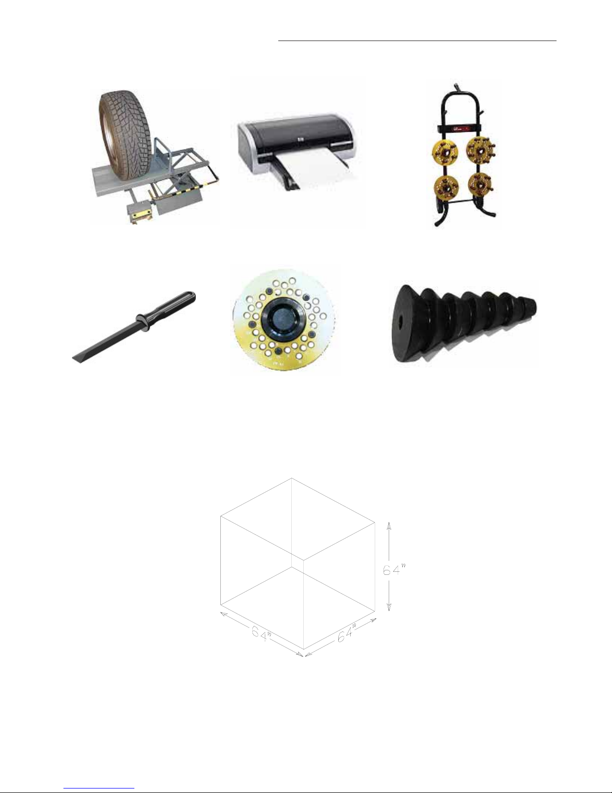
1.6 OPTIONAL ACCESSORIES - SEE FIGURE 2
Wheel Lift - EAK0221J27A Printer Kit - EAK0221J26A Flange Plate Cart
EAS2081J30A
Stick-on W eight Removal T ool Flange Plates - Kit of 4 7 Cone Set - EAK0221J31A
EEHT300A EAK0221J22A (Standard with BFH Super)
Figure 2
PRE-INSTALLATION CONSIDERATIONS
1.7 DIMENSIONS OF THE MACHINE
EAM0003J64 – 1.70" T0 2.23" Cone
EAM0003J65 – 2.03" T0 3.17" Cone
EAM0003J66 – 2.38" T0 3.51" Cone
EAM0003J67 – 2.74" T0 3.87" Cone
EAM0003J68 – 3.08" T0 4.21" Cone
EAM0003J69 – 3.42" T0 5.40" Cone
EAM0003J70 – 4.21" T0 6.30" Cone
Figure 3 - Footprint Requirements
Page 5
1.8 INSTALLATION AREA REQUIREMENTS
Make sure that from the operating position the user can see all of the machine and the surrounding area.
The operator should prevent non authorized persons and/or objects from entering the area which may create
potential hazards.
The machine should be installed on a stable level floor . Do not inst all the machine on a uneven floor.
If the balancer is to be installed on a raised floor, the floor must have a cap acity of at least 1 10lbs per sq ft. (5000
N/m² - 500 kg/m²).
It is not required to secure the machine to the floor but is recommended.
Install the machine in a dry , covered area.
The installation of the machine requires a working area of at least 64” x 64” (1626 x1626 mm). See Figure 3
1.9 INSTALLATION PRECAUTIONS
CAUTION! CAREFULL Y REMOVE THE BALANCER FROM THE PALLET.
Remove the hardware that secures the machine to the pallet and slide the balancer onto the floor where it is
to be installed.
THE UNIT IS HEA VY AND THE WEIGHT IS NOT EVENLY DISTRIBUTED.
DO NOT LIFT THE BALANCER BY THE SHAFT OR WHEEL GUARD FRAME.
DROPPING THE UNIT MA Y CAUSE PERSONAL INJURY OR EQUIPMENT DAMAGE.
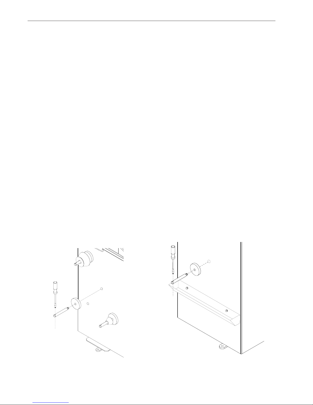
2.0 INSTALL ACCESSORY PINS
A. Install the accessory pins (Figures 4a and 4b). T ighten firmly .
B. Install the Cone Accessory tray if installing a BFH 1000 Super Model. See Figure 4b.
Figure 4a - BFH 1000
C. Place accessories onto the accessory pins or place 7 cone set into tray if installing a BFH 1000 Super.
Figure 4b - BFH 1000 Super
Page 6
John Bean BFH 1000 Series Operators Manual
2.1 ELECTRIC INSTALLATION
ANY ELECTRICAL WIRING MUST BE PERFORMED BY LICENSED PERSONNEL.
ALL SERVICE MUST BE PERFORMED BY AN AUTHORIZED SERVICE TECHNICIAN.
Check on the plate of the machine that the electrical specifications of the power source are the same as the
machine. The machine uses 230V AC (+/- 15%), 50-60Hz, 1Ph, 3.2 Ampere.
NOTE:
ANY ELECTRICAL OUTLET INST ALLA TION MUST BE VERIFIED BY A LICENSED ELECTRICIAN BEFORE
CONNECTING THE BALANCER.
NOTE:
THIS MACHINE PERFORMS A SELF-TEST ROUTINE ON START-UP. THERE WILL BE A DELAY OF SEVERAL MOMENTS BEFORE UNIT IS READY FOR OPERATION. ANY PROBLEMS DETECTED AT STARTUP WILL RESUL T IN THE DISPLAY OF AN ERROR CODE. PROBLEMS DETECTED DURING OPERA TION
ARE SA VED T O A LOG FILE WHICH CAN BE RETRIEVED FOR DIAGNOSIS BY A TECHNICIAN.
2.2 SETUP
Every shop has different procedural requirements meaning each machine should be customized to the unique
services performed at that location. Most attributes are set from the Main Function menu. A second “Optima”
menu allows further customization
2.2.1 Customizing the System
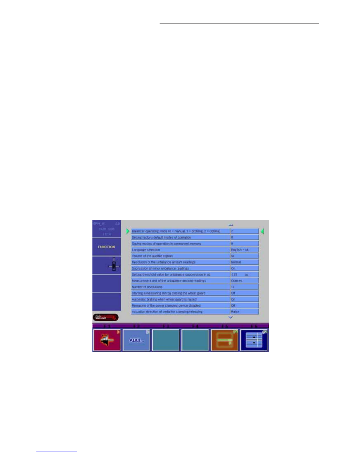
A. Select the “Function” key (F1) from the “Welcome” menu. The Main Function setup screen appears as in
Figure 5.
Figure 5
B. Press and hold the “F6” button and rotate the wheel to scroll up or down to the desired line item.
C. Press and hold the “F5” button and rotate the wheel to change selected topic to desired value or function.
D. When the desired features have been selected, save selections to permanent memory by selecting line item “3”.
Hold the F5 button while rotating the shaft, enter a value of “1”, release to Save to Permanent Memory. See
Figure 5a next page for complete menu listing.
E. Select the “ESC” button on the keyboard to return to the main screen.
Page 7

Figure 5a - Complete Function Menu listing
Page 8
 Loading...