

Page 1

Reference manual
Temperature Calibrator
Jofra ETC-125 A / 400 A / 400 R
Find Quality Products Online at: [email protected]
www.GlobalTestSupply.com
Page 2

User- and Reference manual
Temperature Calibrator
JOFRA ETC-125 A / 400 A / 400 R
Copyright 2005 AMETEK Denmark A/S (123943-UK)
Find Quality Products Online at: [email protected]
www.GlobalTestSupply.com
Page 3

Page 4

considerable personal injury or material damage.
attention.
About this manual….
• The structure of the user- and reference manual
The user manual sets out the operating instructions for the
instrument. It is designed to provide a quick reference guide for
use in the field.
The reference manual is aimed at users who are familiar with
AMETEK calibrators, as well as those who are not. The manual
is divided into 10 chapters which describe how to set up,
operate, service and maintain the calibrator. The technical
specifications are described and accessories may be ordered
from the list of accessories.
• Safety symbols
is manual contains a number of safety symbols designed to
Th
draw your attention to instructions which must be followed when
using the instrument, as well as any risks involved.
Warning
Conditions and actions that may compromise the
safe use of the instrument and result in
Caution…
Conditions and actions that may compromise the
safe use of the instrument and result in slight
personal or material damage.
Note…
Special situations which demand the user’s
123943 08 2019-04-12
Find Quality Products Online at: [email protected]
www.GlobalTestSupply.com
Page 5

List of contents
................................................. User manual, English
........................................ Reference manual, English
2019-04-12 123943 08
Find Quality Products Online at: [email protected]
www.GlobalTestSupply.com
Page 6

User manual
Temperature Calibrator
JOFRA ETC-125 A / 400 A / 400 R
Copyright 2005 AMETEK DENMARK A/S (123943-UK)
Find Quality Products Online at: [email protected]
www.GlobalTestSupply.com
Page 7

Page 8

FIG. 1
1
N
O
115 V
2
5
3 4
2019-04-12
Find Quality Products Online at: [email protected]
www.GlobalTestSupply.com
Page 9
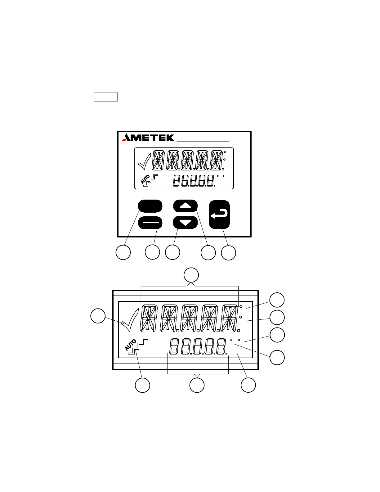
FIG. 2
14
CALIBRATION INSTRUMENTS
AUTO
STEP
ESC
MENU
5
4
3
6
2
C
min
C
F
F
1
ETC
C
F
7
8
9
F
C
min
10
1213
2019-04-12
Find Quality Products Online at: [email protected]
www.GlobalTestSupply.com
11
Page 10
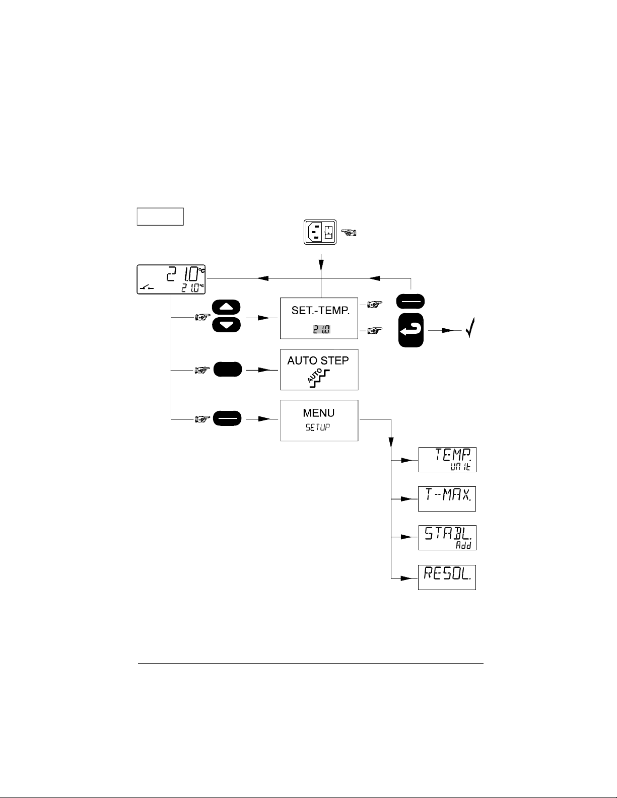
FIG. 3
AUTO
STEP
ESC
MENU
ESC
°C
°C
MENU
2019-04-12
Find Quality Products Online at: [email protected]
www.GlobalTestSupply.com
Page 11
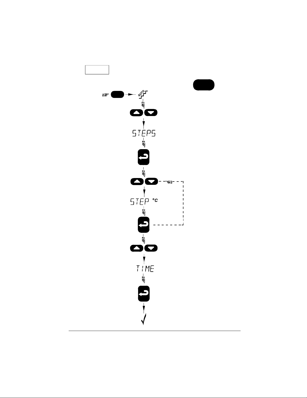
FIG. 4
AUTO
STEP
AUTO
STEP
2019-04-12
Find Quality Products Online at: [email protected]
www.GlobalTestSupply.com
Page 12
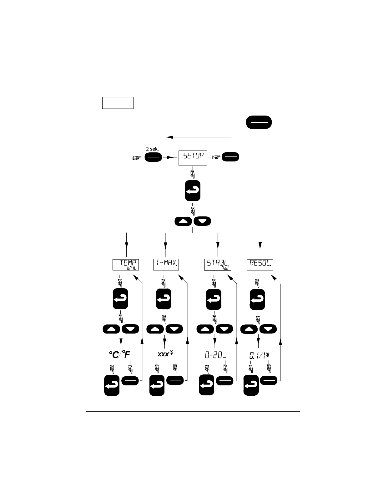
FIG. 5
ESC
MENU
ESC
MENU
ESC
MENU
ESC
MENU
ESC
MENU
ESC
MENU
ESC
MENU
2019-04-12
Find Quality Products Online at: [email protected]
www.GlobalTestSupply.com
Page 13

List of contents
1.0 Introduction ..................................................................... 2
2.0 Safety instructions ......................................................... 3
3.0 Operating the calibrator ................................................. 7
3.1 Before use ......................................................................... 7
3.2 Keyboard ......................................................................... 10
3.3 Display ............................................................................ 10
3.4 Connections .................................................................... 11
3.5 Calibrator functions - overview......................................... 11
3.6 Selecting the set-temperature .......................................... 11
3.7 AUTO STEP ............................................
3.8 MENU .............................................................................. 13
4.0 After use ........................................................................ 14
4.1 Switching off the calibrator ............................................... 15
........................ 12
123943 08 1
Find Quality Products Online at: [email protected]
www.GlobalTestSupply.com
Page 14

1.0 Introduction
ETC-calibrators are temperature calibrators designed to calibrate
temperature sensors.
Read this manual carefully before using the instrument and make
sure that all safety instructions and warnings are observed.
2 123943 08
Find Quality Products Online at: [email protected]
www.GlobalTestSupply.com
Page 15

2.0 Safety instructions
Read this manual carefully before using the
instrument!
In order to avoid any personal injuries and/or damage to
the instrument all safety instructions and warnings must be
observed.
Disposal – WEEE Directive
These calibrators contain Electrical and Electronic circuits
and must be recycled or disposed of properly (in
accordance with the WEEE Directive 2002/96/EC).
Warning
About the use:
• The calibrator mu
than those described in this manual, as it might cause a
hazard.
• The calibrator has been designed for indoor use only
and is not to be used in wet locations.
• The calibrator is not to be used in hazardous areas,
where vapour or gas leaks, etc. may constitute a
danger of explosion.
• The calibrator is not designed for operation in altitudes
above 2000 meters.
• The calibrator is a CLASS I product and must be
connected to a mains outlet with a protective earth
connection. Ensure the ground connection of the
calibrator is properly connected to the protective earth
before switching on the calibrator. Always use a mains
power cable with a mains plug that connects to the
protective earth.
st not be used for any purposes other
123943 08 3
Find Quality Products Online at: [email protected]
www.GlobalTestSupply.com
Page 16

• To ensure the connection to protective earth any
extension cord used must also have a protective earth
conductor.
• Only use a mains power cord with a current rating as
specified by the calibrator and which is approved for the
voltage and plug configuration in your area.
• Before switching on the calibrator make sure that it is
set to the voltage of the mains electricity supply.
• Always position the calibrator to enable easy and quick
disconnection of the power source (mains inlet socket).
• The calibrator must be kept clear within an area of 20
cm on all sides and 1 metre above the calibrator due to
fire hazard.
• Never use heat transfer fluids such as silicone, oil,
paste, etc. in the calibrators. These fluids may
penetrate the calibrator and cause electrical hazard,
damage or create poisonous fumes.
• The calibrator must be switched off before any attempt
to service the instrument is made. There are no user
serviceable parts inside the calibrator.
• When cleaning the well or insertion tube, REMEMBER
to wear goggles when using compressed air!
About the insertion tubes and well:
• Never leave hot insertion tubes which have been
emoved from the calibrator unsupervised – they may
r
constitute a fire hazard or personal injury.
• If you intend to store the calibrator in the optional
aluminium carrying case after use, you must ensure that
the instrument has cooled down to a temperature below
100°C/212°F before placing it in the carrying case.
• Never place a hot insertion tube in the optional carrying
case.
4 123943 08
Find Quality Products Online at: [email protected]
www.GlobalTestSupply.com
Page 17

Caution – Hot surface
• Do not touch the well, the insertion tube or the grid
plate, as the calibrator is heating up / has been heated
up – they may be very hot and cause burns.
• Do not touch the tip of the sensor when it is removed
from the insertion tube/well – it may be very hot and
cause burns.
• Over 50°C/122°F
If the calibrator has been heated up to temperatures
above 50°C/122°F, you must wait until the instrument
reaches a temperature below 50°C/122°F before you
switch it off.
• Do not remove the insert from the calibrator before the
insert has cooled down to less than 50°C/122°F.
Caution – Cold surface
Below 0°C/32°F (applies only to the ETC-125 A models)
• Do not touch the well or insertion tube when these are
below 0°C/32°F - they might create frostbite.
• If the calibrator has reached a temperature below
0°C/32°F, ice crystals may form on the insertion tube
and the well. This, in turn, may cause the material
surfaces to oxidize
To prevent this from happening, simply heat up the
calibrator to 100°C/212°F until all water left has
evaporated.
It is very important that humidity in the well and insertion
tube is removed to prevent corrosion and frost
expansion damages.
123943 08 5
Find Quality Products Online at: [email protected]
www.GlobalTestSupply.com
Page 18

Caution…
About the use:
• Do not use the instrument if the fan is out of order.
• Before cleaning the calibrator, you must switch it off,
allow it to cool down and remove all cables.
About the well, insertion tube and grid plate:
• The well and the insertion tube must be clean before
use.
• Do not pour any form of liquids into the well. It might
damage the well or cause a hazard.
• Scratches and other damage to the insertion tubes
should be avoided by storing the insertion tubes
carefully when not in use.
• The insertion tube must never be forced into the well.
The well could be damaged as a result, and the
insertion tube may get stuck.
• The insertion tube must always be removed from the
calibrator after use.
The humidity in the air may cause corrosion oxidation
on the insertion tube inside the instrument. There is a
risk that the insertion tube may get stuck if this is
allowed to happen.
Note…
The product liability only applies if the instrument is
subject to a manufacturing defect. This liability becomes
void if the user fails to follow the instructions set out in this
manual or uses unauthorised spare parts.
6 123943 08
Find Quality Products Online at: [email protected]
www.GlobalTestSupply.com
Page 19

3.0 Operating the calibrator
3.1 Before use
Warning
• The calibrator must not be used for any purposes other
than those described in this manual, as it might cause a
hazard.
• The calibrator has been designed for indoor use only
and is not to be used in wet locations.
• The calibrator is not to be used in hazardous areas,
where vapour or gas leaks, etc. may constitute a
danger of explosion.
• The calibrator is not designed for operation in altitudes
above 2000 meters.
• The calibrator is a CLASS I product and must be
connected to a mains outlet with a protective earth
connection. Ensure the ground connection of the
calibrator is properly connected to the protective earth
before switching on the calibrator. Always use a mains
power cable with a mains plug that connects to the
protective earth.
• To ensure the connection to protective earth any
extension cord used must also have a protective earth
conductor.
• Only use a mains power cord with a current rating as
specified by the calibrator and which is approved for the
voltage and plug configuration in your area.
• Before switching on the calibrator make sure that it is
set to the voltage of the mains electricity supply.
• Always position the calibrator to enable easy and quick
disconnection of the power source (mains inlet socket).
• The calibrator must be kept clear within an area of 20
cm on all sides and 1 metre above the calibrator due to
fire hazard.
123943 08 7
Find Quality Products Online at: [email protected]
www.GlobalTestSupply.com
Page 20

• Never use heat transfer fluids such as silicone, oil,
may be very hot and cause burns.
paste, etc. in the calibrators. These fluids may
penetrate the calibrator and cause electrical hazard,
damage or create poisonous fumes.
Caution – Hot surface
• Do not touch the grid plate, the well or the insertion
tube as the calibrator is heating up – they may be very
hot and cause burns.
• Do not touch the handle of the calibrator during use – it
8 123943 08
Find Quality Products Online at: [email protected]
www.GlobalTestSupply.com
Page 21

damage the well or cause a hazard.
Follow the instructions below before using the calibrator (cf. Fig. 1):
1. Place the calibrator on an even horizontal surface away from
all draughts.
Caution…
2. Check that the voltage shown on the label above the power
3. Plug in the cable below (pos. 3) the power control switch
4. The selected insertion tube is inserted into the calibrator
Do not use the instrument if the fan is out of order. Ensure
a free supply of air to the fan (pos. 5).
control switch is identical to the mains voltage (ETC-400
only). If not, the instrument should be returned to AMETEK
Denmark A/S or the distributor for replacement.
(pos. 4) and check that the earth connection is present.
(ETC-125 A only).
Caution…
• The well and the insertion tube must be clean before
use.
• The insertion tube must never be forced into the well.
The well could be damaged as a result, and the
insertion tube may get stuck.
• Do not pour any form of liquids into the well. It might
5. Place the sensor (pos. 1, Fig. 1).
123943 08 9
Find Quality Products Online at: [email protected]
www.GlobalTestSupply.com
Page 22

3.2 Keyboard
system (hold button down for min. 2 seconds).
menu system.
parameter values in the menu system.
The keys on the keyboard activate the following functions (cf. Fig. 2):
POS Description
ENTER button used to accept chosen options.
UP ARROW button used to adjust temperature values
(value increases) and to select menu options.
DOWN ARROW button used to adjust temperature values
(value decreases) and to select menu options.
ESC/MENU button used to escape or to activate the menu
AUTO STEP button used to activate AUTO STEP.
The function is used to switch between a series of settemperatures automatically.
3.3 Display
The various segments of the display are used to indicate the following
(cf. Fig. 2):
POS Description
Used to display Read-temperature and parameters in the
Celsius temperature unit for top display.
Fahrenheit temperature unit for top display.
Fahrenheit temperature unit for bottom display.
Celsius temperature unit for bottom display.
Minute time unit for bottom display.
Used to display set-temperature, time-until-stable and
10 123943 08
Find Quality Products Online at: [email protected]
www.GlobalTestSupply.com
Page 23

active (symbol flashes repeatedly).
return to the previous value.
AUTO STEP symbol used to indicate that the function is
Check mark displayed when the calibrator is stable.
3.4 Connections
The instrument is designed for the following connections (cf. Fig. 1):
POS Description
Connection of RS232 cable
3.5 Calibrator functions - overview
The instrument’s functions are divided into hierarchical groups. See
the key diagram in Fig. 3.
3.6 Selecting the set-temperature
The calibrator will now work towards the new set-temperature.
123943 08 11
Press or . The current set-temperature
flashes (the starting point is the last chosen set-temperature
even if the instrument has been turned off).
Press or to select the required temperature.
ESC
Press
to accept the change or
MENU
to cancel and
Find Quality Products Online at: [email protected]
www.GlobalTestSupply.com
Page 24

3.7 AUTO STEP
or to leave the function at any time.
The AUTO STEP function (cf. Fig. 4) is used to step automatically
between a range of different set-temperatures.
AUTO
STEP
Press . The instrument displays the number of settemperature .
Press or to select the required number of steps.
Press
will flash.
ess or to select the required temperature.
Pr
Press
temperature will flash. This process will be repeated until the
last value has been accepted. The extra for which you
wish the calibrator to remain at every step will flash.
Press or to set the required number of minutes.
Press
activated.
Press after the last set-temperature to end the function
ESC
MENU
to accept your selection. The first set-temperature
to accept your selection. The next set-
to accept your selection. The function will be
12 123943 08
Find Quality Products Online at: [email protected]
www.GlobalTestSupply.com
Page 25
3.8 MENU
change. The current value will flash.
return to the previous value.
cancel the function by pressing
twice.
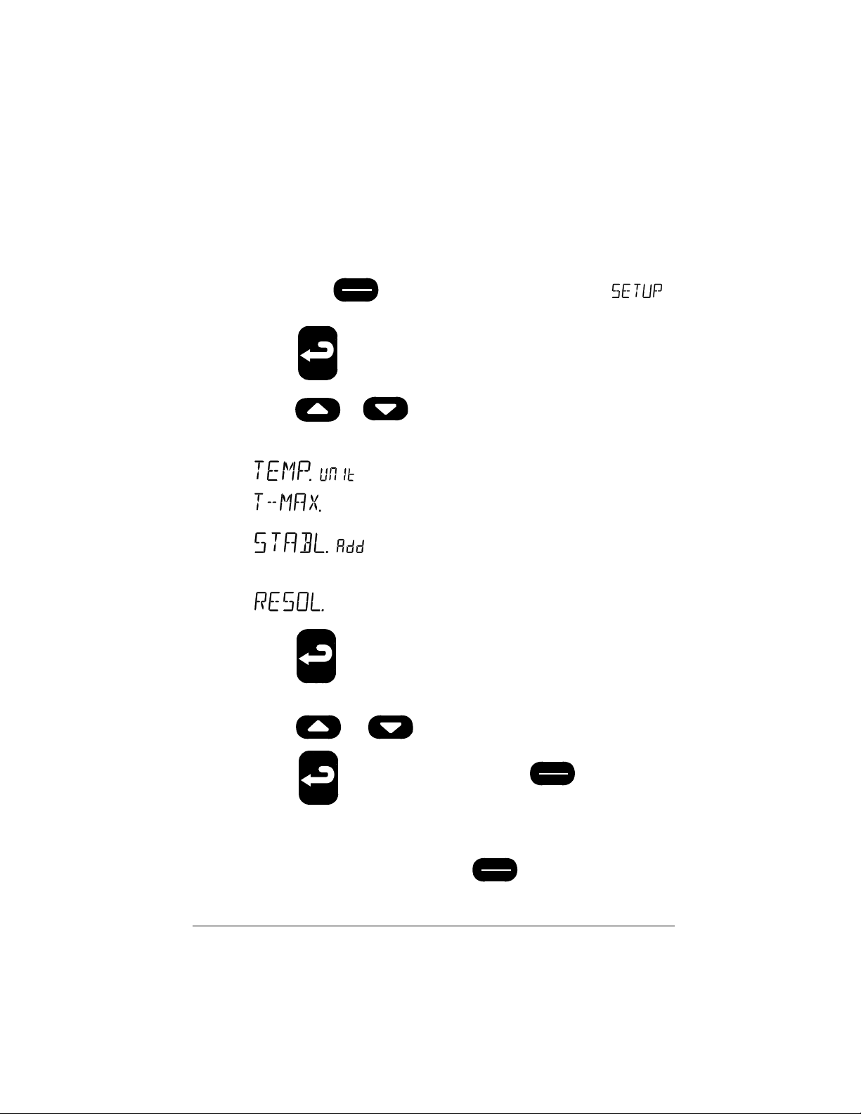
The MENU function (cf. Fig. 5) is used to modify the SETUP
parameters.
ESC
: The highest permissible temperature for
: Extra time which must elapse once the
well is stable before the check mark
symbol is displayed.
: Temperature resolution of 0 or 1
decimal.
Hold down
will appear on the display.
Press
Press or to toggle between the SETUP
parameters:
Press
MENU
for approx. 2 seconds. The word
. The first SETUP parameter will be displayed.
: Temperature unit °C or °F.
the calibrator.
to select the SETUP parameter you wish to
Press or to select the required value.
Press to accept your selection or
Once you have changed all SETUP parameters as required,
ESC
MENU
ESC
to cancel and
MENU
123943 08 13
Find Quality Products Online at: [email protected]
www.GlobalTestSupply.com
Page 26
4.0 After use
50°C/122°F.
ETC-125 A only.
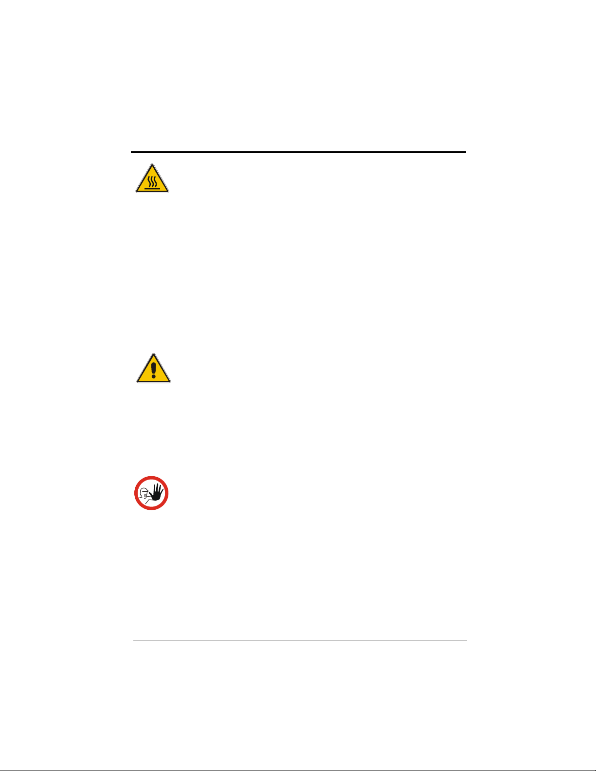
Caution – Hot surface
• Do not touch the well, the insertion tube or the grid
plate - they may be very hot and cause burns.
• Do not touch the tip of the sensor when it is removed
from the insertion tube/well – it may be very hot and
cause burns.
• Over 50°C/122°F
If the calibrator has been heated up to temperatures
above 50°C/122°F, you must wait until the instrument
reaches a temperature below 50°C/122°F before you
switch it off.
Warning……
• Never l
removed from the calibrator unsupervised – they may
constitute a fire hazard or personal injury.
eave hot insertion tubes which have been
• Do not remove the insertion tube from the calibrator
before the insertion tube has cooled down to less than
14 123943 08
Caution…
• The insertion tube must always be removed from the
calibrator after use.
The humidity in the air may cause corrosion oxidation
on the insertion tube inside the instrument. There is a
risk that the insertion tube may get stuck if this is
allowed to happen.
• If the calibrator is to be transported, the insertion tube
must be removed from the well to avoid damage to the
instrument.
Find Quality Products Online at: [email protected]
www.GlobalTestSupply.com
Page 27

• Scratches and other damage to the insertion tubes
should be avoided by storing the insertion tubes
carefully when not in use.
4.1 Switching off the calibrator
The following routine must be observed before the insertion tube is
removed and the instrument turned off (cf. Fig. 1) :
1. If the calibrator has been heated up to temperatures above
50°C/122°F, you must wait until the instrument reaches a
temperature below 50°C/122°F before you switch it off.
2. If the calibrator has reached a temperature below 0°C/32°F,
it should be heated momentarily to a temperature of
100°C/212°F.
3. Turn off the calibrator using the power control switch (pos.
4).
4. Remove the insertion tube from the calibrator using the tool
supplied with the instrument.
123943 08 15
Find Quality Products Online at: [email protected]
www.GlobalTestSupply.com
Page 28

Reference manual
Temperature Calibrator
JOFRA ETC-125 A / 400 A / 400 R
Copyright 2005 AMETEK Denmark A/S (123943-UK)
Find Quality Products Online at: [email protected]
www.GlobalTestSupply.com
Page 29

Page 30

List of contents
1.0 Introduction ............................................................................ 4
1.1 Warranty ....................................................................................... 5
2.0 Safety instructions ................................................................. 6
3.0 Setting up the calibrator ...................................................... 10
3.1 Receipt of the calibrator .............................................................. 10
3.2 Preparing the calibrator ............................................................... 12
3.3 Choice of insertion tube / correct bore in well. ........................... 14
3.4 Inserting the sensor .................................................................... 16
4.0 Operating the calibrator ....................................................... 18
4.1 Keyboard, display and connections ............................................ 18
4.2 Starting the calibrator .................................................................. 21
4.3 Selecting the set-temperature ..................................................... 21
4.4 Using the AUTO STEP ............................................................... 23
4.5 Using the MENU ......................................................................... 26
4.5.1 Adjusting the temperature unit ....................................... 27
4.5.2 Adjusting the max-temperature ...................................... 28
4.5.3 Adjusting the extra stability time ..................................... 28
4.5.4 Adjusting the temperature resolution ............................. 29
4.6 Calibrating IR-thermometers (ETC-400 R only) .......................... 30
4.7 Simulation/training ...................................................................... 33
0 Storing and transporting the calibrator .............................. 34
5.
6.0 Errors .................................................................................... 37
7.0 Returning the calibrator for service .................................... 39
8.0 Maintenance ......................................................................... 41
8.1 Cleaning ...................................................................................... 41
8.2 Adjusting and calibrating the instrument ..................................... 44
8.2.1 Adjusting the calibration date ......................................... 46
8.2.2 Calibrating/adjusting the instrument ............................... 47
8.2.3 Calibrating/adjusting the ETC-400 R .............................. 51
0 Technical specifications .............................
9.
10.0 List of accessories ............................................................... 58
......................... 52
123943 08 2019-04-12 3
Find Quality Products Online at: [email protected]
www.GlobalTestSupply.com
Page 31

1.0 Introduction
AMETEK Denmark A/S was ISO
Congratulations on your new AMETEK Jofra ETC
Calibrator!
With the AMETEK Jofra calibrator, you have chosen an extremely
effective instrument which we hope will live up to all your
expectations. Over the past many years, we have acquired extensive
knowledge of industrial temperature calibration. This expertise is
reflected in our products which are all designed for daily use in an
industrial environment. Please note that we would be very interested
in hearing from you if you have any ideas or suggestions for changes
to our products.
This reference manual applies to the following instruments:
• Jofra ETC-125 A
• Jofra ETC-400 A
• Jofra ETC-400 R
ISO-9001 certified
-9001 certified in September 1994
by Bureau Veritas Certification Denmark.
CE-label
*
ETC-125 A from serial no. xxxxxx-01328, ETC-400 A / ETC-400 R from serial no. xxxxxx-01798
4 2019-04-12 123943 08
Your new temperature calibrator bears the CE label
and conforms to the Electromagnetic Compatibility
(EMC) Directive 2014/30/EU and the Low Voltage
Directive 2014/35/EU and RoHS Recast (RoHS II)
Directive 2011/65/EU*.
Find Quality Products Online at: [email protected]
www.GlobalTestSupply.com
Page 32

Technical assistance
Please contact the dealer from whom you acquired the instrument if
you require technical assistance.
1.1 Warranty
This instrument is warranted against defects in workmanship,
material and design for two (2) years from date of delivery to the
extent that AMETEK will, at its sole option, repair or replace the
instrument or any part thereof which is defective, provided, however,
that this warranty shall not apply to instruments subjected to
tampering or, abuse, or exposed to highly corrosive conditions.
THIS WARRANTY IS IN LIEU OF ALL OTHER WARRANTIES
WHETHER EXPRESS OR IMPLIED AND AMETEK HEREBY
DISCLAIMS ALL OTHER WARRANTIES, INCLUDING, WITHOUT
LIMITATION, ANY WARRANTY OF FITNESS FOR A PARTICULAR
PURPOSE OR MERCHANTABILITY. AMETEK SHALL NOT BE
LIABLE FOR ANY INCIDENTAL OR CONSEQUENTIAL DAMAGES,
INCLUDING, BUT NOT LIMITED TO, ANY ANTICIPATED OR LOST
PROFITS.
This warranty is voidable if the purchaser fails to follow any and all
instructions, warnings or cautions in the instrument’s User Manual.
If a manufacturing defect is found, AMETEK will replace or repair the
instrument or replace any defective part thereof without charge;
however, AMETEK’s obligation hereunder does not include the cost
of transportation, which must be borne by the customer. AMETEK
assumes no responsibility for damage in transit, and any claims for
such damage should be presented to the carrier by the purchaser.
123943 08 2019-04-12 5
Find Quality Products Online at: [email protected]
www.GlobalTestSupply.com
Page 33

2.0 Safety instructions
Read this manual carefully before using
the instrument!
Please follow the instructions and procedures described in
this manual. They are designed to allow you to get the
most out of your calibrator and avoid any personal injuries
and/or damage to the instrument.
Disposal – WEEE Directive
Th
ese calibrators contain Electrical and Electronic circuits
and must be recycled or disposed of properly (in
accordance with the WEEE Directive 2002/96/EC).
Warning
About the use:
• The calibrator mu
other than those described in this manual, as it might
cause a hazard.
• The calibrator has been designed for indoor use only
and is not to be used in wet locations.
• The calibrator is not to be used in hazardous areas,
where vapour or gas leaks, etc. may constitute a
danger of explosion.
• The calibrator is a CLASS I product and must be
connected to a mains outlet with a protective earth
connection. Ensure the ground connection of the
calibrator is properly connected to the protective earth
before switching on the calibrator. Always use a mains
power cable with a mains plug that connects to the
protective earth.
• To ensure the connection to protective earth any
extension cord used must also have a protective earth
conductor.
st not be used for any purposes
6 2019-04-12 123943 08
Find Quality Products Online at: [email protected]
www.GlobalTestSupply.com
Page 34

• Only use a mains power cord with a current rating as
specified by the calibrator and which is approved for
the voltage and plug configuration in your area.
• Before switching on the calibrator make sure that it is
set to the voltage of the mains electricity supply.
• Always position the calibrator to enable easy and quick
disconnection of the power source (mains inlet socket).
• The calibrator must be kept free within an area of 20
cm on all sides and 1 metre above the calibrator due to
fire hazard.
• Never use heat transfer fluids such as silicone, oil,
paste, etc. in the calibrators. These fluids may
penetrate the calibrator and cause electrical hazard,
damage or create poisonous fumes.
• The calibrator must be switched off before any attempt
to service the instrument is made. There are no user
serviceable parts inside the calibrator.
• When cleaning the well or the insertion tube,
REMEMBER to wear goggles when using compressed
air in the dry-block calibrator.
• Avoid knocking, bumping or dropping the instrument.
This can cause permanent damage to the instrument
and loss of accuracy.
• Do not use this instrument for any application other
than calibration work.
• The calibration instruments should only be used by
TRAINED PERSONNEL.
About the insertion tubes and well:
• Never leave hot insertion tubes which have been
emoved from the calibrator unsupervised – they may
r
constitute a fire hazard or personal injury.
• If you intend to store the calibrator in the optional
aluminium carrying case after use, you must ensure
that the instrument has cooled down to a temperature
below 100°C/212°F before placing it in the carrying
case.
123943 08 2019-04-12 7
Find Quality Products Online at: [email protected]
www.GlobalTestSupply.com
Page 35

• Never place a hot insertion tube in the optional carrying
case.
Caution – Hot surface
This symbol is engraved in the well of the ETC-400 A and
in the grid plate of the ETC-125 A / 400 R.
• Do not touch the well, the insertion tube or the grid
plate, as the calibrator is heating up / has been heated
up – they may be very hot and cause burns.
• Do not touch the tip of the sensor when it is removed
from the insertion tube/well – it may be very hot and
cause burns.
• Over 50°C/122°F
If the calibrator has been heated up to temperatures
above 50°C/122°F, you must wait until the instrument
reaches a temperature below 50°C/122°F before you
switch it off.
• Do not remove the insert from the calibrator before the
insert has cooled down to less than 50°C/122°F.
Caution – Cold surface
Below 0°C/32°F (applies only to the ETC-125 A models)
Do not touch the well or insertion tube when these are
•
below 0°C/32°F - they might create frostbite.
• If the calibrator has reached a temperature below
0°C/32°F, ice crystals may form on the insertion tube
and the well. This, in turn, may cause the material
surfaces to oxidize
To prevent this from happening, simply heat up the
calibrator to 100°C/212°F until all water left has
evaporated.
It is very important that humidity in the well and insertion
tube is removed to prevent corrosion and frost
expansion damages.
8 2019-04-12 123943 08
Find Quality Products Online at: [email protected]
www.GlobalTestSupply.com
Page 36

Caution…
About the use:
• Do not use the instrument if the fan is out of order.
• Before cleaning the calibrator, you must switch it off,
allow it to cool down and remove all cables.
About the well, insertion tube and grid plate:
• The well and the insertion tube must be clean before
use.
• Do not pour any form of liquids into the well. It might
damage the well or cause a hazard.
• Scratches and other damage to the insertion tubes
should be avoided by storing the insertion tubes
carefully when not in use.
• The insertion tube must never be forced into the well.
The well could be damaged as a result, and the
insertion tube may get stuck.
• The insertion tube must always be removed from the
calibrator after use.
The humidity in the air may cause corrosion oxidation
on the insertion tube inside the instrument. There is a
risk that the insertion tube may get stuck if this is
allowed to happen.
123943 08 2019-04-12 9
Note…
The product liability onl
to a manufacturing defect. This liability becomes void if the
user fails to follow the maintenance instructions set out in
this manual or uses unauthorised spare parts.
y applies if the instrument is subject
Find Quality Products Online at: [email protected]
www.GlobalTestSupply.com
Page 37
3.0 Setting up the calibrator
3.1 Receipt of the calibrator
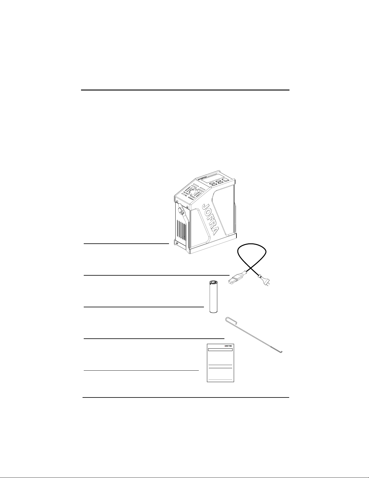
When you receive the instrument…
• Carefully unpack and check the calibrator and the accessories.
• Check the parts off against the list shown below.
If any of the parts are missing or damaged, please contact the
dealer who sold the calibrator.
You should receive:
• 1 calibrator
• 1 mains power cable
• 1 insertion tube (ETC-125 A only)
• 1 tool for insertion tube (ETC-125 A only)
• 1 traceable calibration certificate
Calibration Certificate
Calibration Equipment
xxxxxxxxxxxx
Calibration Traceability
xxxxxxxxxxxx
xxxxxxxxxxxx
Calibration Conditions
xxxxxxxxxxxx
xxxxxxxxxxxx
xxxxxxxxxxxx
Calibration Results
xxxx xxxx
xxxxxx
xxxxxx
xxxxxx
xxxxxx
xxxxxx
xxxxxx
xxxxxx
xxxxxx
Calibration Procedure
xxxxxxxxxxxx
xxxxxxxxxxxx
xxxx xxxx xxxx xxxx
xxxxxx
xxxxxx
xxxxxx
xxxxxx
xxxxxx
xxxxxx
xxxxxx
xxxxxx
CALIBRATION INSTRUMENTS
xxxxxx
xxxxxx
xxxxxx
xxxxxx
xxxxxx
xxxxxx
xxxxxx
xxxxxx
10 2019-04-12 123943 08
Find Quality Products Online at: [email protected]
www.GlobalTestSupply.com
Page 38
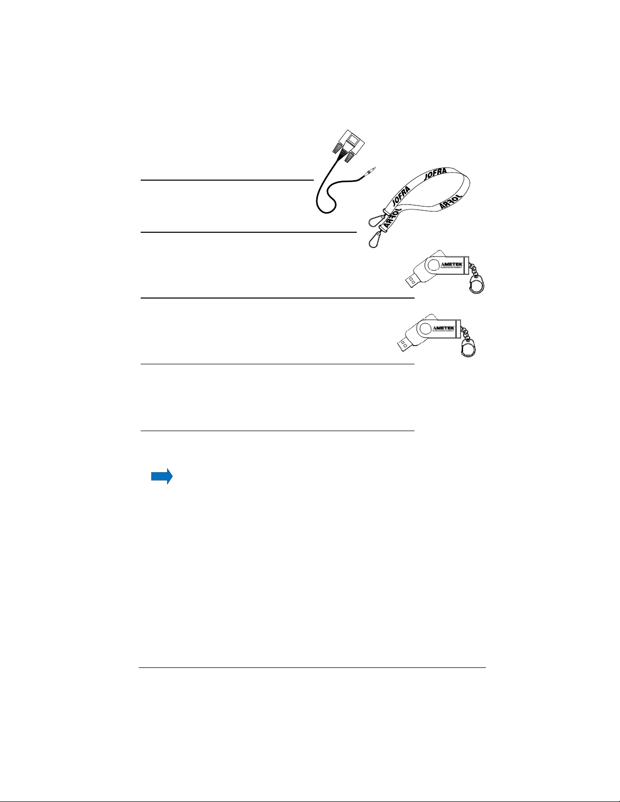
• 1 RS 232 serial cable
• 1 shoulder strap
• 1 USB-key containing User-/Reference manual
and software package “JOFRACAL”
• 1 USB-key containing JOFRA IR-LAB
calibration software (ETC-400 R only)
• 1 correction table for emissivity
(ETC-400 R only)
When reordering, please specify the parts number found
in the list of accessories, section 10.0.
123943 08 2019-04-12 11
Find Quality Products Online at: [email protected]
www.GlobalTestSupply.com
Page 39

3.2 Preparing the calibrator
Warning
• The calibrator has been designed for indoor use only
and is not to be used in wet locations.
• The calibrator is not to be used in hazardous areas,
where vapour or gas leaks, etc. may constitute a
danger of explosion.
• The calibrator is not designed for operation in altitudes
above 2000 meters.
• The calibrator is a CLASS I product and must be
connected to a mains outlet with a protective earth
connection. Ensure the ground connection of the
calibrator is properly connected to the protective earth
before switching on the calibrator. Always use a mains
power cable with a mains plug that connects to the
protective earth.
• To ensure the connection to protective earth any
extension cord used must also have a protective earth
conductor.
• Only use a mains power cord with a current rating as
specified by the calibrator and which is approved for the
voltage and plug configuration in your area.
• Before switching on the calibrator make sure that it is
set to the voltage of the mains electricity supply.
• Always position the calibrator to enable easy and quick
disconnection of the power source (mains inlet socket).
• The calibrator must be kept clear within an area of 20
cm on all sides and 1 metre above the calibrator due to
fire hazard.
• Never use heat transfer fluids such as silicone, oil,
paste, etc. in the calibrators. These fluids may
penetrate the calibrator and cause electrical hazard,
damage or create poisonous fumes.
12 2019-04-12 123943 08
Find Quality Products Online at: [email protected]
www.GlobalTestSupply.com
Page 40
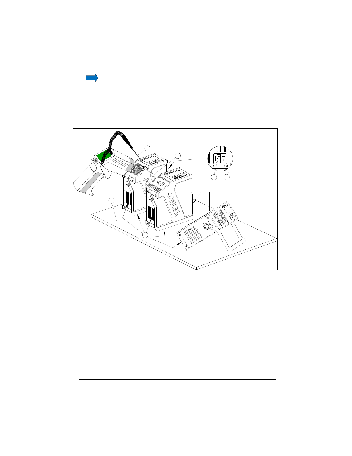
Note…
The instrument must not be exposed to draughts.
Especially the temperature of the target unit surface on the
ETC-400 R might be affected by this.
6
5
1
2
115 V
3
4
Fig. 1
123943 08 2019-04-12 13
Find Quality Products Online at: [email protected]
www.GlobalTestSupply.com
Page 41

When setting up the calibrator, you must…(see fig. 1)
diameter and
125 A only)
or use one of the bores in the well that best suits your needs.
See section 3.3 for information on how to select the insertion
Place the calibrator on an even horizontal surface in the spot
you intend to use it.
Caution…
The calibrator is now ready for use.
Section 3.3 and 3.4 are for ETC-125 / 400 A only
Do not use the instrument if the fan is out of order.
Ensure a free supply of air to the fan.
Check that the voltage shown on the label above the power
control switch is identical to the mains voltage (ETC-400 A/R
only). If not, the instrument should be returned to AMETEK
Denmark A/S or the distributor for replacement.
Check that the earth connection for the instrument is present
d attach the cable.
an
Select an insertion tube with the correct bore
place it in the largest bore of the instrument (ETC-
tube/ correct bore in the well.
3.3 Choice of insertion tube / correct bore in
well.
Caution…
To get the best results out of your calibrator, the insertion
14 2019-04-12 123943 08
Find Quality Products Online at: [email protected]
tube dimensions, tolerance and material are critical. We
highly advise using the JOFRA insertion tubes, as they
guarantee trouble free operation. Use of other insertion
tubes may reduce performance of the calibrator and cause
the insertion tube to get stuck.
www.GlobalTestSupply.com
Page 42

Caution…
Before using new insertion tubes for calibration in the ETC-
Insertion tubes are only available for the ETC-125 A.
An insertion tube is selected on the basis of the diameter of the
sensor to be calibrated. You may choose between an 8 mm / 5/16
inch insertion tube, an 3/8 inch insertion tube or alternatively, you
may order an undrilled insertion tube and drill the required hole
yourself. The finished dimension should be as follows:
• Sensor diameter +0.2 +0.05/-0 mm.
bore is selected on the basis of the diameter of the sensor to be
A
calibrated. The sensor can now be inserted directly into the bore of
the well. See Fig. 2 for various design combinations.
125 instrument, the insertion tubes must be heated up to
maximum temperature 125°C (257°F) for a period of
minimum 30 minutes.
123943 08 2019-04-12 15
Find Quality Products Online at: [email protected]
www.GlobalTestSupply.com
Page 43
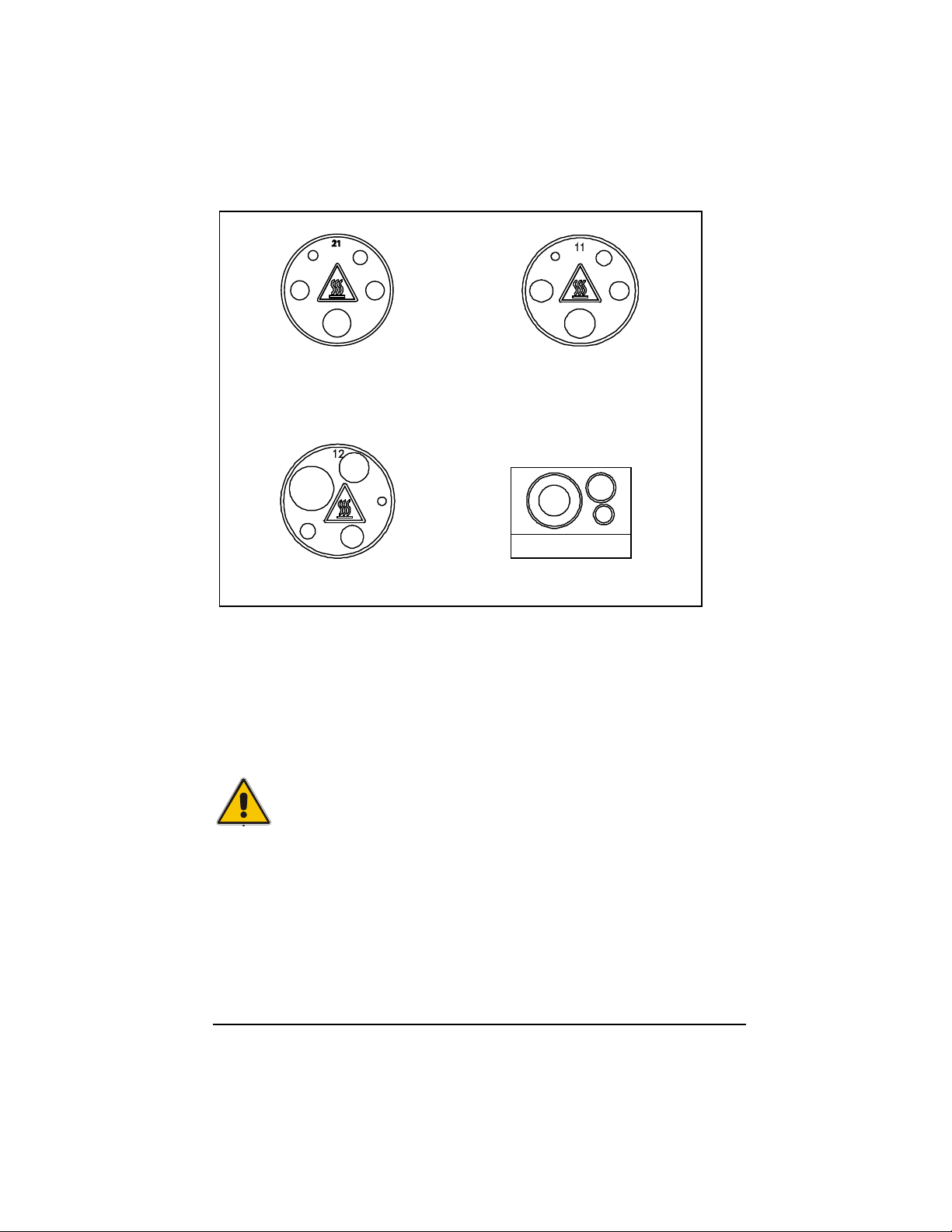
The various design combinations to choose from.
6 mm
3mm
4mm
3/16 in.
2mm
4mm
Metric - ETC-400 A
1/4 in.
3/8 in.
1/8 in.
3/16 in.
1/16 in.
12.5mm
1/2 in.
Imperial - ETC-400 A
Fig. 2
3.4 Inserting the sensor
1/16 in.
1/8 in.
5/32 in.
1/4 in.
Imperial - ETC-400 A
8mm
5/16 in.
6mm
1/4 in.
4mm
5/32 in.
ETC-125 A
Before inserting the sensor and switching on the calibrator, please
te the following important warning:
no
Warning
Never use heat transfer fluids such as silicone, oil, paste,
etc. These fluids may penetrate the calibrator and cause
electrical hazard, damage or create poisonous fumes.
Insert the sensor as shown in Fig. 1, pos. 6.
16 2019-04-12 123943 08
Find Quality Products Online at: [email protected]
www.GlobalTestSupply.com
Page 44

Caution…
• The well and the insertion tube must be clean before
use.
• Scratches and other damage to the insertion tube
should be avoided by storing the insertion tube carefully
when not in use.
• The insertion tube must never be forced into the well.
The well could be damaged as a result, and the
insertion tube may get stuck.
Caution – Hot surface
• Do not touch
tube while the calibrator is heating up – they may be
very hot and cause burns.
• Do not touch the tip of the sensor when it is removed
from the insertion tube – it may be very hot and cause
burns.
• Do not remove the insert from the calibrator before the
insert has cooled down to less than 50°C/122°F.
Caution – Cold surface
Below 0°C/32°F (applies only to the ETC-125 A models)
• Do not touch the well or insertion tube when these are
below 0°C/32°F - they might create frostbite.
• If the calibrator has reached a temperature below
0°C/32°F, ice crystals may form on the insertion tube
and the well. This, in turn, may cause the material
surfaces to oxidize
To prevent this from happening, simply heat up the
calibrator to 100°C/212°F until all water left has
evaporated.
the grid plate, the well or the insertion
123943 08 2019-04-12 17
Find Quality Products Online at: [email protected]
www.GlobalTestSupply.com
Page 45
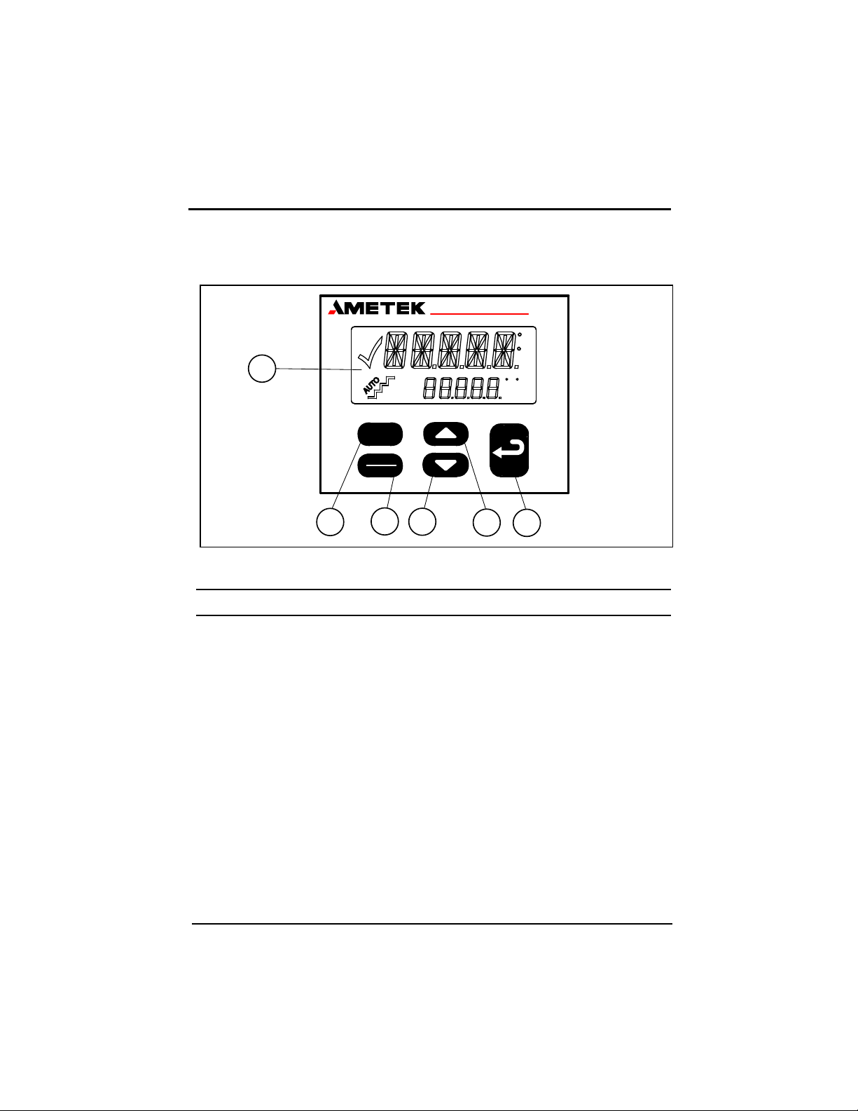
4.0 Operating the calibrator
4.1 Keyboard, display and connections
Keyboard
C
min
ETC
C
F
F
6
Fig. 3
Pos. Description
1
CALIBRATION INSTRUMENTS
AUTO
STEP
ESC
MENU
2
3
4
5
18 2019-04-12 123943 08
LCD.
AUTO STEP button used to activate AUTO STEP.
The function is used to switch between a series of settemperatures automatically.
ESC/MENU button used as Escape key or to activate the
menu system (hold button down for min. 2 seconds).
DOWN ARROW button used to adjust temperature values
(value decreases) and to select menu options.
UP ARROW button used to adjust temperature values
alue increases) and to select menu options.
(v
ENTER button used to accept chosen options.
Find Quality Products Online at: [email protected]
www.GlobalTestSupply.com
Page 46
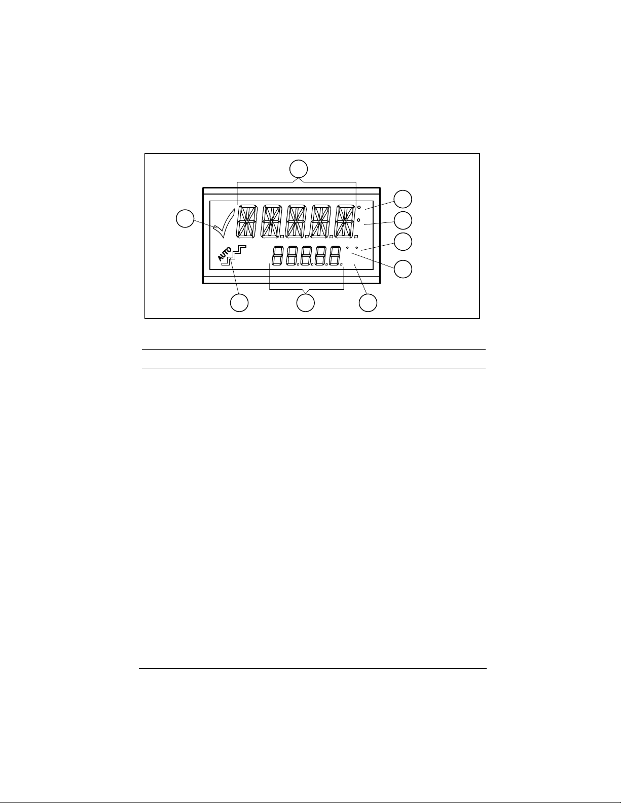
Display
Fig. 4
Pos. Description
1
9
8
C
F
F
C
min
2
3
4
7
6
5
123943 08 2019-04-12 19
CHECKMARK displayed when the calibrator is stable.
AUTO STEP symbol used to indicate that the function is
active (symbol flashes repeatedly).
Used to display set-temperatures, time-until-stable and
parameter values in the menu system.
Minute time unit for bottom display.
Celsius temperature unit for bottom display.
Fahrenheit temperature unit for bottom display.
Fahrenheit temperature unit for top display.
Celsius temperature unit for top display.
Used to display Read-temperature and parameters in the
nu system.
me
Find Quality Products Online at: [email protected]
www.GlobalTestSupply.com
Page 47
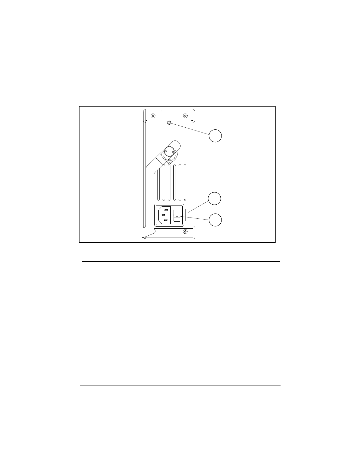
Connections
All connections are located on the back of the instrument.
2
3
115 V
1
Fig. 5
Pos. Description
Power control switch with connection for cable and on/off
switch.
Connection for RS232 cable.
Voltage label.
It is very important that the voltage shown on the label is
identical to the mains voltage.
20 2019-04-12 123943 08
Find Quality Products Online at: [email protected]
www.GlobalTestSupply.com
Page 48
°C
4.2 Starting the calibrator
Switch the calibrator on using the power control switch (Fig.
5, pos. 1).
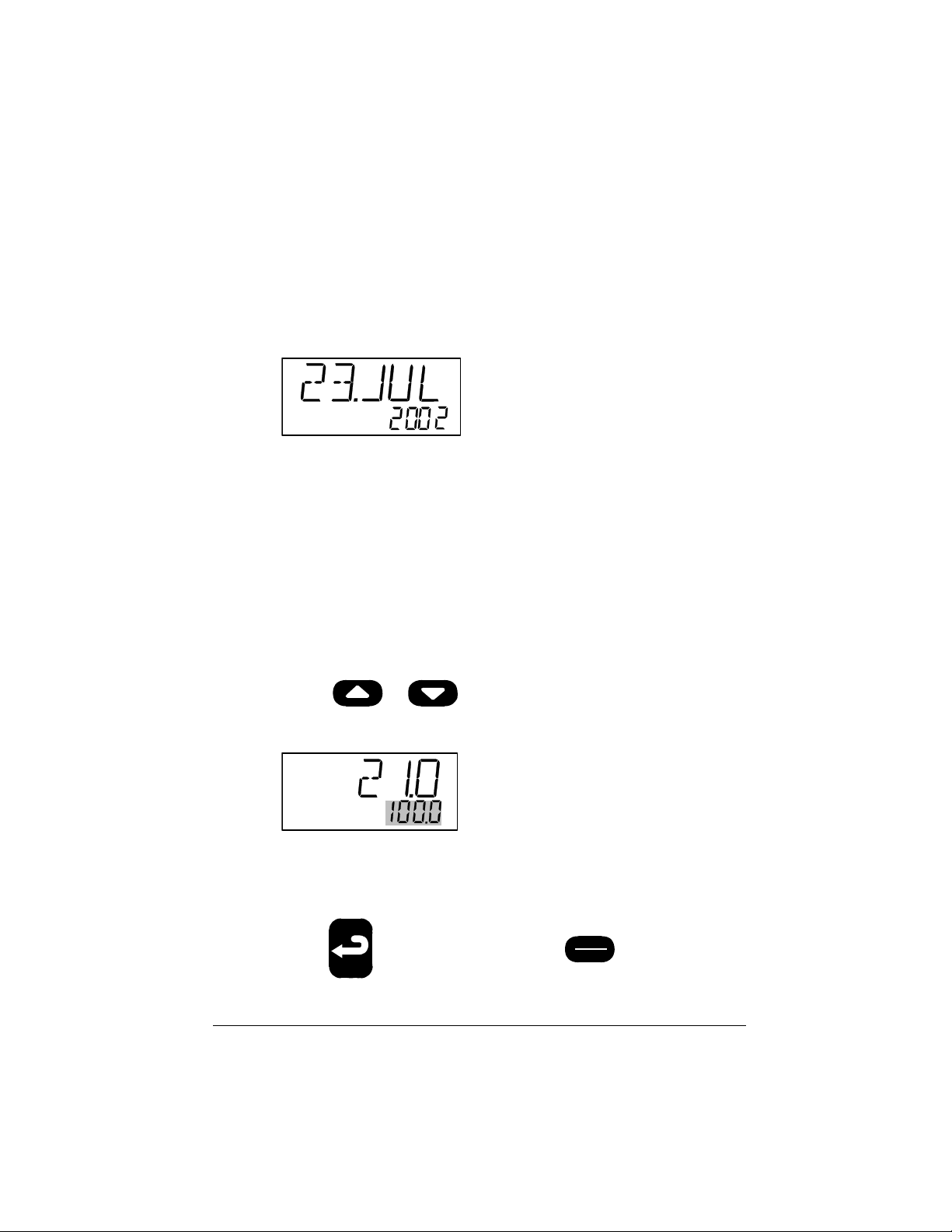
The instrument is initialised and the last calibration date is
displayed:
The calibration date will be displayed for approx. 2 seconds.
The initialisation process has been completed and the
calibrator is ready for use.
All settings are stored when the calibrator is switched off.
When the instrument is switched back on again, the status
will be the same as when it was switched off.
4.3 Selecting the set-temperature
ess or
Pr
to adjust the set-temperature.
The current selection flashes in the bottom display:
°C
The starting point is the last chosen set-temperature (even if
the instrument has been switched off).
Pr
ess
to accept the change or
ESC
MENU
to cancel.
The calibrator will now heat up/cool down.
123943 08 2019-04-12 21
Find Quality Products Online at: [email protected]
www.GlobalTestSupply.com
Page 49
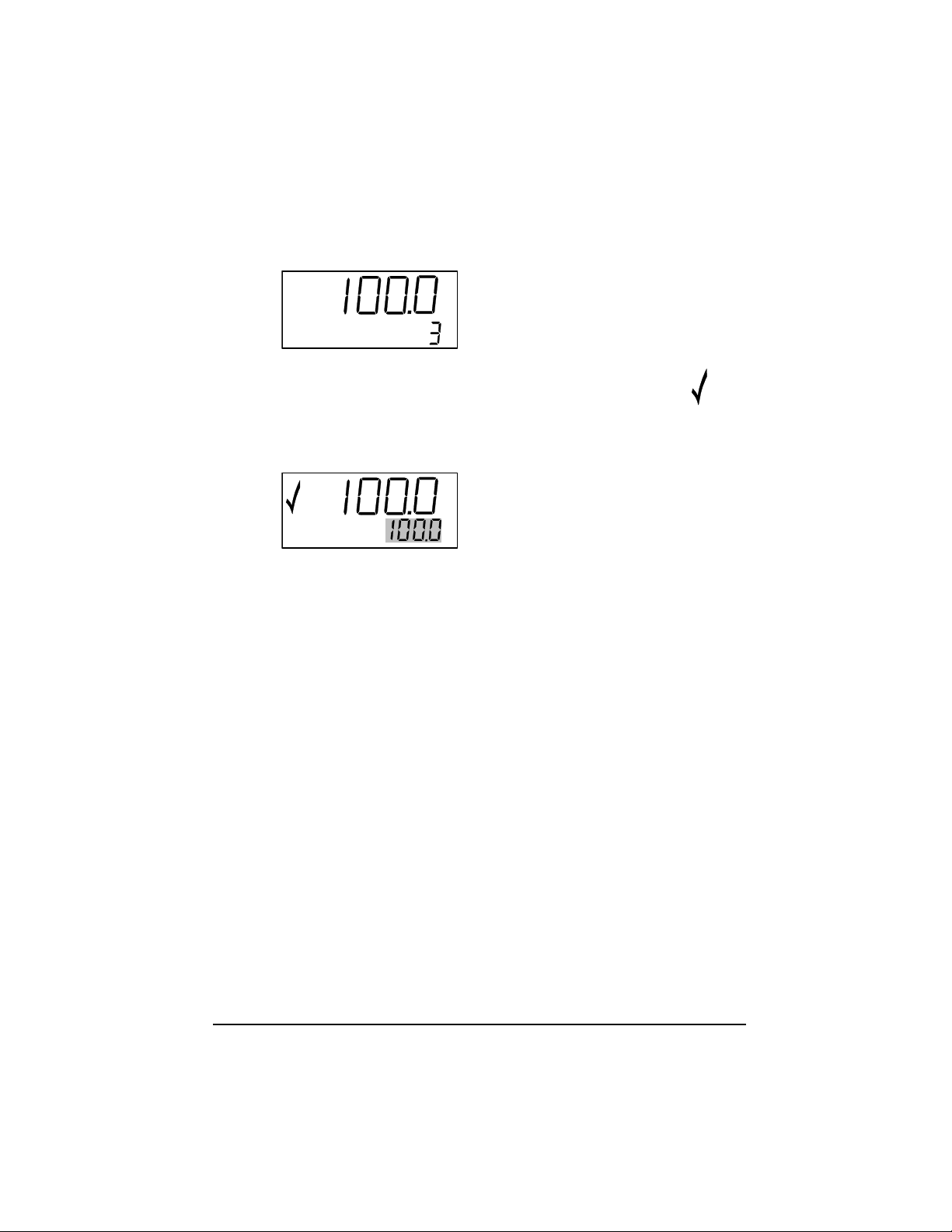
The top display continuously shows the read-temperature.
°C
°C
The bottom display shows either the set-temperature or the
estimated time in whole minutes until the calibrator will be
stable:
min
When the calibrator is stable the display will show the
checkmark symbol. The instrument will emit an audible
alarm and the estimated time until stable will be replaced by
the set-temperature:
°C
22 2019-04-12 123943 08
Find Quality Products Online at: [email protected]
www.GlobalTestSupply.com
Page 50
4.4 Using the AUTO STEP
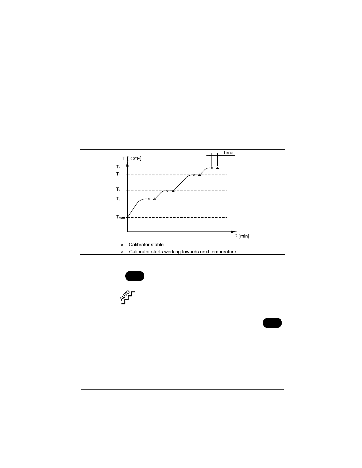
AUTO STEP is used to step automatically between a range of
different calibration temperatures. This is useful when calibrating
sensors in places which are hard to reach, and when calibrating
sensors for which the output is displayed in a different location.
The function can be illustrated using the following example:
Fig. 6
The symbol for AUTO STEP flashes to indicate that
Press .
the function is active.
The function can be cancelled at any time by pressing
AUTO
STEP
ESC
MENU
123943 08 2019-04-12 23
Find Quality Products Online at: [email protected]
www.GlobalTestSupply.com
Page 51
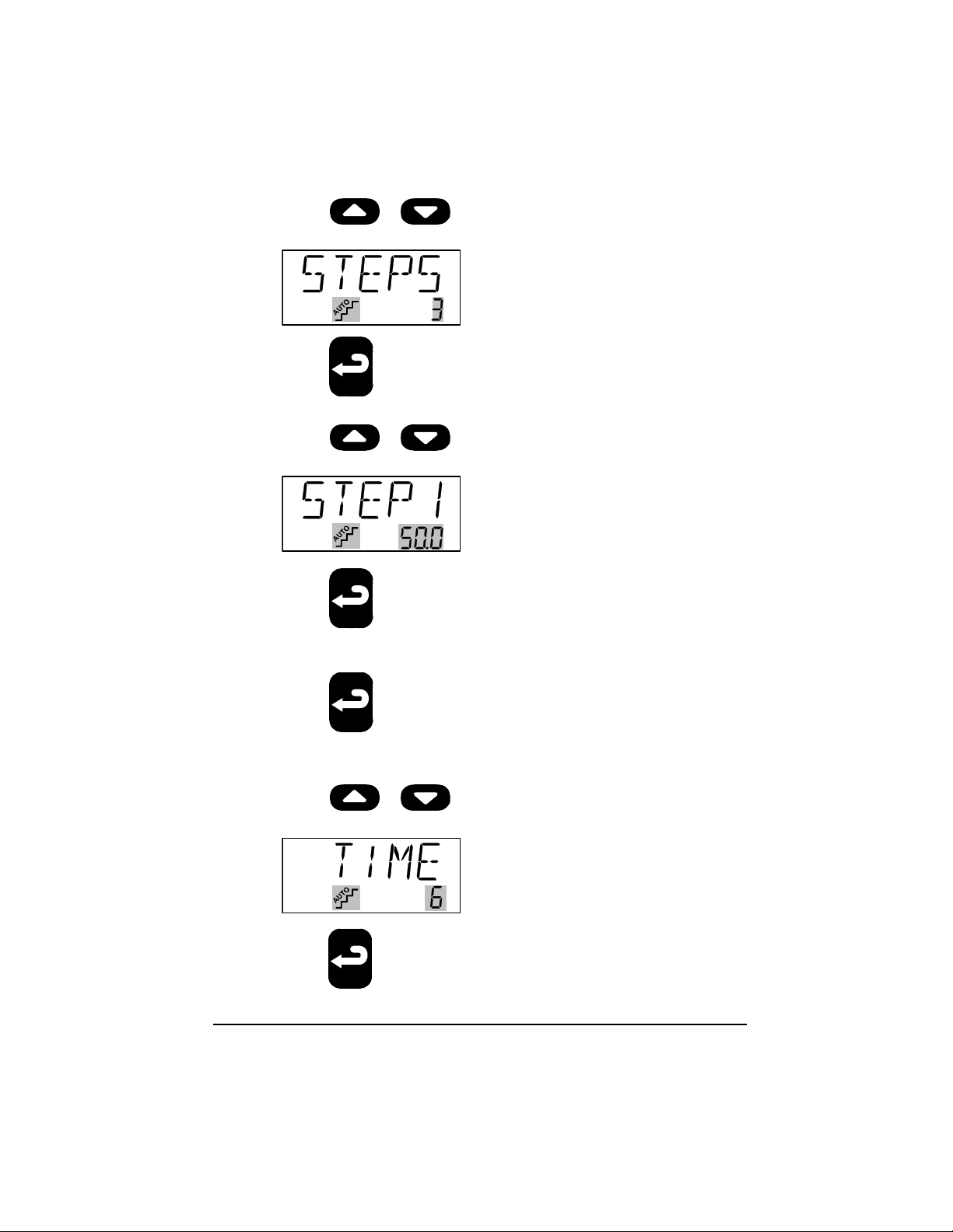
min
Press or to select the required number of
steps (minimum 2 steps, maximum 8 steps):
Press
to accept your selection.
Repeat the above procedure for all temperature steps.
Press or to select the required set-temperature
for step 1:
°C
Press to accept your selection.
Press
the last temperature step.
Press or to set the amount of extra time you
wish the calibrator to remain at every step:
to accept your choices once you have adjusted
Pr
24 2019-04-12 123943 08
Find Quality Products Online at: [email protected]
ess
www.GlobalTestSupply.com
to accept your selection.
Page 52
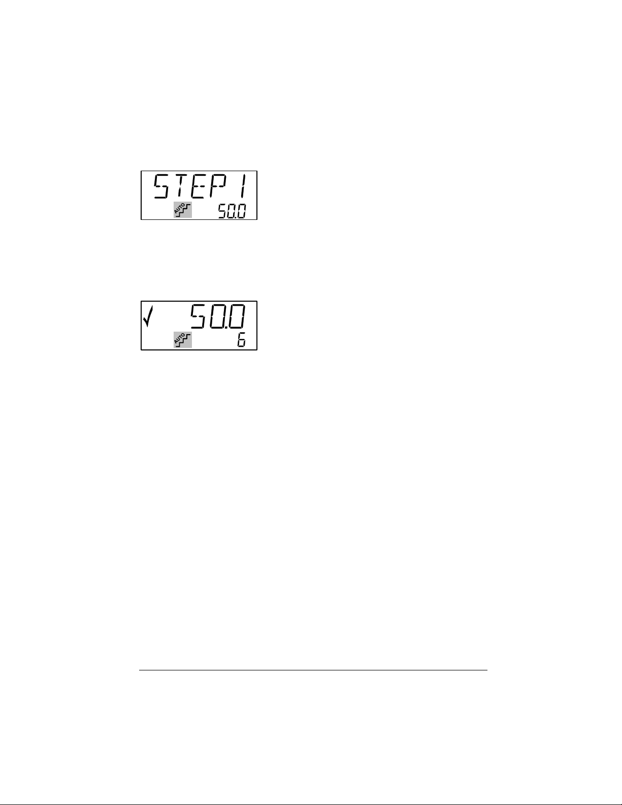
°C
The following will be displayed for one second to indicate that the
calibrator is ready to work towards the set-temperature:
°C
The calibrator will now work towards the given set-temperature. An
audible alarm will be emitted once the calibrator is stable.
The calibrator will wait the specified amount of extra time. The
instrument indicates this by counting down the amount of time
remaining:
min
The calibrator will then go to the next step. The procedure is the
same as for the first step. This process will be repeated until the last
step has been executed and the function has been completed.
123943 08 2019-04-12 25
Find Quality Products Online at: [email protected]
www.GlobalTestSupply.com
Page 53
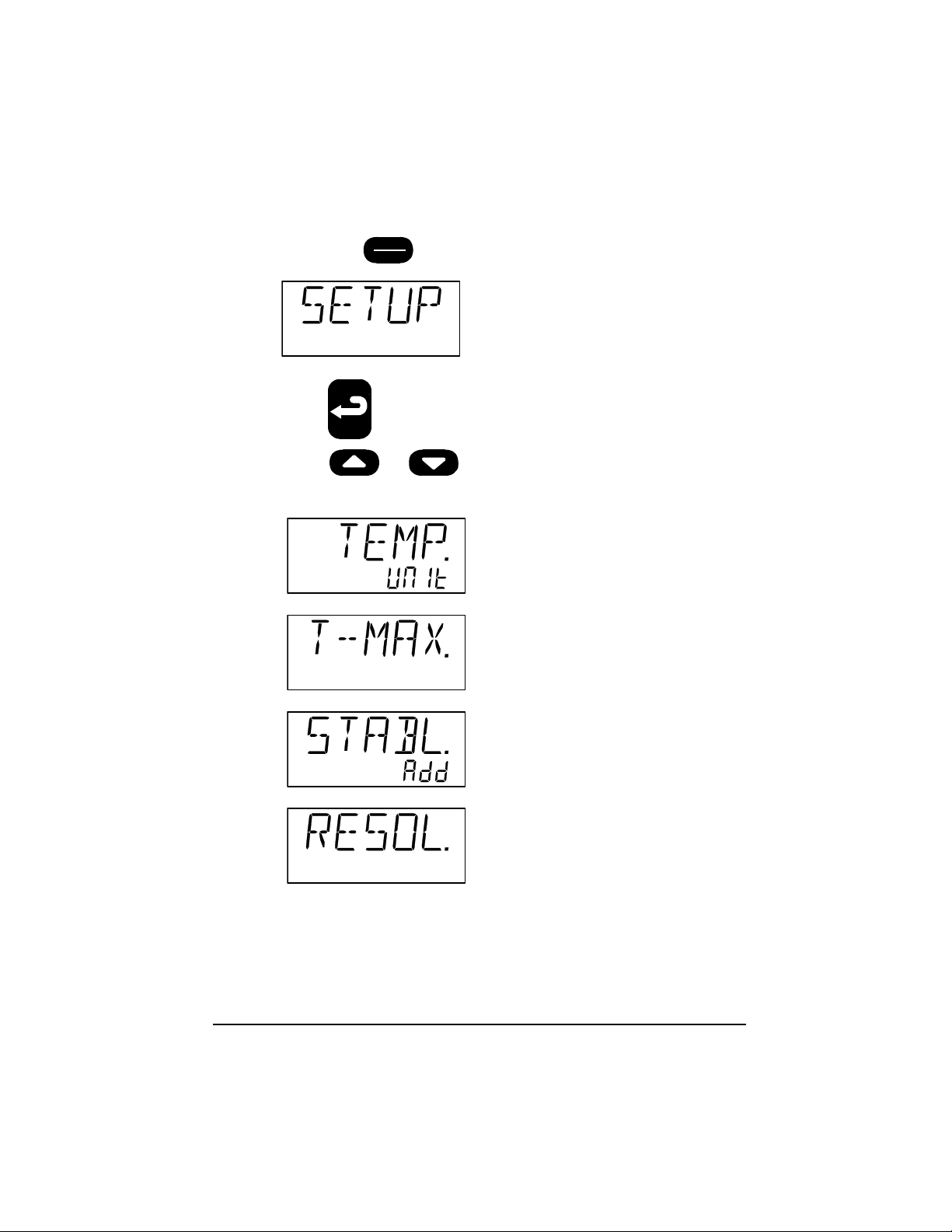
4.5 Using the MENU
ESC
Hold down
MENU
for more than approx. 2 seconds:
Press
Press or to switch between the adjustable
parameters:
to select SETUP.
26 2019-04-12 123943 08
Find Quality Products Online at: [email protected]
www.GlobalTestSupply.com
Page 54
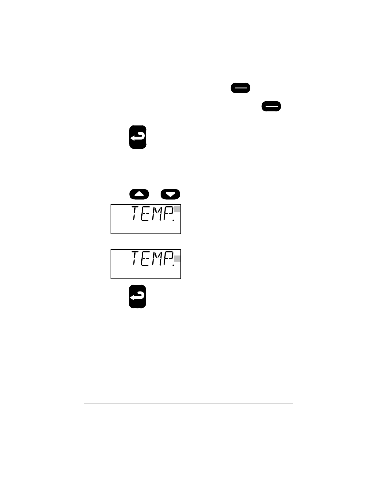
°C
°F
ESC
If you wish to exit SETUP, simply press .
The instrument will ignore all changes if you press
when adjusting any of the parameters.
MENU
ESC
MENU
Press to adjust the parameter.
4.5.1 Adjusting the temperature unit
ess or to switch between °C and °F:
- and
Pr
Press
to accept your selection.
123943 08 2019-04-12 27
Find Quality Products Online at: [email protected]
www.GlobalTestSupply.com
Page 55
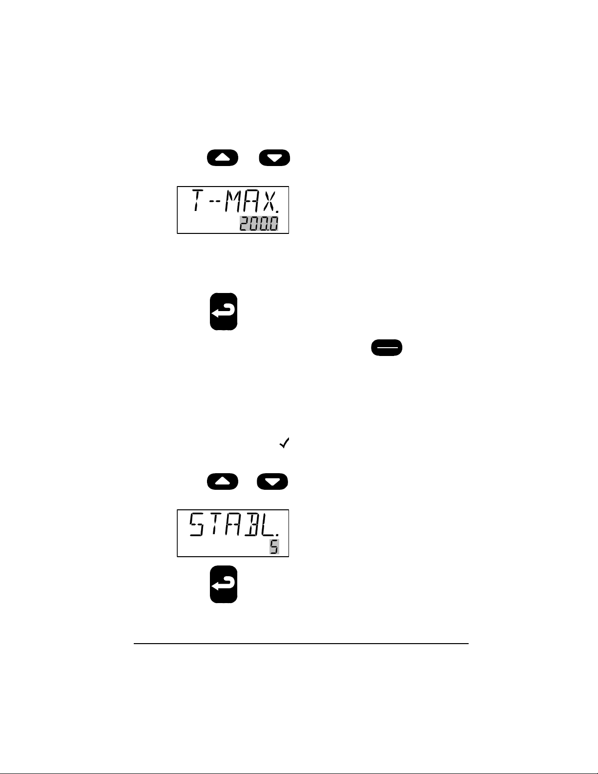
4.5.2 Adjusting the max-temperature
min
If the current set-temperature is higher than the new max-
Press or to set the max-temperature in steps
of 0.1°C or 0.1°F:
°C
temperature, you will need to adjust the set-temperature.
The instrument will immediately begin to cool (if required) as
soon as the new max-temperature is accepted.
ess
Pr
If you wish to exit SETUP, simply press
to accept your selection.
ESC
MENU
.
4.5.3 Adjusting the extra stability time
The extra stability time is the amount of extra time you wish to elapse
before the checkmark symbol is displayed after the calibrator has
stabilised.
Press or
0 and 20 minutes:
Pr
ess
to accept your selection.
to set the time to anywhere between
28 2019-04-12 123943 08
Find Quality Products Online at: [email protected]
www.GlobalTestSupply.com
Page 56
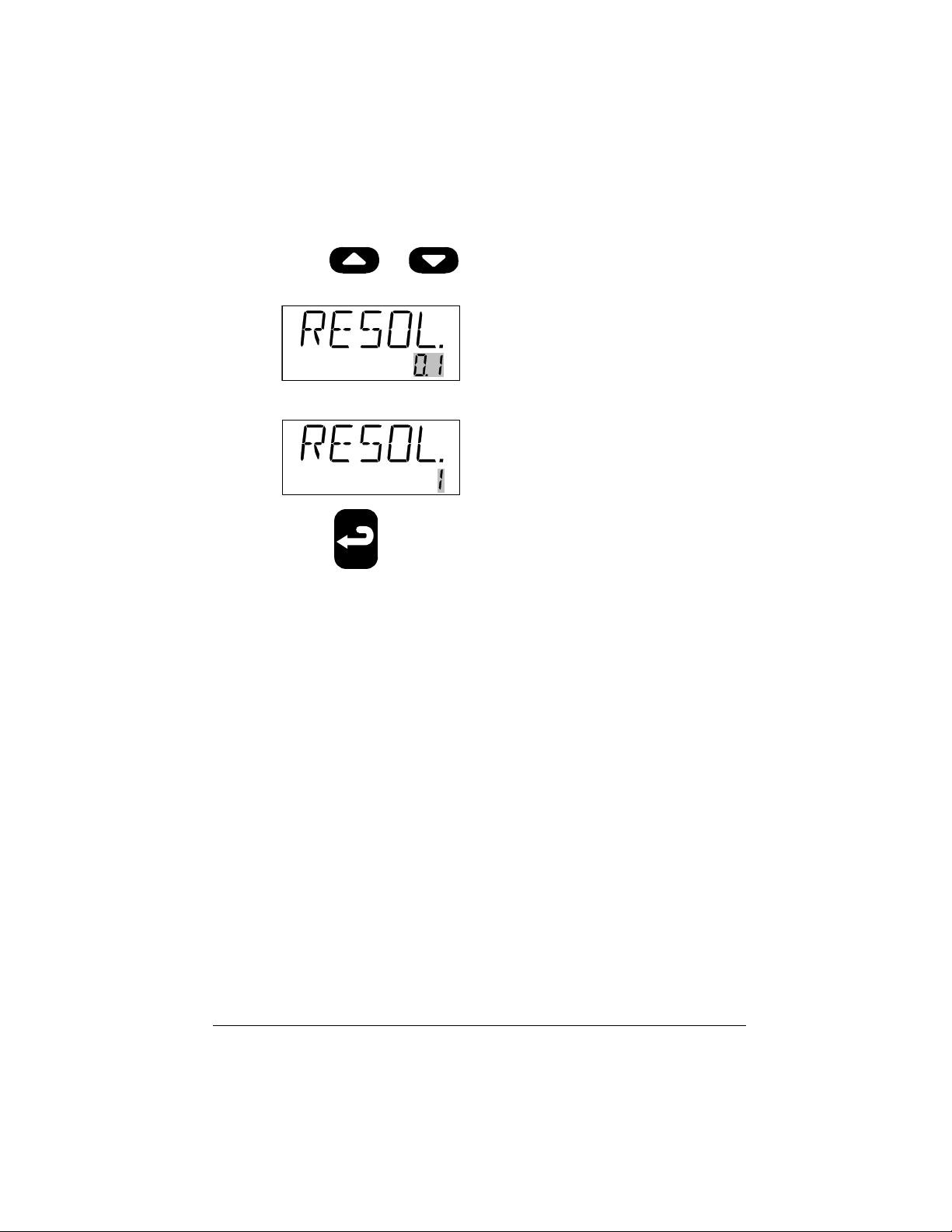
4.5.4 Adjusting the temperature resolution
- and
Press
decimals:
ess
Pr
or to select the required number of
°C
°C
to accept your selection.
123943 08 2019-04-12 29
Find Quality Products Online at: [email protected]
www.GlobalTestSupply.com
Page 57
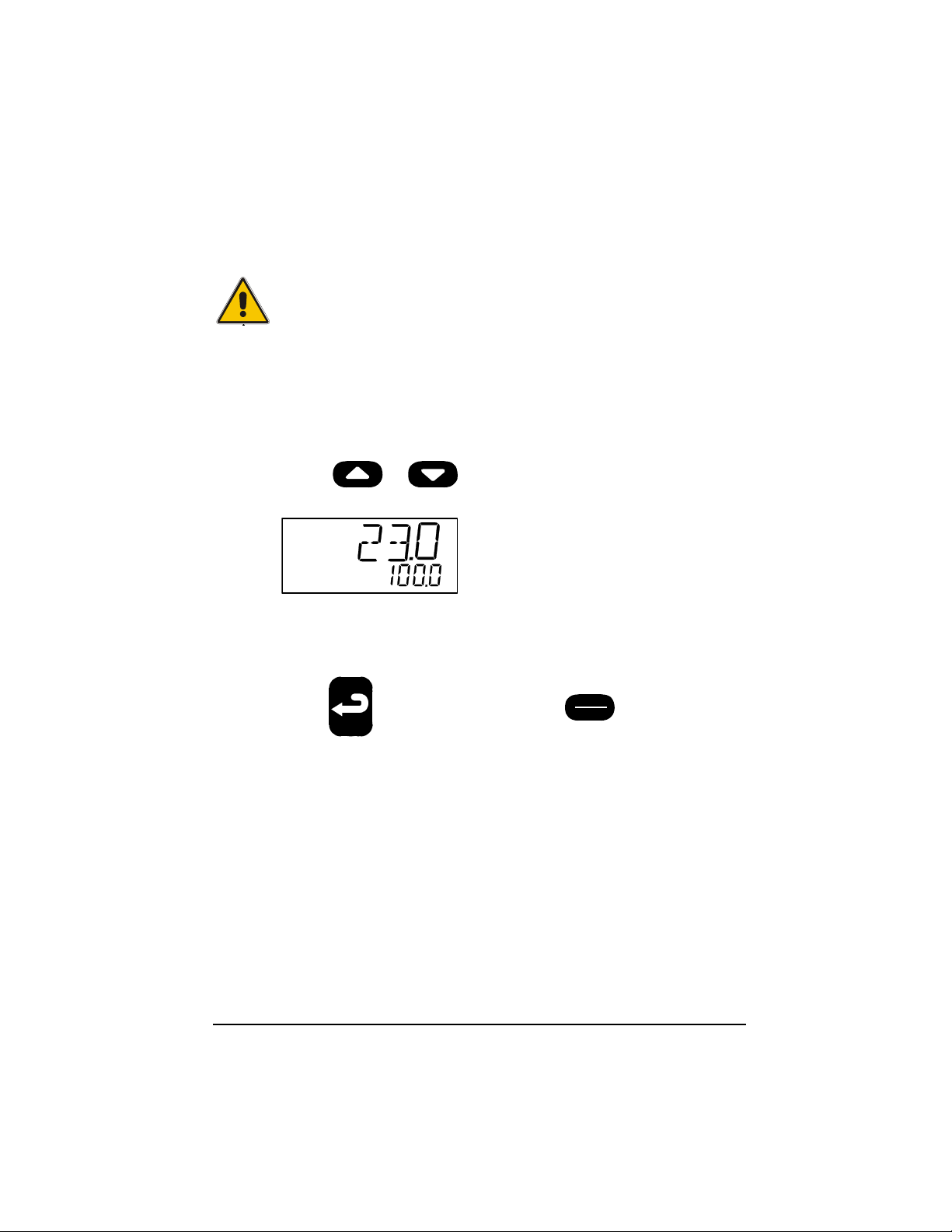
4.6 Calibrating IR-thermometers (ETC-400 R
°C
only)
Warning
• Do never allow any foreign material to come in
contact with the target unit surface, as the emission
factor of the target unit might change.
• Do not touch the target unit surface and the grid
plate – they may be very hot and cause burns.
Press or
temperature.
The starting point is the last chosen test-temperature (even
if the instrument has been switched off).
Press
to accept the change or
to select the required test-
°C
ESC
to cancel.
MENU
The calibrator will now heat up/cool down.
The top display continuously shows the read-temperature.
The bottom display shows that the calibrator is working
towards the given test-temperature.
30 2019-04-12 123943 08
Find Quality Products Online at: [email protected]
www.GlobalTestSupply.com
Page 58
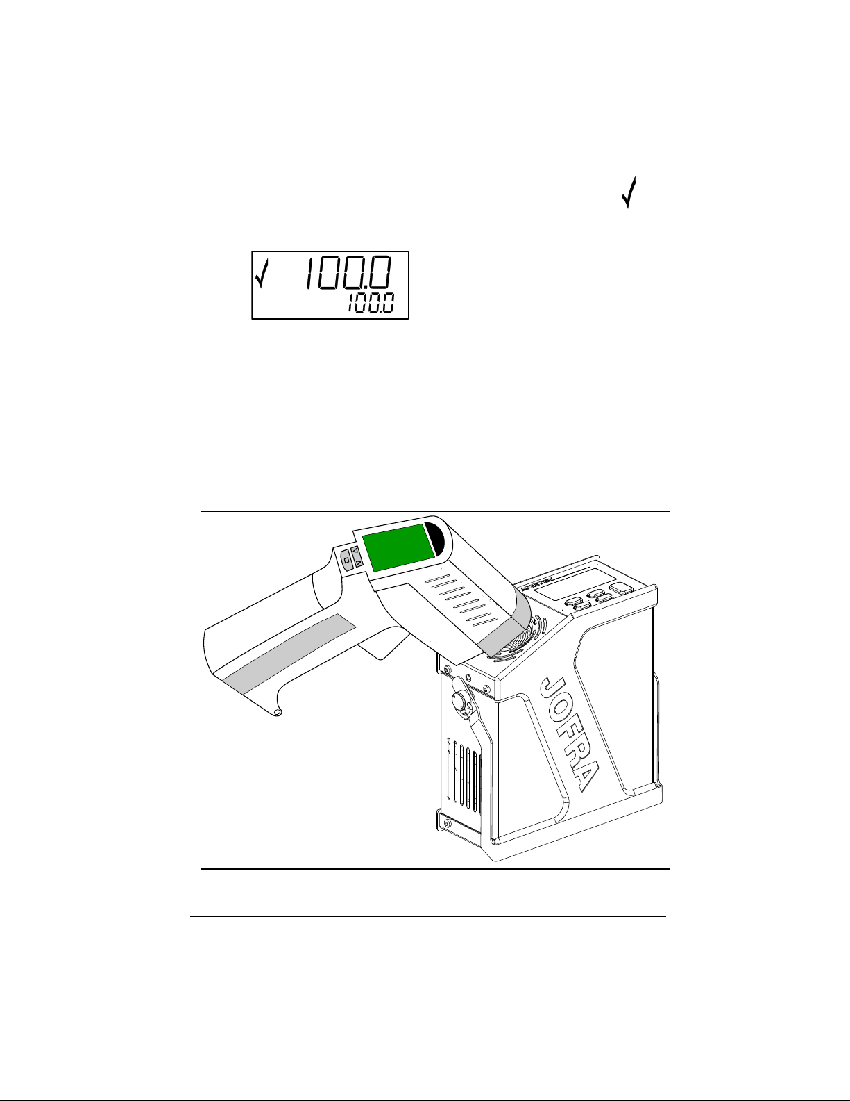
°C
When the calibrator is stable, the display will show the
checkmark symbol. The instrument will emit an audible
alarm and the calibrator is now ready for use.
°C
Select the emission factor of the target unit on the IR
thermometer to be calibrated. If your IR-thermometer has a
fixed emissivity setting, use the IRLAB software to calculate
corrections.
Point the IR thermometer perpendicular towards the target
unit surface.
It is very important that the thermometer is held close to the
target unit surface.
Fig. 7
123943 08 2019-04-12 31
Find Quality Products Online at: [email protected]
www.GlobalTestSupply.com
Page 59

Ensure the thermometer’s “field of vision” is centred and contained
within the surface area of the target unit. See fig. 7.
If the calibration is not carried out as described, the result of the
calibration will not be accurate.
Caution…
Avoid contact to the target unit surface with the
thermometer during operation, as the thermometer
accuracy will be affected and the thermometer may
overheat or be damaged. Recommended operating
distance is between 2,5 – 5 cm / 1 – 2”.
32 2019-04-12 123943 08
Find Quality Products Online at: [email protected]
www.GlobalTestSupply.com
Page 60

4.7 Simulation/training
The instrument will then revert to the standard display.
The calibrator’s simulation mode is used to train personnel in the use
of the instrument, etc. The simulation setting differs from the
standard setting as follows:
• The instrument will not actually heat up or cool down the well.
• The heating and cooling processes are simulated at around 10
The calibrator will remain in simulation mode until it is switched off.
Hold down the and buttons while you switch
on the calibrator.
The instrument will display the following screen:
times the normal speed of these operations.
AUTO
STEP
123943 08 2019-04-12 33
Find Quality Products Online at: [email protected]
www.GlobalTestSupply.com
Page 61
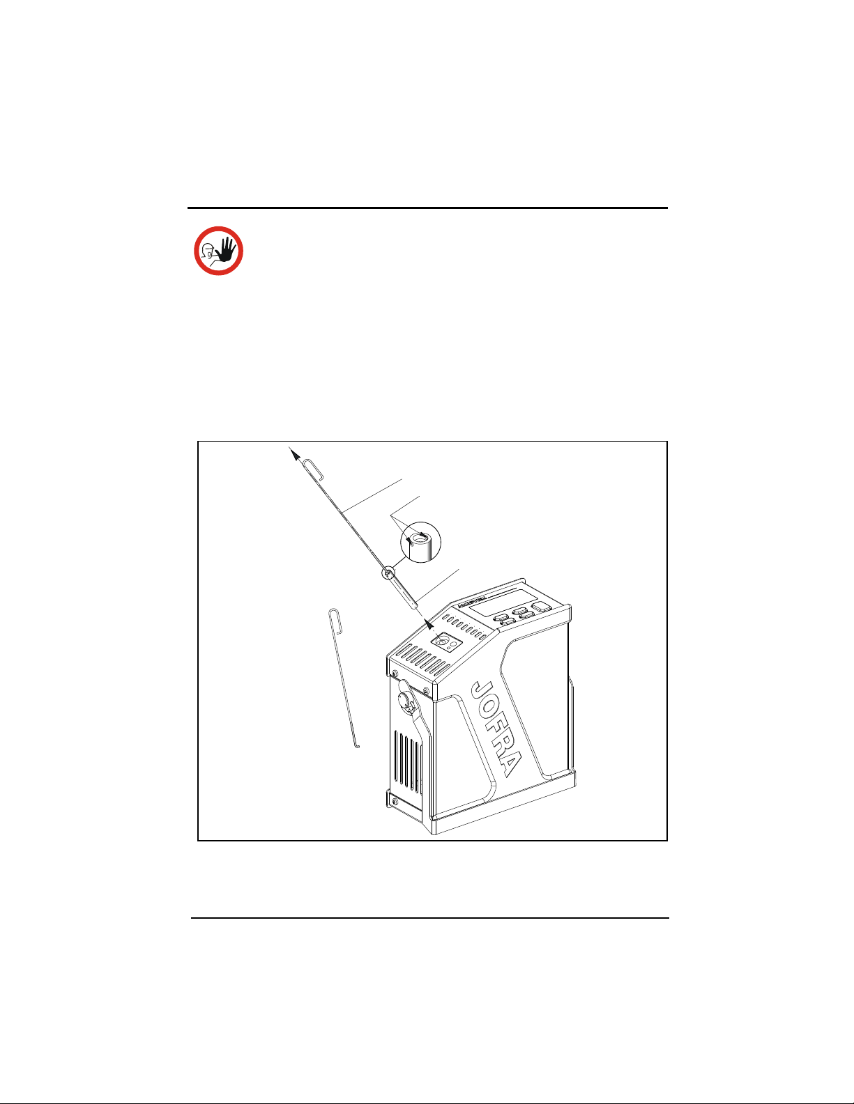
5.0 Storing and transporting the calibrator
Switch off the calibrator using the power control switch.
Note that the calibration procedure may be interrupted at any time
using the power control switch. Switching off the calibrator during the
calibration process will not damage either the instrument or the
sensor.
Caution…
The following guidelines should always be observed when
storing and transporting the calibrator. This will ensure that
the instrument and the sensor remain in good working
order.
Tool for insertion tube
Hole for tool for insertion tube
Insertion tube
Fig. 8
34 2019-04-12 123943 08
Find Quality Products Online at: [email protected]
www.GlobalTestSupply.com
Page 62

ETC-125 A only.
The following routine must be observed before the insertion tube is
removed and the instrument switched off:
Caution – Hot surface
• Over 50°C/122°F
If the calibrator has been heated up to temperatures
above 50°C/122°F, you must wait until the instrument
reaches a temperature below 50°C/122°F before you
switch it off.
• Do not remove the insertion tube from the calibrator
before the insertion tube has cooled down to less than
50°C/122°F
• Never leave hot insertion tubes which have been removed
from the calibrator unsupervised – unauthorized
personnel might pick up insertion tubes causing severe
burns.
• Never place a hot insertion tube in the optional carrying
case.
Below 0°C/32°F
• Do not touch the well or insertion tube when these are
below 0°C/32°F - they might create frostbite.
• If the calibrator has reached a temperature below
0°C/32°F, ice crystals may form on the insertion tube and
on the well. This, in turn, may cause the material
surfaces to oxidize.
To prevent this from happening, the insertion tube and
the well must be dried. This is done by heating up the
calibrator to min. 100°C/212°F until all water left has
evaporated.
It is very important that humidity in the well and insertion
tube is removed to prevent corrosion and frost expansion
damages.
123943 08 2019-04-12 35
Find Quality Products Online at: [email protected]
www.GlobalTestSupply.com
Page 63

Remove the insertion tube from the calibrator using the tool for
insertion tube supplied with the instrument as shown in Fig. 8.
ETC-400 R only
When the ETC-400 R is not in use, it is advisable to store the
calibrator in the carrying case.
Caution…
• The insertion tube must always be removed from the
calibrator after use.
The humidity in the air may cause corrosion oxidation on
the insertion tube inside the instrument. There is a risk
that the insertion tube may get stuck if this is allowed to
happen.
• The insertion tube must be removed to avoid damage to
the instrument if the calibrator is to be transported long
distances.
Caution – Hot surface
• Ove
• You must ensure that the instrument has cooled down to
36 2019-04-12 123943 08
r 50°C/122°F
If the calibrator has been heated up to temperatures
above 50°C/122°F, you must wait until the instrument
reaches a temperature below 50°C/122°F before you
switch it off.
a temperature below 100°C/212°F before placing it in
the carrying case.
Find Quality Products Online at: [email protected]
www.GlobalTestSupply.com
Page 64
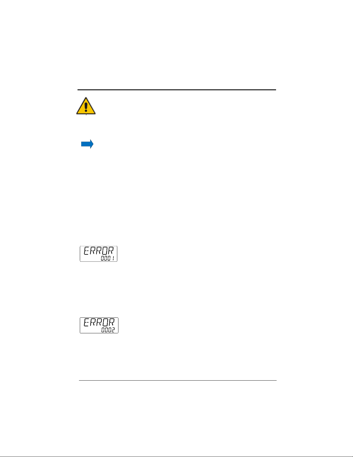
6.0 Errors
If the calibrator detects an error during operation, the instrument will
terminate all functions and display an error code:
Likely cause: Defective RTD-sensor or excessively high
temperature measured by the instrument’s internal
sensor.
Warning
The calibrator must be switched off before any attempt to
service the instrument is made. There are no user
serviceable parts inside the calibrator.
Note…
AMETEK Denmark’s liability ceases if:
• parts are replaced/repaired using spare parts which are
not identical to those recommended by the
manufacturer.
• non-original parts are used in any way when operating
he instrument.
t
AMETEK Denmark’s liability is restricted to errors which
originated from the factory.
Solution: The calibrator should be returned to the
manufacturer for service.
Likely cause: The calibration coefficients have not been accepted.
Solution: Try again. If the error message returns, the
calibrator should be returned to the manufacturer
for service.
123943 08 2019-04-12 37
Find Quality Products Online at: [email protected]
www.GlobalTestSupply.com
Page 65

Likely cause: An error has occurred in the control circuit.
Solution: The calibrator should be returned to the
manufacturer for service.
Nothing happens when the power control switch (on/off
switch) is pressed.
Likely cause: There is no power to the calibrator.
Solution: Check that the calibrator is correctly connected.
If there are no problems with the mains cable, the
calibrator should be returned to the manufacturer
for service.
38 2019-04-12 123943 08
Find Quality Products Online at: [email protected]
www.GlobalTestSupply.com
Page 66

7.0 Returning the calibrator for service
When returning the calibrator to the manufacturer for service, please
enclose a fully completed service information form. Simply copy the
form on the following page and fill in the required information.
The calibrator should be returned in the original packing.
123943 08 2019-04-12 39
Find Quality Products Online at: [email protected]
www.GlobalTestSupply.com
Page 67

Service info
Customer data: Date:
Customer name and address:___________________________________________
Attention and Dept.:___________________________________________________
Fax no./Phone no.:____________________________________________________
Your order no.:_______________________________________________________
Delivery address:_____________________________________________________
Distributor name:_____________________________________________________
Instrument data:
Model and Serial no.:__________________________________________________
Warranty claimed Yes:____ No:_____ Original invoice no.:_________________
___________________________________________________________________
Temp. Se
calibration (please check off):
___ Calibration as left ___ Check
___ Calibration as found and as left ___ Service
___ Accredited calibration as left ___ Repair
___ Accredited calibration as found and as left.
___________________________________________________________________
Diagnosis data/cause for return:
Diagnosis/Fault description:_____________________________________________
___________________________________________________________________
Special requests:_____________________________________________________
___________________________________________________________________
Safety precautions: if the product has been exposed to any hazardous substances, it must be
th
oroughly decontaminated before it is returned to AMETEK. Details of the hazardous
substances and any precautions to be taken must be enclosed.
rvice request: This instrument is sent for
40 2019-04-12 123943 08
Find Quality Products Online at: [email protected]
www.GlobalTestSupply.com
Page 68
8.0 Maintenance
8.1 Cleaning
Caution…
Before cleaning the calibrator, you must switch it off, allow
it to cool down and remove all cables.
Caution – Hot surface
• Over 50°C/122°F
If the calibrator has been heated up to temperatures
above 50°C/122°F, you must wait until the instrument
reaches a temperature below 50°C/122°F before you
switch it off.
Caution – Hot surface – ETC-125 A only
• Do
• Never leave hot insertion tubes which have been removed
• Never place a hot insertion tube in the optional carrying
Below 0°C/32°F
not remove the insertion tube from the calibrator
before the insertion tube has cooled down to less than
50°C/122°F
from the calibrator unsupervised – unauthorized
personnel might pick up insertion tubes causing severe
burns.
case.
• Do not touch the well or insertion tube when these are
below 0°C/32°F - they might create frostbite.
• If the calibrator has reached a temperature below
0°C/32°F, ice crystals may form on the insertion tube and
on the well. This, in turn, may cause the material
surfaces to oxidize.
To prevent this from happening, the insertion tube and
the well must be dried. This is done by heating up the
calibrator to min. 100°C/212°F until all water left has
evaporated.
123943 08 2019-04-12 41
Find Quality Products Online at: [email protected]
www.GlobalTestSupply.com
Page 69

It is very important that humidity in the well and insertion
tube is removed to prevent corrosion and frost expansion
damages.
Caution – ETC-125 A only
The insertion tube must always be removed from the
calibrator after use.
The humidity in the air may cause corrosion oxidation on the
insertion tube inside the instrument. There is a risk that the
insertion tube may get stuck if this is allowed to happen.
Users should/must carry out the following cleaning procedures as
and when required:
• The exterior of the instrument - Clean using water and a soft
cloth.
The cloth should be wrung out hard to avoid any water
penetrating the calibrator and causing damage.
The keyboard may be cleaned using isopropyl alcohol when
heavily soiled.
• The insertion tube (ETC-125 A only) - Must always be clean
and should be regularly wiped using a soft, lint-free, dry cloth.
You must ensure there are no textile fibres on the insertion tube
when it is inserted in the well. The fibres may adhere to the well
and damage it.
• The well - Must always be clean. Dust and textile fibres should
be removed from the well using e.g. compressed air.
Warning
REMEMBER to wear goggles when using compressed air!
• The target unit surface (ETC-400 R only) - Must always be
clean. Dust and textile fibres should carefully be blown from the
surface with clean air. Do not use fluid to clean the target unit
surface.
42 2019-04-12 123943 08
Find Quality Products Online at: [email protected]
www.GlobalTestSupply.com
Page 70

If it is impossible to clean the surface with clean air only the
target unit could alternatively be heated up to max. temperature.
The dust and fibres will then be burned off the surface. There is,
however, the risk that the dust and fibres could permanently burn
into the surface, altering the emission factor.
123943 08 2019-04-12 43
Find Quality Products Online at: [email protected]
www.GlobalTestSupply.com
Page 71
8.2 Adjusting and calibrating the instrument
You are advised to return the calibrator to AMETEK Denmark A/S or
an accredited laboratory at least once a year for calibration and
adjustment.
Alternatively, you can calibrate/adjust the calibrator yourself. You will
need a reference thermometer and a reference sensor with a
traceable calibration certificate. Please follow the instructions given
below.
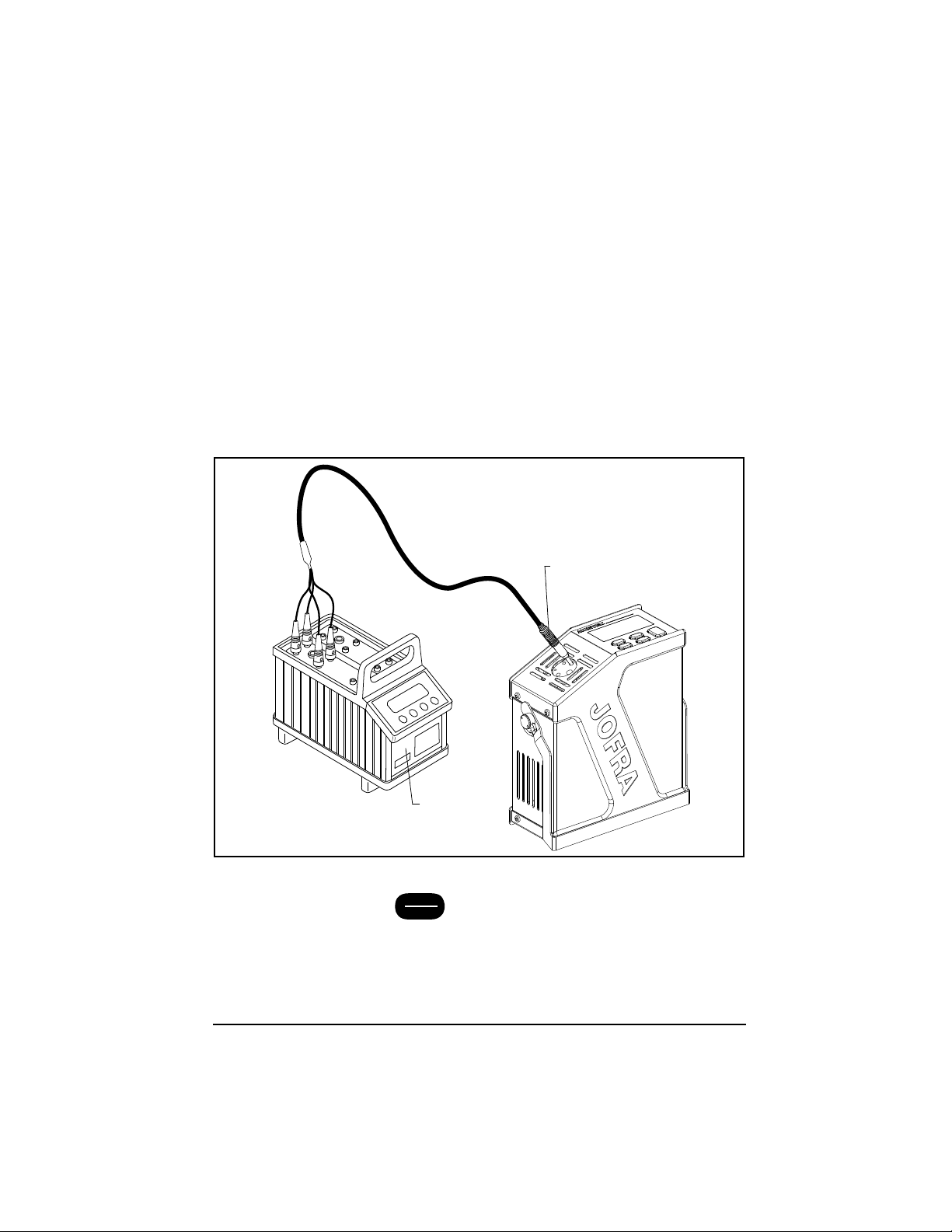
Connect the calibrator to an external precision instrument (e.g. a DTI)
as shown in Fig. 9:
DTI
Sensor
Fig. 9
ESC
Hold down the button while pressing the on/off power
control switch.
MENU
The instrument is now in adjustment/service mode.
44 2019-04-12 123943 08
Find Quality Products Online at: [email protected]
www.GlobalTestSupply.com
Page 72
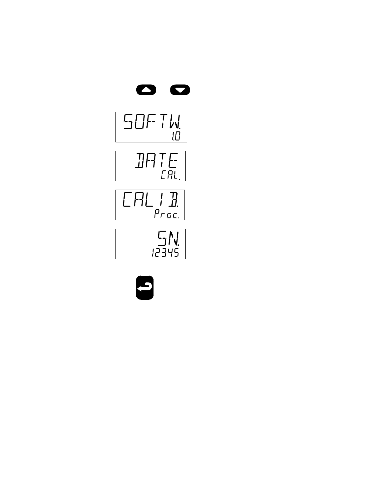
Press or to toggle between the different
options:
To exit the adjustment/service mode, switch the instrument
123943 08 2019-04-12 45
Press
off and on again using the power control switch.
to accept your selection.
Find Quality Products Online at: [email protected]
www.GlobalTestSupply.com
Page 73
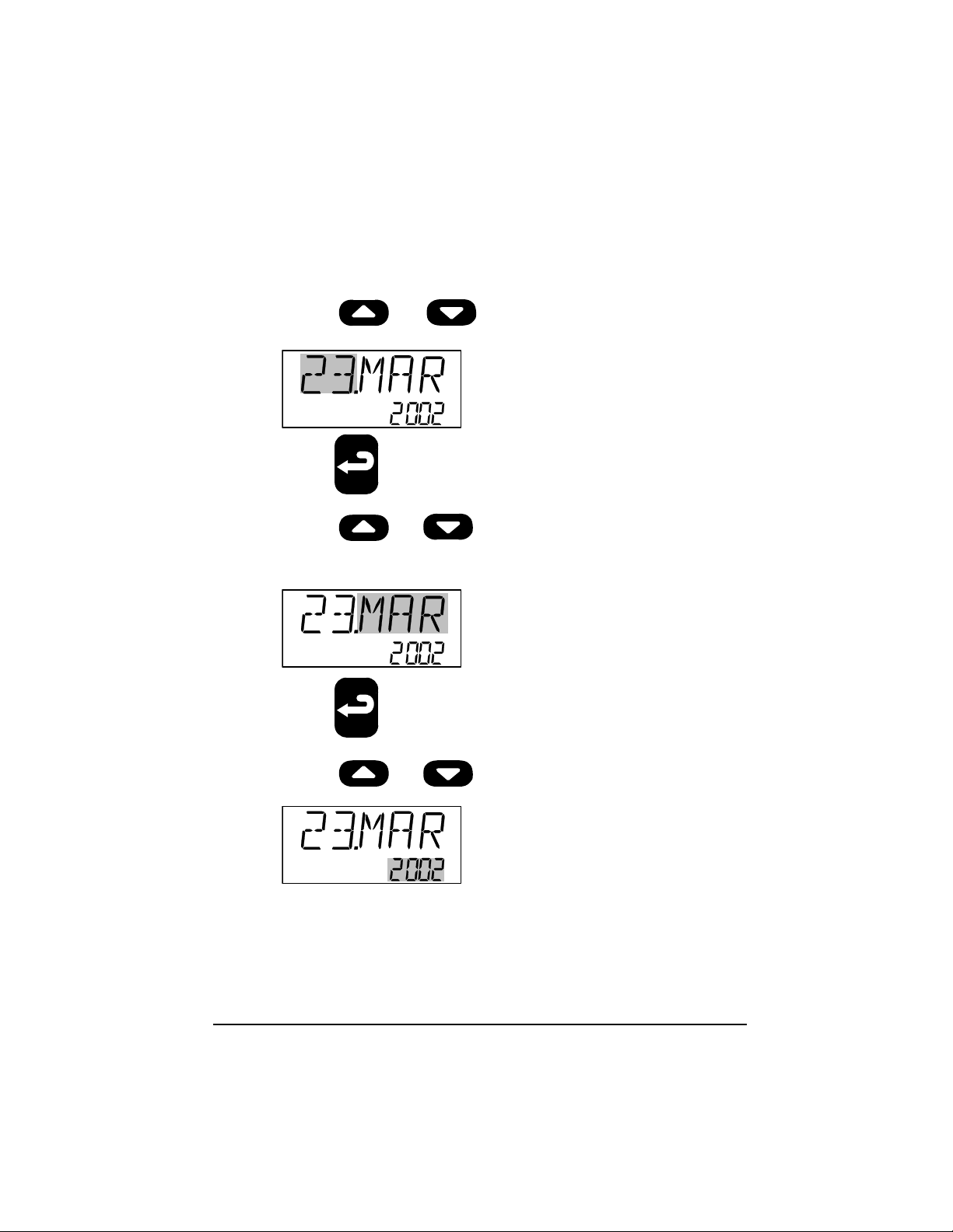
8.2.1 Adjusting the calibration date
Adjust the date by toggling through the available days, months and
years. Begin by selecting the required day as shown below:
Press
interval 1-31.
Press
Pr
JAN / FEB / MAR / APR / MAY / JUN / JUL / AUG / SEP /
OCT / NOV / DEC.
Press
ess
or
to accept your selection.
or
to accept your selection.
to select the required day in the
to select the required month from
46 2019-04-12 123943 08
Press
2025.
Find Quality Products Online at: [email protected]
www.GlobalTestSupply.com
or
to select a year between 2002–
Page 74
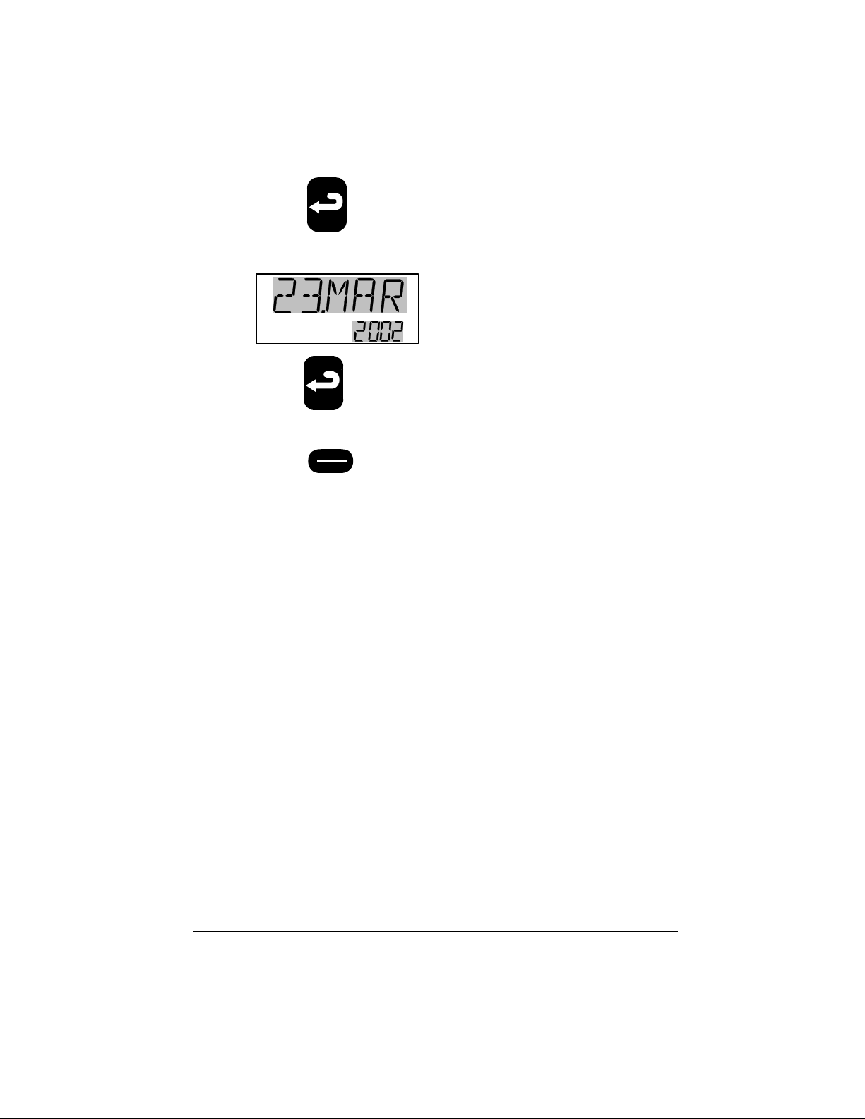
Press
adjusted if necessary to ensure the legality of the date.
Finally, the day, month and year will flash:
to accept your selection. The day will be
or
Press
pr
ess
to accept the date.
ESC
MENU
to cancel the whole selection.
8.2.2 Calibrating/adjusting the instrument
The internal calibration/adjustment is a complex function which is
divided into a number of different steps:
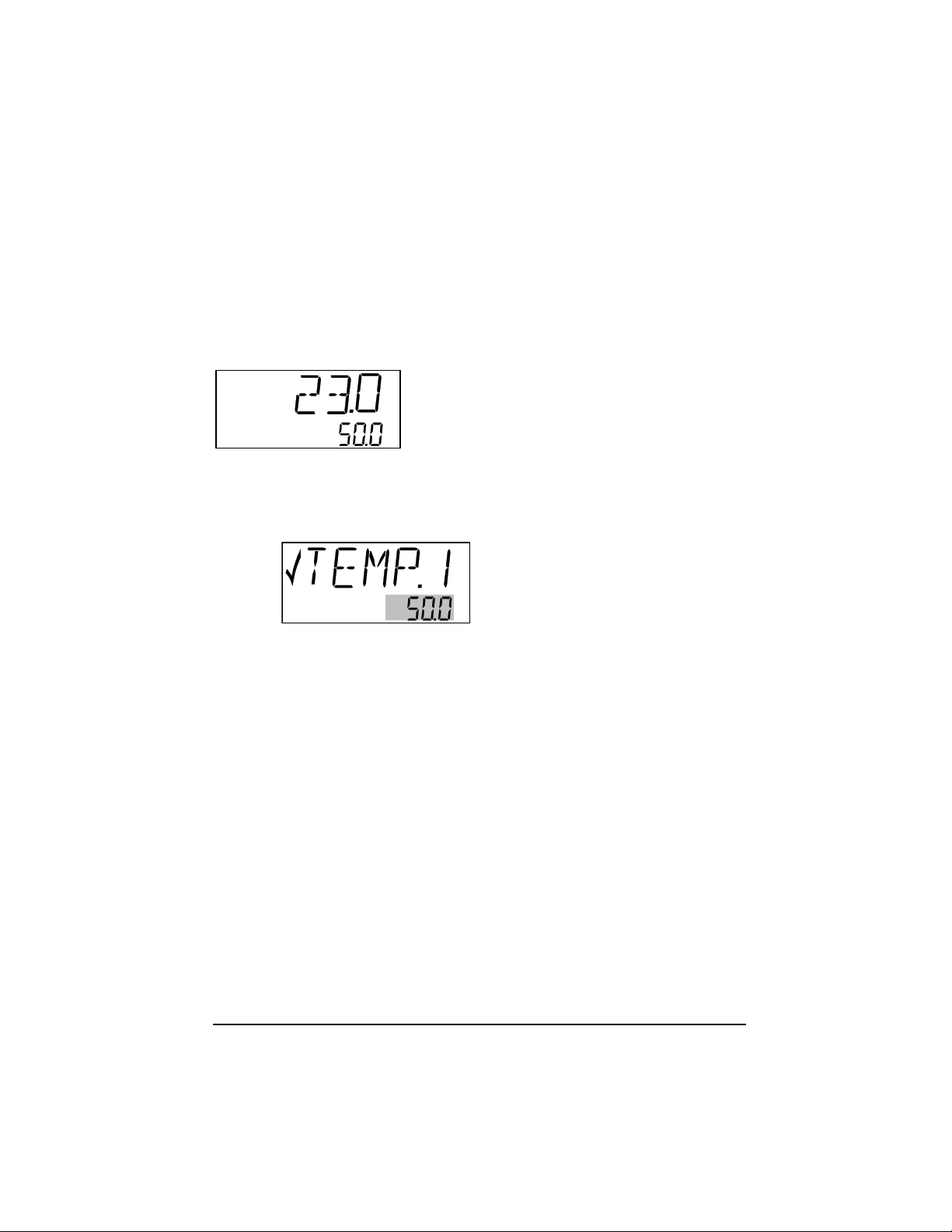
The instrument will disclose the first calibration temperature by
displaying the text “TEMP.1 XXX°C” for approx. 1 second:
Calibration temperature for calibrators:
ETC-125 A 1. -8°C / 17.6°F
2. 0°C / 32°F
3. 50°C / 122°F
4. 100°C / 212°F
5. 125°C / 257°F
123943 08 2019-04-12 47
Find Quality Products Online at: [email protected]
www.GlobalTestSupply.com
Page 75
ETC-400 A / R 1. 50°C / 122°F
°C
2. 100°C / 212°F
3. 200°C / 392°F
4. 300°C / 572°F
5. 400°C / 752°F
The instrument will now heat up/cool down to reach the first
calibration temperature:
°C
ce the calibrator is stable, you need to enter the reference
On
temperature found using the reference thermometer. The
calibration temperature is suggested as a reference point:
°C
This procedure is repeated for TEMP.2, TEMP.3, TEMP.4 and
TEMP.5.
All five calibration temperatures and associated reference
temperatures have now been entered.
The instrument will now check whether the reference temperatures
which have been entered are within the permitted tolerances.
Permitted tolerances:
• ETC-125 A / 400 A / 400 R : ±0,2°C / 0.36°F
48 2019-04-12 123943 08
Find Quality Products Online at: [email protected]
www.GlobalTestSupply.com
Page 76
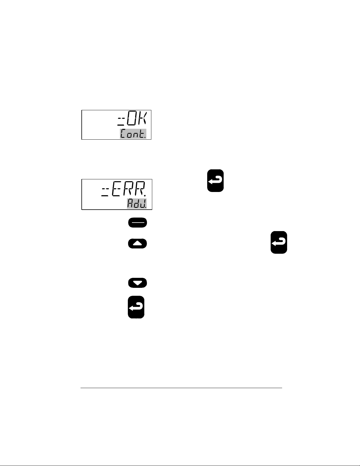
If the calibrator is found to be within the permitted tolerances, the
instrument will display the text =OK at the top of the display. The text
Cont. will flash in the bottom of the display to indicate that you may
continue without adjustments:
If the instrument detects excessive deviations for one or more steps,
it will show a screen reading =ERR. in the top of the display. The text
AdJ. will flash in the bottom of the display to indicate that an
adjustment is required. Accept by pressing .
Press
Press
to repeat an adjustment step when it is shown on the
display.
Press
display.
Press
coefficients. Next, repeat the entire calibration/adjustment
procedure.
ESC
to cancel the adjustment function.
MENU
to go back to a previous screen and press
to toggle between AdJ. and Cont. on the
when AdJ. is flashing to calculate a new set of
123943 08 2019-04-12 49
Find Quality Products Online at: [email protected]
www.GlobalTestSupply.com
Page 77

If the new coefficients deviate by more than 4% from the
standard values, the instrument will display an ERROR 2 in
the display. The calculated coefficients will be ignored:
Press
procedure.
Press
calibration/adjustment procedure and enter a new calibration
date (see section 8.2.1).
to repeat the entire calibration/adjustment
when Cont. is flashing to end the
50 2019-04-12 123943 08
Find Quality Products Online at: [email protected]
www.GlobalTestSupply.com
Page 78
8.2.3 Calibrating/adjusting the ETC-400 R
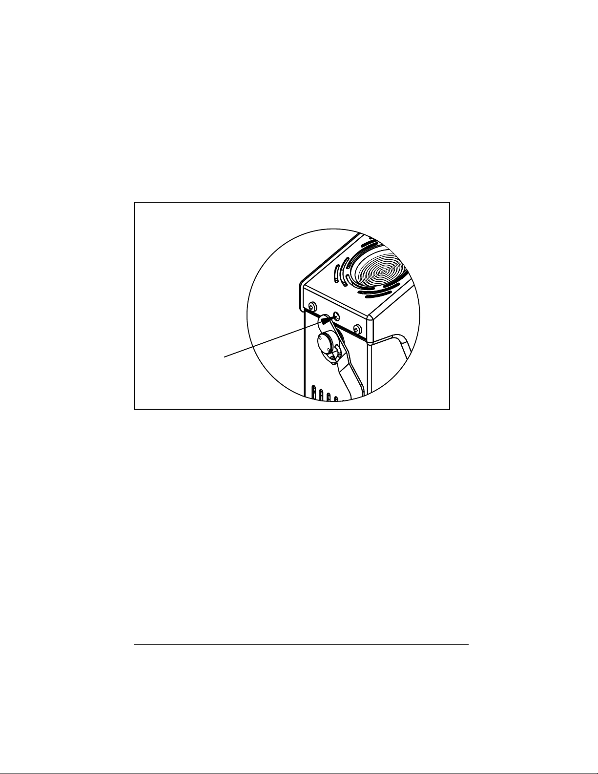
In order to calibrate the inner thermometer of the calibrator, a 3 mm
insertion hole for the reference sensor has been drilled 1 mm
beneath the target unit surface. See fig. 10.
Insertion hole for
th
e reference sensor
Fig. 10
For the calibration it is recommendable to use the RTD reference
sensor 65-Pt100-150 SPEC. which AMETEK DENMARK A/S has
developed specifically for this instrument.
In principle any sensor fitting the insertion hole is useable, however,
there is the risk of incorrect temperature reading due to the limited
insertion depth of the reference sensor hole.
123943 08 2019-04-12 51
Find Quality Products Online at: [email protected]
www.GlobalTestSupply.com
Page 79
9.0 Technical specifications
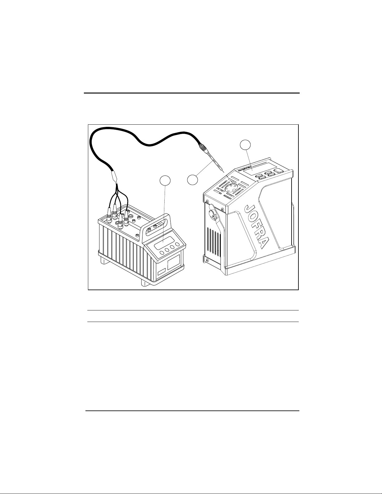
The illustration below shows the setup which forms the basis for the
technical specifications. In this case an ETC-400 A.
Fig. 11
Description
Pos.
3
2
1
52 2019-04-12 123943 08
Find Quality Products Online at: [email protected]
Calibrator
ø4 mm Pt 100 sensor with traceable certificate (ETC-
125/400 A)
ø3mm Pt 100 sensor with traceable certificate (ETC-400
R)
DTI 1000 reference precision thermometer with traceable
cer
tificate
www.GlobalTestSupply.com
Page 80

Thermal specifications
All specifications are given with an ambient temperature of 23°C/73.4°F ±
3°C/5.4°F.
1
Measured at the bottom of the well with a 4 mm sensor
2
Specified at 115V / 230V
Specifications Model
ETC-125 A
Max. temperature : 125°C / 257°F
Min. temperature : -18°C / -0.4°F @ ambient temperature 0°C / 32°F
-10°C / 14°F@ ambient temperature 23°C / 73.4°F
6°C / 42.8°F @ ambient temperature 40°C / 104°F
l specifications : 40 mm / 1.57 in. axial homogeneity :
Wel
0.30°C / 0.54°F @ -10°C / 14°F
0.85°C / 1.53°F @ 125°C / 257°F
60 mm / 2.36 in. axial homogeneity :
0.30°C / 0.54°F @ -10°C / 14°F
0.85°C / 1.53°F @ 125°C / 257°F
Difference between borings :
0.40°C / 0.72°F
Influence from load :
0.10°C / 0.18°F @ -10°C / 14°F
0.20°C / 0.36°F @ 125°C / 257°F
Display resolution : 1° or 0.1°C / 1.8° or 0.18°F
Stability : ±0.05°C / ±0.09°F
Accuracy
1
: ±0
.5°C / ±0.9°F
Heating time 2 : -10
23 to 100°C / 73 to 212°F : 11 min.
100 to 125°C / 212 to 257°F : 7 min.
to 23°C / 14 to 73°F : 3 min.
123943 08 2019-04-12 53
Find Quality Products Online at: [email protected]
www.GlobalTestSupply.com
Page 81

ETC-125 A
Time to stability: 3 minutes
Cooling time : 125 to 100°C / 257 to 212°F : 1 min.
100 to 0°C / 212 to 32°F : 17 min.
0 to -10°C / 32 to 14°F : 14 min.
ETC-400 A
Max. temperature : 400°C / 752°F
Min. temperature : 5°C / 41°F @ ambient temperature 0°C / 32°F
28°C /82.4°F@ ambient temperature 23°C/ 73.4°F
45°C / 113°F @ ambient temperature 40°C /104°F
l specifications : 40 mm / 1.57 in. axial homogeneity :
Wel
0.85°C / 1.53°F @ 180°C / 356°F
1.00°C / 1.8°F @ 400°C / 752°F
Difference between borings :
0.40°C / 0.72°F
Influence from load :
0.30°C / 0.54°F @ 400°C / 752°F
Display resolution : 1° or 0.1°C / 1.8° or 0.18°F
Stability : ±0.15°C / ±0.27°F
Accuracy 1 : ±0.5°C / ±0.9°F
Heating time 2 : 28 to 200°C / 82 to 392°F : 2 min.
200 to 400°C / 392 to 752°F : 3 min.
Time to stability: 3 minutes
Cooling time : 400 to 200°C / 752 to 392°F : 6 min.
20
0 to 50°C / 392 to 122°F : 15 min.
54 2019-04-12 123943 08
Find Quality Products Online at: [email protected]
www.GlobalTestSupply.com
Page 82

ETC-400 R
Max. temperature : 400°C / 752°F
Min. temperature : 5°C / 41°F @ ambient temperature 0°C / 32°F
28°C /82.4°F@ ambient temperature 23°C/ 73.4°F
45°C / 113°F @ ambient temperature 40°C /104°F
Display resolution : 1° or 0.1°C / 1.8° or 0.18°F
Stability : ±0.3°C / ±0.54°F
Accuracy : ±0.5°C / ±0.9°F
Accuracy incl.
emissivity : ±0.4% rdg. ±1°C / ±0.4% rdg. ±1.8°F
Heating time 2 : 28
200 to 400°C / 392 to 752°F : 3 min.
Time to stability: 3 minutes
Cooling time : 400 to 200°C / 752 to 392°F : 9 min.
200 to 50°C / 392 to 122°F : 24 min.
Emissivity : 0.96
to 200°C / 82 to 392°F : 2 min.
123943 08 2019-04-12 55
Find Quality Products Online at: [email protected]
www.GlobalTestSupply.com
Page 83

Electrical specifications
Specifications Model
ETC-125 A
Power supply [VAC]: Multivoltage 115VAC and 230VAC, 47-63Hz
115 V (90-132) and 230 V (180-264)
Power
consumption (max.): 75 VA
ETC-400 A / R
Power supply [VAC],
115VAC, 45-65Hz : 90-127
230VAC, 45-65Hz : 180-254
er
Pow
consumption (max.): 350 W
Mechanical specifications
Specifications Model
ETC-125 A
Weight : 1.75 kg. / 3.86 lb.
Dimensions
LxWxH : 172 x 72 x 182 mm / 6.8 x 2.8 x 7.2 inch
Operating temp. : 0 to 40°C / 32 to 104°F
Storage temp. : -20 to 50°C / -4 to 122°F
idity range : 0 to 90% RH
Hum
Pro
tection class : IP10
56 2019-04-12 123943 08
Find Quality Products Online at: [email protected]
www.GlobalTestSupply.com
Page 84

ETC-400 A / R
Weight : 1.58 kg. / 3.5 lb. (ETC-400 A)
1.7 kg. / 3.7 lb. (ETC-400 R)
Dimensions
LxWxH : 172 x 72 x 182 mm / 6.8 x 2.8 x 7.2 inch
Operating temp. : 0 to 40°C / 32 to 104°F
Storage temp. : -20 to 50°C / -4 to 122°F
Humidity range : 0 to 90% RH
Protection class : IP10
STANDARDS – ALL MODELS
The following standards are observed
according to the EMC-Directive
(2014/30/EU)
The following standards are observed
according to the low voltage-directive
(2014/35/EU)
EN 61326-1: 2013: Electrical equipment for
measurement, control and laboratory use –
EMC requirements.
EN61010-1:2010 : Safety requirements for
electrical equipment for measurement, control
and laboratory use, part 1: General requirement
123943 08 2019-04-12 57
Find Quality Products Online at: [email protected]
www.GlobalTestSupply.com
Page 85

10.0 List of accessories
All parts listed in the list of accessories can be obtained from the
factory through our dealers.
Please contact your dealer for assistance if you require parts which
do not appear on the list.
List of accessories
Accessories Parts no.
User and reference manual 123943
Tool for insertion tube (ETC-125 A only) 60F172
Aluminium carrying case 124094
Mains cable, 115V, US, type B 60F135
Mains cable, 240V, UK, type C 60F136
Mains cable, 220V, South Africa, type D 60F137
Mains cable, 220V, Italy, type E 60F138
Mains cable, 240V, Australia, type F 60F139
Mains cable, 230V, Europe, type A 60F140
Mains cable, 230V, Denmark, type G 60F141
Mains cable, 220V, Switzerland, type H 60F142
Mains cable, 230V, Israel, type I 60F143
RS232 serial cable 2 m 123958
5 x undrilled insertion tubes for ETC-125 A 123939
8 mm / 5/16 inch insertion tube for ETC-125 A 123938
3/8 inch insertion tube for ETC-125 A 124045
Shoulder strap with snap hooks 124004
JOFRACAL PC software 124915
JOFRA IR-LAB calibration software for ETC-400 R 124591
Correction table for emissivity for ETC-400 R 124592
Pt100 sensor ø3mm x 150mm for ETC-400 R 65-PT100-150 SPEC
58 2019-04-12 123943 08
Find Quality Products Online at: [email protected]
www.GlobalTestSupply.com
Page 86

AMETEK Sensors, Test & Calibration
A busine ss unit of A METEK Measure ment &
Calibration Technologies Division offering the
followi ng industry leading bran ds for test and
Portable dry-block calibrators, precision
therm ometer s and liqui d baths. Tempe rature
Conveni ent elec tronic sy stems ra nging fro m
-25 mbar to 100 0 bar - full y temperature-
compensated for problem-free and accurate
Process signal measurement an d simulat ion for
easy control loo p calibration and m easure ment
Pneumatic floating-ball or hydraulic piston dead
weight te sters wi th accur acies to 0.015% of
readin g. Pressure generators de liverin g up to
Digital press ure gaug es and cal ibrator s that are
accurate, easy-to -use an d reliable. Designed for
use in the h arshe st enviro nments ; most pr oducts
Materials testing machines and software that
guara ntees exp ert materials te sting so lutions .
Also covering Textur e Analys ers to perform r apid,
gener al food testing and d etaile d texture a nalysis
on a diver se range o f foods an d cosmetics.
The han d held forc e gauges and motor ized
tester s have earn ed their r eputation for qua lity,
reliab ility an d accura cy and they r eprese nt the de
facto standard for force measurement.
Hardness testers, durometers, optical systems
and sof tware fo r data acq uisitio n and analysis.
calibration instrumentation.
JOFRA Calibration Instruments
Temperature Calibrators
sensors for industrial and marine use.
M&G Deadweight Testers & Pu mps
carr y an IS, IP67 a nd DNV rat ing.
Chatillon Force Measurement
Pressure Calibrators
field use.
Signal Instruments
tasks.
1,000 bar.
Crystal Pressure
Lloyd Materials Testing
Newage Hardness Testing
Find Quality Products Online at: [email protected]
www.GlobalTestSupply.com
 Loading...