

Page 1
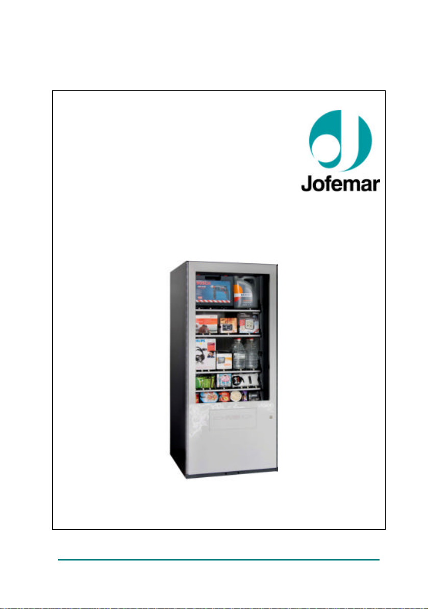
Vision Es-Plus // Vending
English
vision ES-PLUS
MNP141GBV00 Date: 2011/04/29 Rev. 0 PAGE 1 OF 24
TECHNICAL MANUAL
Page 2
Vision Es-Plus // Vending
F WARNING!
Read the following instructions carefully before using your machine:
? Remove plastic plugs from bottom of machine and place it on the floor before
opening and unpacking.
? When discarding packaging material or an old machine, please consult about
recycling.
? Since the machine has a cooling unit, it should be transported in vertical position
and it should not be connected to mains until 2 hours have elapsed after concluding
the unpacking and installation process.
? Before connecting to mains, make sure that the power supply characteristics
coincide with those of the machine.
? The power cable plug should be installed so the machine can be easily
disconnected from mains.
? Place a rub ber protection around the power cable in the slot of the lid of the cable
winding recess.
? Do not burn or throw away the battery. Batteries should be disposed of in
accordance with local laws and regulations and may be recyclable.
? Protect the machine against humidity, dust, dirt, etc. You should particularly avoid
any obstruction of the ventilation grids.
? Do not clean the machine with concentrated products as they may attack the
painted and wood surfaces and alter the colour.
? Frequent cleaning, can prevent breakdowns and extend the machine's service life .
? The machine should be installed in a vertical position, with a maximum back to
front or lateral tilt of 5% (~2°).
? If you need to replace the power supply cable, please replace it with the
appropriate one for your country:
If the power cable is damaged, it should be replaced by the manufacturer or
after sales service or similar qualified personnel to prevent hazards.
Jofemar S.A.
Ctra. de Marcilla Km.2, 31350 PERALTA. Navarra, SPAIN.
http: // www.jofemar.com Tel. +34 948 75 12 12 Fax +34 948 75 04 20
MNP141GBV00 Date: 2011/04/29 Rev. 0 PAGE 2 OF 24
Page 3

Vision Es-Plus // Vending
ÍNDICE
1. Symbols...............................................................................................................4
2. Operating conditions..........................................................................................4
3. Description of components...............................................................................4
3.1. Main technical features...........................................................................6
3.1.1 Door......................................................................................................6
3.1.2 Cabinet.................................................................................................6
3.2. Volume and weight................................................................................11
4. Electric-electronic specifications ~...............................................................12
4.1. Initial electrical installation ~..............................................................12
4.2. Product dispenser channel..................................................................13
4.3. Control card............................................................................................13
4.4. Relay card ...............................................................................................14
4.5. Electronic thermometer card...............................................................14
4.6. Elevator product detector photocell cards.........................................14
4.7. Electronic control system .....................................................................14
4.8. Machine electrical drawing...................................................................16
5. Installation and start up...................................................................................17
5.1. Installation...............................................................................................17
5.2. Start up....................................................................................................17
5.3. Restocking machine trays....................................................................17
5.4. Updating the machine program...........................................................18
6. Operation...........................................................................................................19
7. Troubleshooting................................................................................................19
8. Annexes.............................................................................................................21
8.1. Transport feet and adjustable levelling feet......................................21
8.2. Cleaning and Maintenance..................................................................21
8.3. Recyclable..............................................................................................22
8.4. Environment ................................................................................23
9. Regulation.........................................................................................................23
MNP141GBV00 Date: 2011/04/29 Rev. 0 PAGE 3 OF 24
Page 4
Vision Es-Plus // Vending
1. Symbols
i This symbol means there are more detailed explanations on this subject
elsewhere in the manual.
è This symbol means that the text in question refers to programming.
F This symbol indicates very important information.
~ This symbol is a warning of high voltage hazard.
This symbol indicates that a given material should not be disposed of as
domestic waste.
This symbol indicates that a given material is recyclable.
This symbol indicates that Jofemar is committed to the environment.
2. Operating conditions
This machine has been specifically designed to work in interiors. The machine leaves the
factory adjusted to work properly at an ambient temperature between 5º C (41º F) y 32º
C (89.6º F)5° C and 32° C with a maximum humidity of 60% and a maximum load of 100
kg (220 lb) of products.
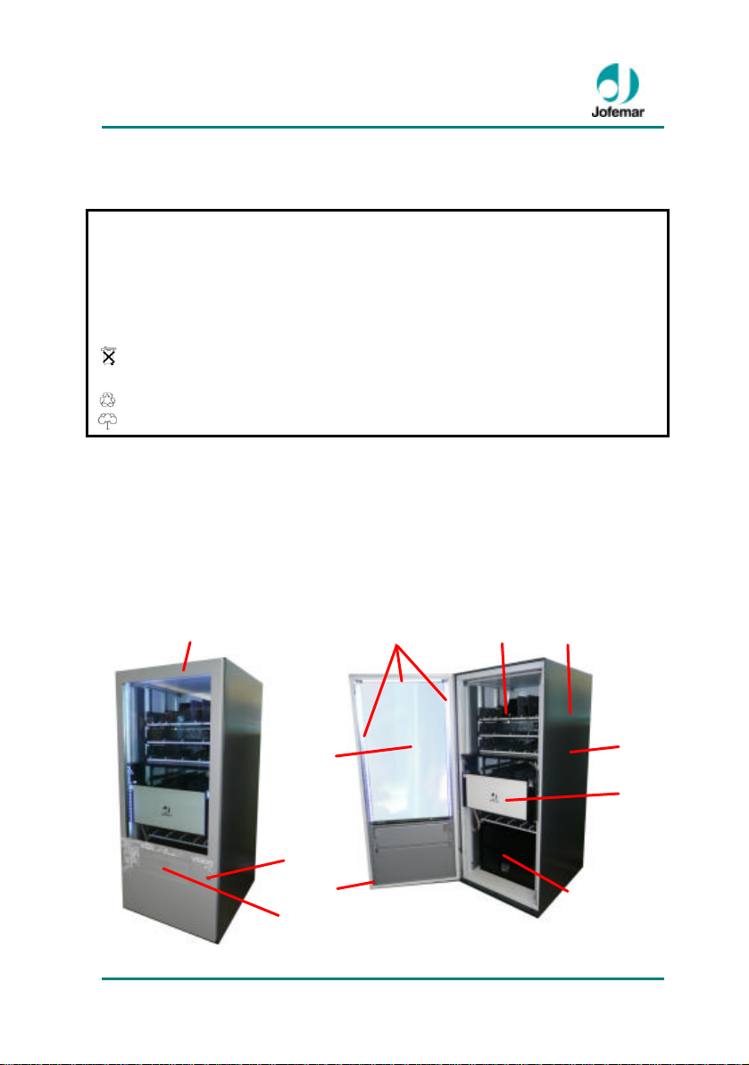
3. Description of components
MNP141GBV00 Date: 2011/04/29 Rev. 0 PAGE 4 OF 24
A
C
B
D
E
I
G
F
K/L/M/N/Ñ
H
O
Page 5
Vision Es-Plus // Vending
O
Ñ
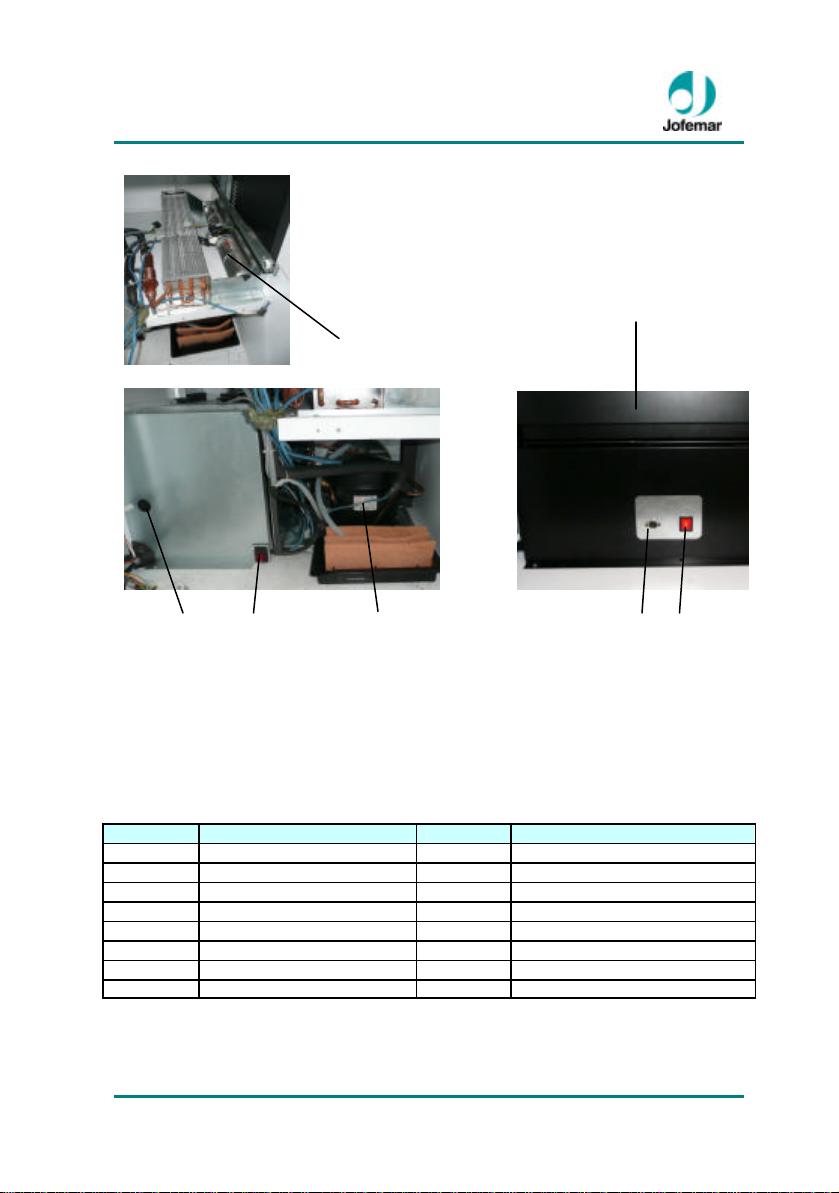
WITH COOLING UNIT WITHOUT COOLING UNIT
WITH COOLING UNIT WITHOUT COOLING UNIT
Posición Descripción Posición Descripción
A Door I Door microswitch
B Lock J Electronics support
C Product delivery opening K RS-232 connection
D Safety glass L Fuse/Fuse holder
E Iluminación Leds M Main switch
F Cabinet N Cooling unit
G Trays and channels Ñ Turbine
H Elevator O Photocell scanning assembly
MNP141GBV00 Date: 2011/04/29 Rev. 0 PAGE 5 OF 24
M M K K
MAIN SWITCH POSITION AND RS-232 CO NNECTOR
N
Page 6
Vision Es-Plus // Vending
3.1. Main technical features
? Dispenses a wide range of products of different sizes and shapes —different types of
drinks and snacks, sandwiches, different objects, glass bottles, bread, egg cartons, etc.
? Flexible configuration and programming, up to 8 height-adjustable trays with up to 10
channels each for including various product formats.
? Adjustable internal temperature.
? The metal parts are constructed in 0.8 mm (0.031") thick galvanized steel, with outer a
weather-proof PVC coating.
3.1.1 Door
The metal parts are constructed in 1,2 mm (0.047”) thick galvanised steel, with rustproof
protection and an external coat of rustproof paint.
On the front of the door you can see the following: the safety glass, lock and product
delivery outlet. On the back of the door you can see: the door microswitch, three LED
strips, and the product delivery door stop.
Safety glass
Made of double glazed, low emission climalit safety glass with a
12 mm (0.472 “) gap offering top strain reliability.
It provides a view of the products and their location on the trays.
Fig. 01
Lock
These machines feature a secure locking system consisting of a plate with three vandalproof anchoring points.
3.1.2 Cabinet
The cabinet holds the product trays, the vault, the electronic control system, the cooling
unit (for vision Easy Combo) and the product delivery bin.
The structure of the cabinet is injected with polythene foam for improved insulation and
better consistency.
MNP141GBV00 Date: 2011/04/29 Rev. 0 PAGE 6 OF 24
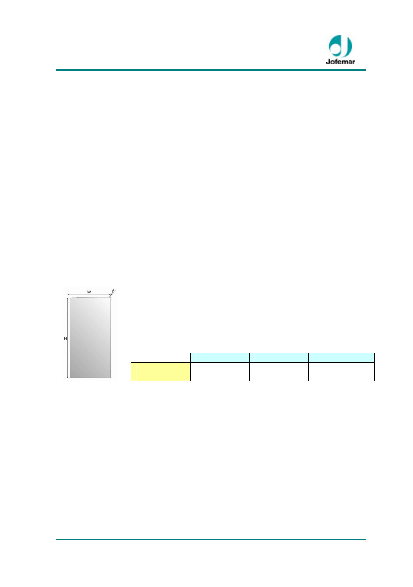
Height (H) Width (W) Thickness (F)
Vision Es-
Plus
1.169,5 mm.
(46.043”)
714 mm.
(28.043”)
22 mm
(0.866”)
Page 7
Vision Es-Plus // Vending
Trays and channels
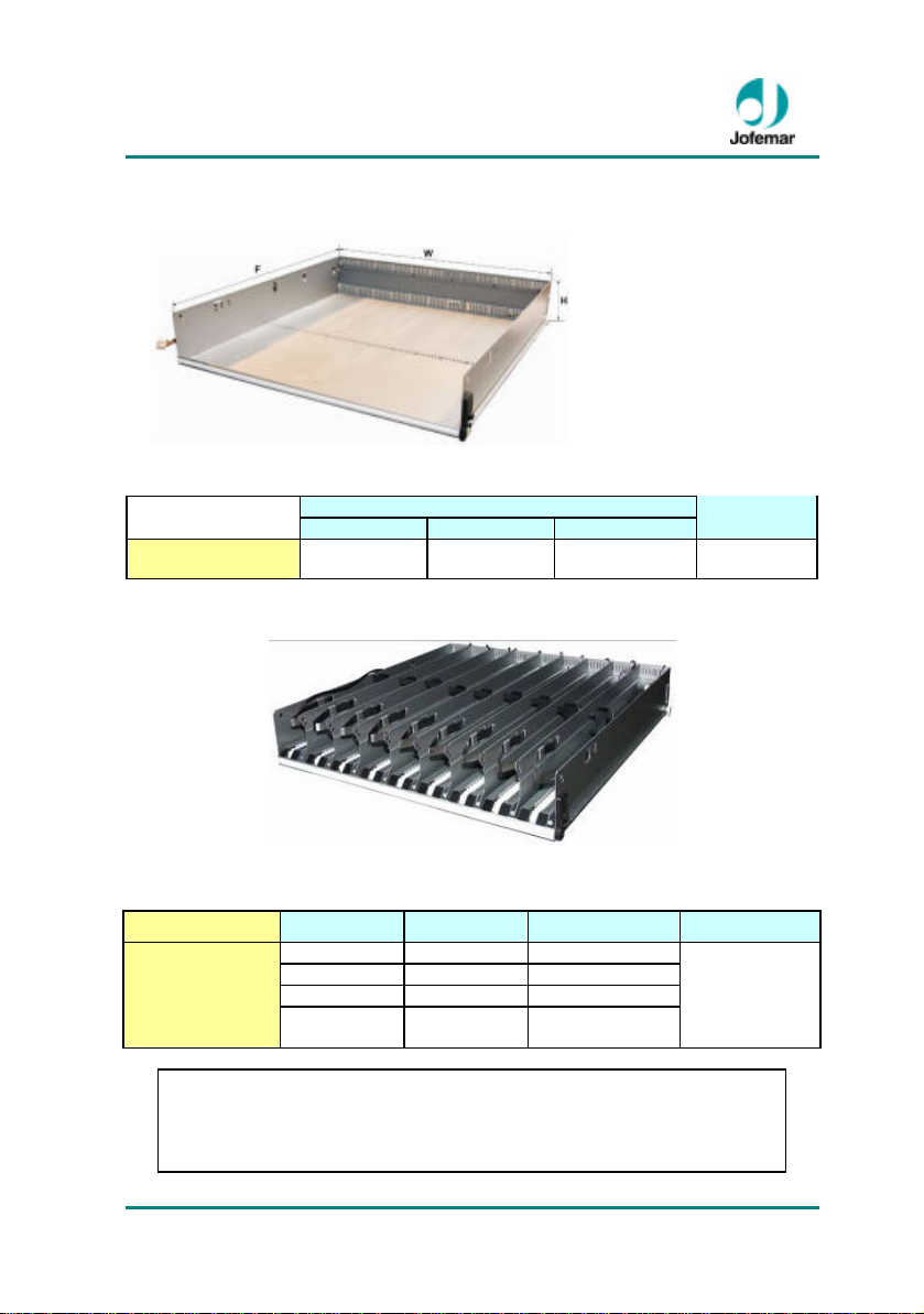
TRAYS
Large
Capacity up to 10 channels per tray depending on configuration.
Fig. 02
Height (H) Width (W) Depth (D)
115 mm
(4.527”)
Large tray with 1 to 10 channels
Dimensions
642,2 mm
(25.283”)
There are two types of
trays and they are the part
of the machine where the
product is stored, as there
are various configurations,
one machine can have up
to 8 trays maximum
depending on the products
that you wish to dispense.
675 mm
(26.574”)
Weight
5,250 Kg
11.55 lb
The vision machines sell the products shown in the following table:
vision
Vision Es-Plus
IMPORTANT: The minimum size for dispensing in this machine is the size of
MNP141GBV00 Date: 2011/04/29 Rev. 0 PAGE 7 OF 24
Fig. 03
SNACKS DRINKS SANDWICHES PRODUCTS
Sachets Cans
Sweets Bottles
NOTE: For other types of products or special sizes please contact your
a tobacco package 23mm x 55mm x 88mm (0.905” x 2.165” x 3.465”).
Pastries Tetra bricks Of any type
Chocolates Dairy
products
Jofemar distributor.
Large Products
Page 8

Vision Es-Plus // Vending
i Electronic control system
It consist of several printed circuit cards:
• Control card, which governs all of the machine’s movements, and contains the
power supply that provides the appropriate voltages for the logic control to move the
trays motor, to move the elevator motor to move the motor the verifier of the product
detector and to feed the product detection system. The program is recorded in
FLASH memory
• Relay card, which has the relays that control the connection to the compressor,
electrovalve and showcase light.
• Photodiode and phototransistor cards of the product detection system.
• Photodiode and phototransistor cards to control the position of elevator.
• Electronic thermometer card for machines with refrigeration unit.
i R 134A CFC-free cooling unit (Es-Plus )
It is managed by a program which controls the temperature of the machine product hold
electronically.
The machine is equipped with a cooling unit and a turbine to keep a constant working
temperature in the product hold. This temperature, also called cooling unit cut-off
temperature, is programmable on the master machine. When the internal temperature
rises 2.5 °C (36.5º F) above the cooling unit cut-off temperature, the cooling unit turns
on. When the internal temperature again matches the cut-off temperature, the cooling
unit turns off.
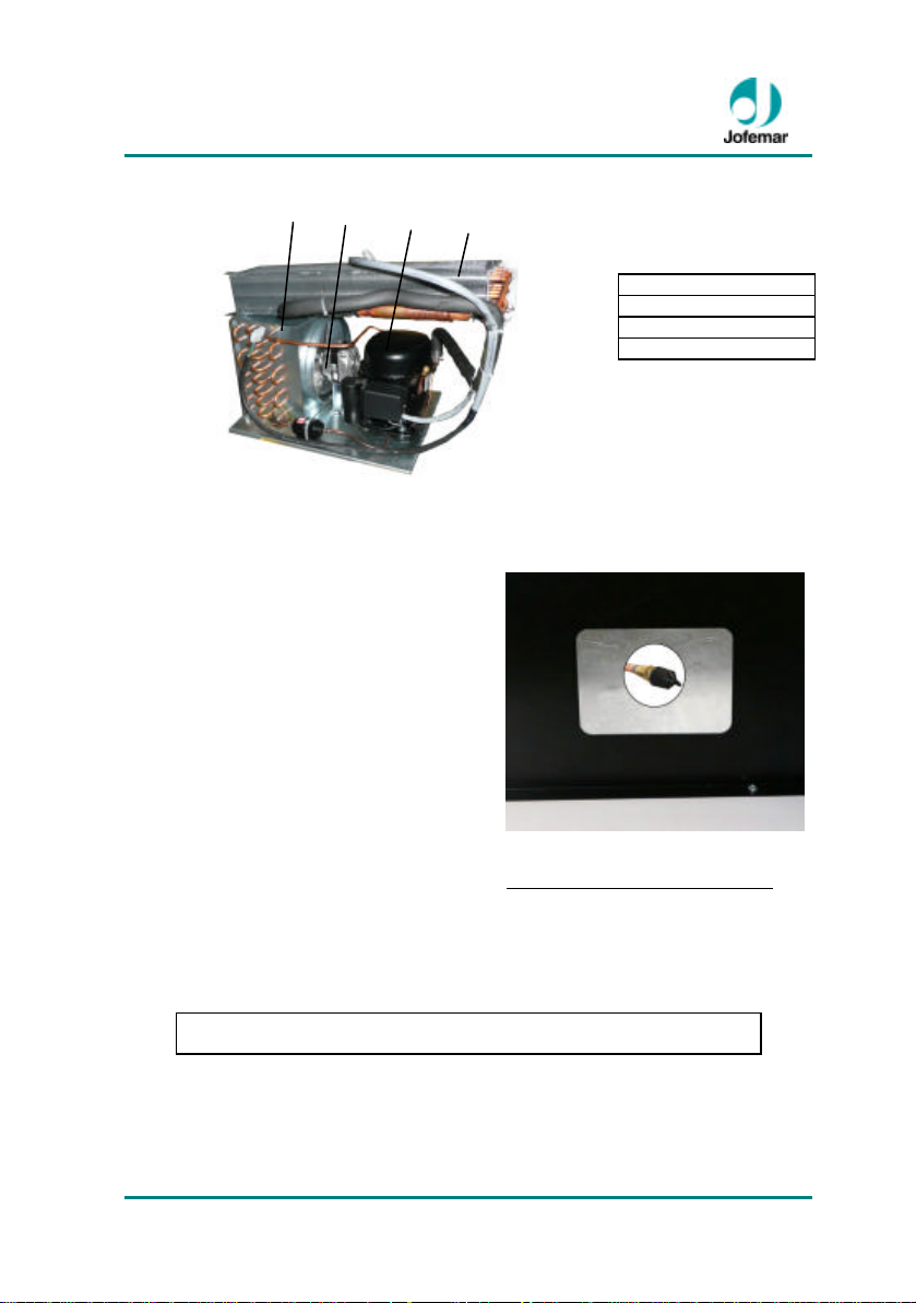
The cooling unit consists of a compressor and a condenser located in the lower part of
the cabinet, as well as an evaporator located inside the product hold and an axial flow
fan that cools the condenser and the compressor motor. The cooling gas used is the gas
indicated on the machine compressor. The turbine is a fan with two runners located
inside the product hold which is permanently in operation.
MNP141GBV00 Date: 2011/04/29 Rev. 0 PAGE 8 OF 24
Page 9
Vision Es-Plus // Vending
A
B C D
To
A. Condenser
B. Fan
C. Compressor
D. Evaporator
Fig. 04
The machine carries out defrosting cycles to prevent ice from building up in the
evaporator of the cooling unit, which would have adverse effects on the unit’s
performance. The defrosting cycle consists of turning the cooling unit off long enough for
the ice build-up on the evaporator to disappear. A total of 3 defrosting cycles are carried
out a day at approximately 8-hour intervals. The unit is further defrosted three hours after
the machine has been restocked with product; in this case the internal temperature will
not be shown on the display until one hour after the defrosting cycle began.
There is a window to permit air circulation
through the inside area where the compressor
and condenser are located. It is located at the
back of the machine cabinet. For proper
operation of the cooling system the window
should be kept free of dust and you should
check regularly that it is not obstructed by
foreign objects, such as bags, papers, etc.
The indoor temperature can be programmed
in the MASTER level machine option between
0.5 °C (32.9 °F) and 12 °C (53.6 °F).
Note: For safety reasons, every time the unit is stopped and started, the
process is detained during a 4-minute interval.
Fig. 05
GROUP PRESSURE TESTING
check the pressure of the cooling unit,
remove the black cap, where the head
of the core is located. Connecting a
pressure gauge and get a pressure
reading.
Elevator
MNP141GBV00 Date: 2011/04/29 Rev. 0 PAGE 9 OF 24
Page 10
Vision Es-Plus // Vending
LEDS
w H F
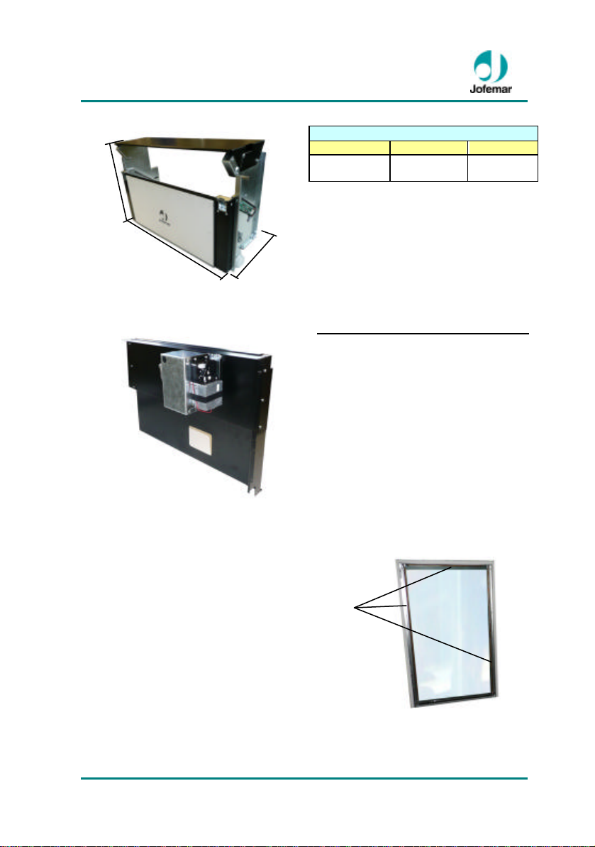
Height (H) Width (W) Depth (D)
455 mm
(17.913”)
It has a product detection system based
on infrared emitters and phototransistors.
This way, when the infrared beam is cut
off, it means there is a product inside the
elevator.
Fig. 06
Elevator product detector checking assembly
A system consisting of a motor, a
microswitch, a cam movement and a
door that turns in a full circle and is
positioned in the same location
through a microswitch. Verify that the
elevator detected the door rotation
with the photocells and that there is no
obstacle in the elevator.
Dimensions
715 mm
(28.149”)
265 mm
(10.433”)
Lighting
The machine is perfectly illuminated
by three LED strips that are located
on the door (fig. 8). The LEDs are
encapsulated and protected to
withstand various conditions of
humidity, condensation, etc.
Anchoring
MNP141GBV00 Date: 2011/04/29 Rev. 0 PAGE 10 OF 24
Fig. 07
Fig. 08
Page 11
Vision Es-Plus // Vending
W
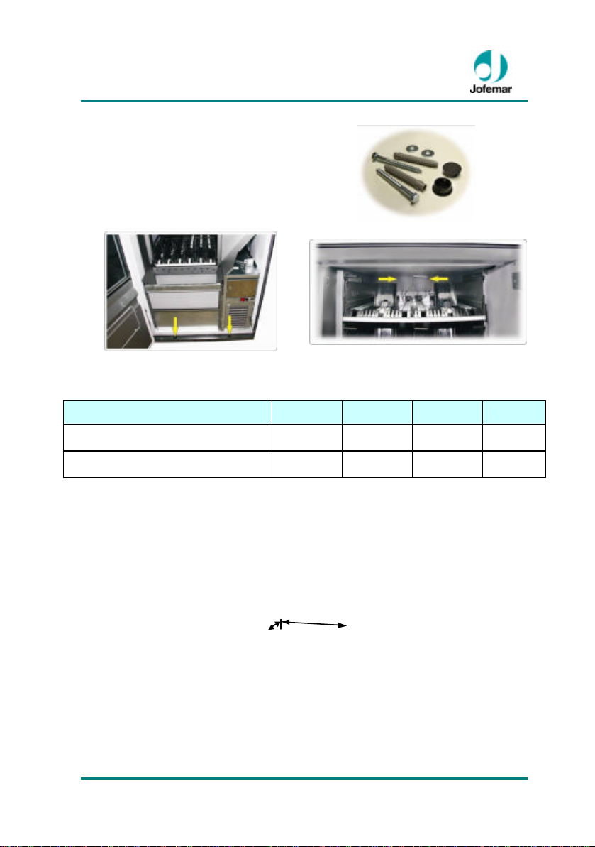
These machines are fitted with holes and
supplied with an anchoring kit (fig. 9) that
can be used to anchor the machine to the
floor (fig. 10) or to the wall (fig. 11) for
greater stability and support and to
prevent thefts.
Fig. 09
Fig. 10 Fig. 11
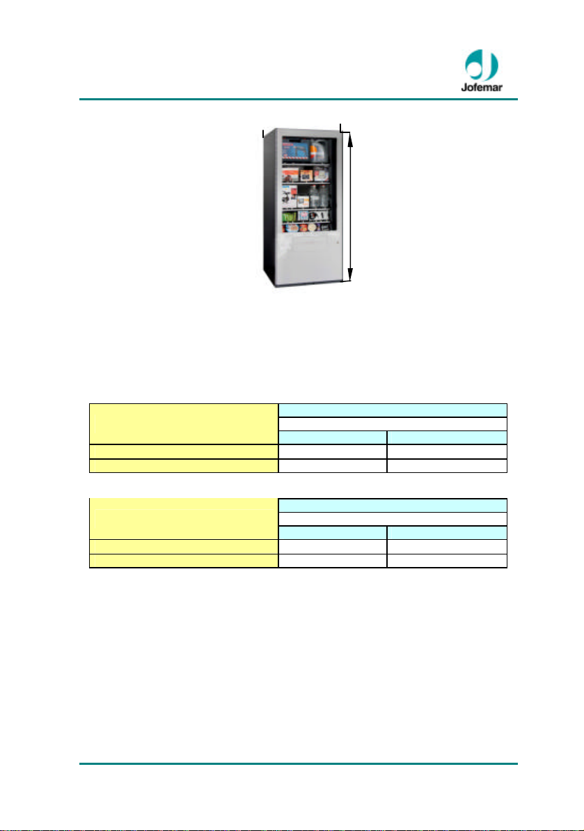
3.2. Volume and weight
Dimensions Height (H) Width (W) Depth (D) Weight
Vision Es-Plus (with cooling unit )
Vision Es-Plus (without cooling unit)
* The weight of the machine is for with a 5 tray configuration.
1.825 mm
(71.850”)
1.825 mm
(71.850”)
F
800 mm
(31.496”)
800 mm
(31.496”)
1010 mm
(39.763”)
975 mm
(39.763”)
306 Kg
671 lb
726 Kg
1597.2 lb
MNP141GBV00 Date: 2011/04/29 Rev. 0 PAGE 11 OF 24
Page 12
Vision Es-Plus // Vending
H
Vision Es-Plus
Fig. 12
4. Electric-electronic specifications ~
The cooling assembly, LED lighting power supply, turbine and transformer are supplied
with the mains voltage for the particular country where the machine is sold. They should
therefore not be handled without disconnecting the machine from mains.
Power supply voltage
vision
Es-Plus (without cooling unit) 100 W 0,4 A
Es-Plus (with cooling unit) 830 W 3,5 A
Maximum power Maximum intensity
vision
Es-Plus (without cooling unit) 100 W 0,4 A
Es-Plus (with cooling unit) 830 W 3,5 A
Maximum power Maximum intensity
230 ± 10% VAC. 50 Hz
Power supply voltage
110 ± 10% VAC. 60 Hz
4.1. Initial electrical installation ~
Prepare a socket, protected with an automatic connection system. The socket should
match the machine plug (European, with ground connection). Follow all Low Voltage
Installation Regulations and check that ground connection works properly once the
machine has been installed.
MNP141GBV00 Date: 2011/04/29 Rev. 0 PAGE 12 OF 24
Page 13
Vision Es-Plus // Vending
A B C D E
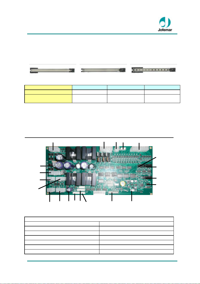
4.2. Product dispenser channel
There are three types of different product dispensers. Depending on the type of product
to be served, you can interchange these channels, offering a wide range of
combinations. A maximum of 10 dispenser channels can be added to each tray.
Motor power supply 12 Vcc 12 Vcc 12 Vcc
To properly dispense a product, the dispenser motor operation voltage has to be
programmed on the master machine to ensure the most appropriate dispensing speed
for each product.
Fig. 13 Fig. 14 Fig. 15
Ref. code 8210061 (Fig. 22) 8210062 (Fig. 23) 8210063 (Fig. 24)
Max. power
consumption
3 w 3 w 3 w
4.3. Control card
F
P G
Q
R H
I
S
O Ñ N T M L K J
CONNECTION CONTROL CARD
A. Transformer secondary and relays K. (Not in use)
B. Connection elevator L. Door microswitch connection
C. Connection tray motors M. RS-232 port connection (1)
D. (Not in use) N. RS-232 port connection (2)
E. Connection tray motors Ñ. (Not in use)
F. (Not in use) O. Set slave number
G. (Not in use) P. (Not in use)
Fig. 16
MNP141GBV00 Date: 2011/04/29 Rev. 0 PAGE 13 OF 24
Page 14
Vision Es-Plus // Vending
A
B
H. Thermometer connection Q. (Not in use)
I. (Not in use) R. Set slave number
J. Battery connection (temperature
controller)
T. Connection to master
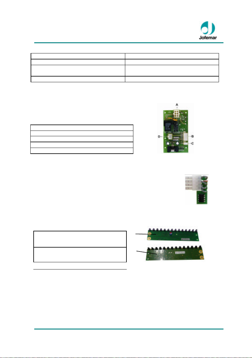
4.4. Relay card
RELAY CARD CONNECTORS
A. Cooling unit enabling and lighting
B. Control card power supply
C. (Not in use)
D. Transformer connection
Fig. 17
4.5. Electronic thermometer card
The temperature of the product hold is measured with an
electronic thermometer which can be placed in different
locations of the product hold. Normally, it is located half way up
the hold.
S. (Not in use)
Fig. 18
4.6. Elevator product detector photocell cards
A. Transmitting car
B. Detecting card
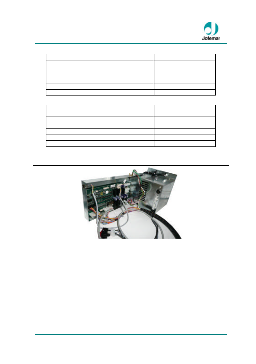
4.7. Electronic control system
The electronic control system is in the lower part of the cabinet. To access it you need to
previously remove the elevator product detector checking assembly.
In the case of refrigerated machines, you also have to remove the insulated cover that
protects the control card.
MNP141GBV00 Date: 2011/04/29 Rev. 0 PAGE 14 OF 24
Fig. 19
Page 15
Vision Es-Plus // Vending
POWER BOX VISION ES -PLUS 220 Vac
Main switch Bipolar
EMI filter 3 A.
Transformer power 100 W
Transformer primary 220 Vac
Transformer secondary 24 Vca , 15 Vca , 11Vca
220 Vac mains protection fuse 10 A.
POWER BOX VISION ES -PLUS 110 Vac
Main switch Bipolar
EMI filter 3 A.
Transformer power 80 W
Transformer primary 110 Vac
Transformer secondary 24 Vca , 15 Vca , 11Vca
110 Vac mains protection fuse 15 AT.
MNP141GBV00 Date: 2011/04/29 Rev. 0 PAGE 15 OF 24
Fig. 20
Page 16
Vision Es-Plus // Vending
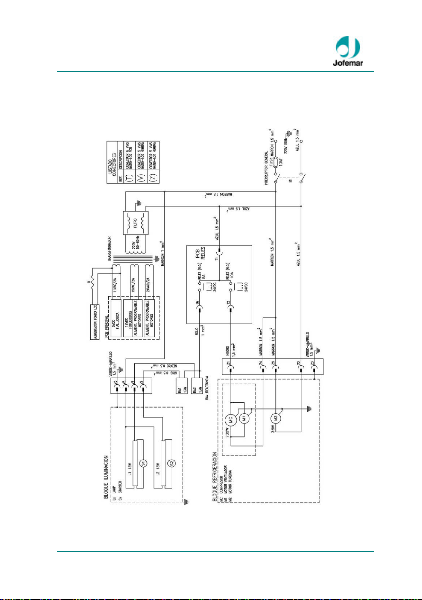
4.8. Machine electrical drawing
MNP141GBV00 Date: 2011/04/29 Rev. 0 PAGE 16 OF 24
Page 17
Vision Es-Plus // Vending
5. Installation and start up
5.1. Installation
Do not install the machine near active heat sources (heaters, radiators, etc.). Avoid
obstructing the grids located at the front of the cabinet to ensure air circulation inside,
where the cooling unit motor is located (if the machine has one). Leave a distance of at
least 7 centimetres between the back of machine and the wall or other items.
In 24 hour vending facilities, make sure that the hot air coming out of the machine at the
back can be easily discharged, i.e., that the machine is properly vented at the back.
Efficient removal of hot air significantly reduces the power consumption of your machine
and hence your electricity bill.
F IMPORTANT: It is important for the machine to be level, as it should operate in
a vertical position, both laterally and front-to back, placed so the mains plug is readily
accessible and with a maximum tilt of 5% (~2°) . This will also prevent noise and
vibration and will extend the cooling unit service life .
5.2. Start up
As a safety measure to avoid damaging the cooling circuit (if the machine has one), wait
to connect the machine to mains for 2 hours after finishing unpacking and installing the
machine.
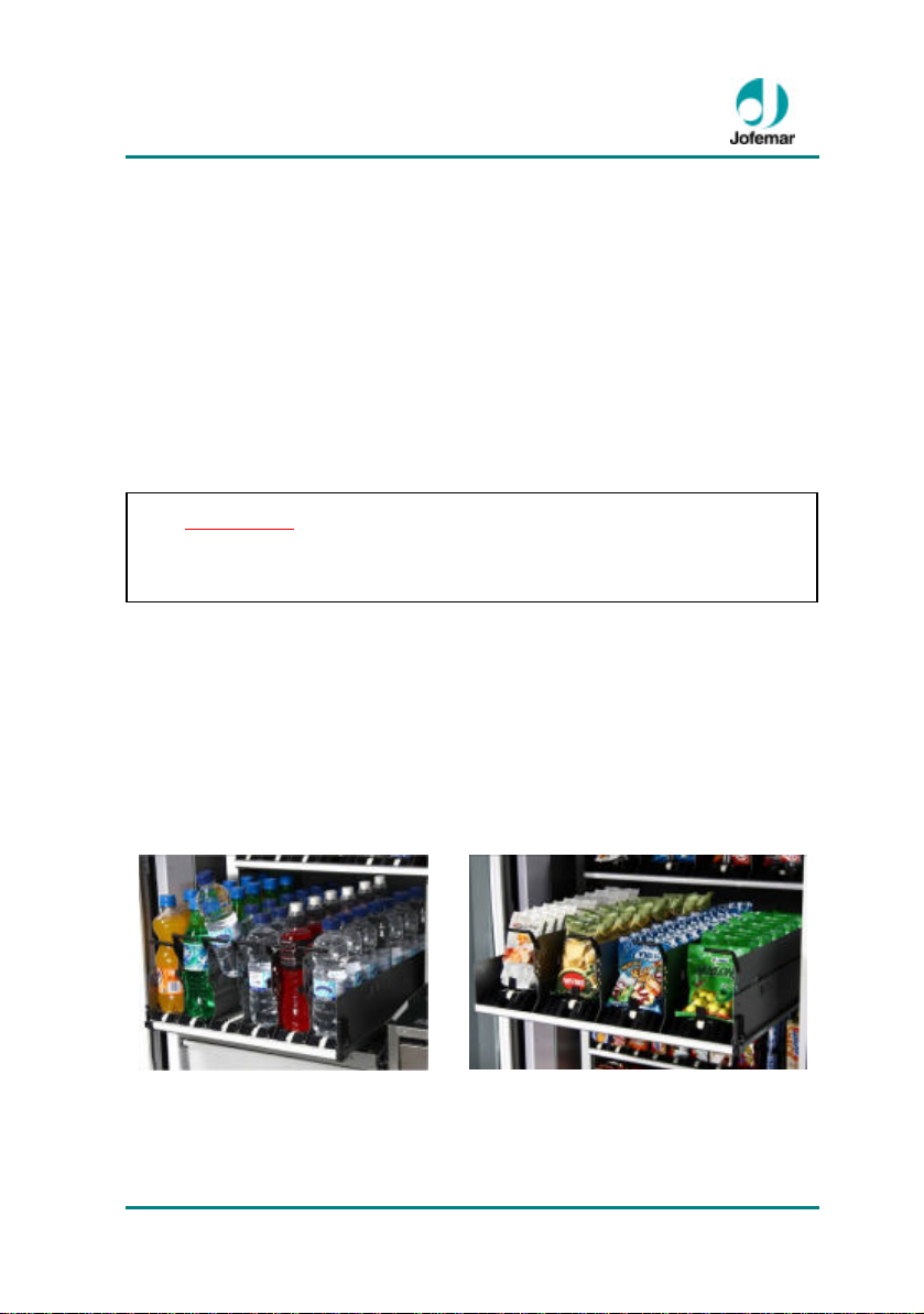
5.3. Restocking machine trays
Open the machine door, press the tray anchoring system (on the side), slide out the tray
to be restocked and place the products in their channel until all of the machine’s trays
have been restocked.
MNP141GBV00 Date: 2011/04/29 Rev. 0 PAGE 17 OF 24
Fig. 21
Page 18

Vision Es-Plus // Vending
5.4. Updating the machine program
The control card of the machine has been designed to use flash technology. This feature
allows you to update the card program. To perform this task you need to manually lift the
machine elevator until you can see the RS -232 connector. Program updating can be
done through a PC or an EasyFlash reprogramming device.
¦ USING A PC
Follow these steps to update the program:
1.- With the machine turned off, connect the PC to the machine using the RS-232 cable.
2.- Choose the program to install in flash memory:
• The program files should be stored in the subdirectory of the hard drive
corresponding to the VISION V3 machine.
• Run the PC program. Choose the menu option FLASH - RECORD - VISION V3
and choose the *.h00 file.
3.- Turn the machine on.
4.- When the program has been updated, a message will appear on the PC screen
indicating that the flash memory has been successfully recorded.
¦ i USING THE EASYFLASH REPROGRAMMING DEVICE
Follow these steps to update the program:
1.- With the machine turned off, connect the EASYFLASH device to the machine using
any of the cables supplied.
2.- As soon as the program is loaded, it will load the data from the file TYPES.DAT for
the machines with which you wish to communicate.
3.- The first thing the program requests is the type of operation you wish to carry out.
- Recording a program in flash memory.
- Erasing the card’s flash memory.
- Identifying the program recorded in a card.
4.- After choosing the operation, you have to select the machine with which you wish to
communicate.
5.- You need to select the file you are going to record.
-The program can work with two standard reference file formats, .HEX (Intel) and
.BIN. When the program has more than one bank, the file extensions will be .H00,
.H01, .H02 … (or .B00, .B01, .B02 …) and so on until all banks are completed. In
these cases, the program will only show the file of the first bank (.H00 or .B00).
-When you select a file, if the extension is .HEX or .BIN the program will know that
there is only one bank, while if it is .H00 or .B00 it will search for files with
consecutive extensions until it does not find any more (maximum .H09 or .B09) and
the number of files will be the number of banks recorded.
6.- After all the data has been recognised, the program will begin the operation chosen.
MNP141GBV00 Date: 2011/04/29 Rev. 0 PAGE 18 OF 24
Page 19
Vision Es-Plus // Vending
?
Check the fault in the
- This process is divided in two parts, the first is erasing the flash memory and the
second is the program recording.
7.- When the recording program has finished communicating with the machine, a new
window will appear showing the result of the process.
(For more information, consult the manual of the EASYFLASH reprogramming device)
6. Operation
For the correct operation of the ES-Plus slave machine, it must be connected to a
MASTER machine or to an external payment module with the appropriate software to
control this type of slave machine. Once the MASTER ma chine communicates with the
slave machine, the MASTER machine or MASTER module software will determine how
the slave machine is to function (extraction, self-tests, manual handling etc.).
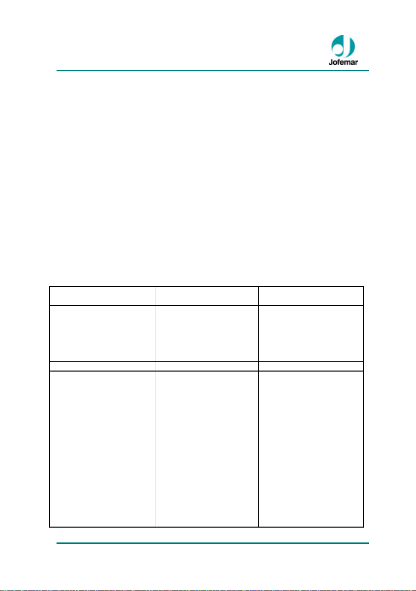
7. Troubleshooting
The following table will help you solve the most com mon machine failures. It describes a
series of anomalies, their possible causes and the steps to take in solving them or in
determining the cause of such failures before contacting our customer service.
? The MASTER machine or
M ASTER module does not
detect the slave machine.
? No sales are made from
any channel in the machine.
FAULT CAUSE SOLUTION
? Incorrect wiring
connection between them.
? Machine out of service
because of elevator break
down, product detection
system fault or because
there is no motor
connected.
? Check the connection
cable between the two
machines and the internal
connections of the cable
with the control card of the
slave machine.
MASTER machine
checking address.
? Should there be a fault in
the elevator due to a jam,
remove it and reset the
fault in the relevant address
of the MASTER machine.
? If the lift motor does not
move properly check if it is
getting power when you try
to move it via the manual
handling address of the
MASTER machine. If there
is no power supply, check
the wiring and control card.
Otherwise, replace the
MNP141GBV00 Date: 2011/04/29 Rev. 0 PAGE 19 OF 24
Page 20
Vision Es-Plus // Vending
? No sales from a channel
with product.
? Internal temperature is
not correctly regulated.
? Problems with the inside
door opening switch.
? Problems with the
electronic thermometer or
wiring.
? Problems with the
cooling unit.
motor.
? In case of fault in the
product detector, check
whether the product
detection LED indicator
product is always on. If it is,
you may have dirt in the
slots that the elevator has
to allow the infrared beam
through. Otherwise, place
an object inside the
elevator and check whether
the product detection LED
indicator turns on. If it does
not, there may be a faulty
transmitter or receiver card
or an incorrect card power
supply due to a defect in
the wiring.
? If no motor is connected,
check tray connections.
? Check that the inside
door opening switch works
properly, as otherwise, the
out of product marks will
not be erased.
? Check the MASTER
machine screen for the
relevant programming
option for the internal
temperature value to see
whether the thermometer
reading is correct. If not,
check the wiring. If there is
something with the wiring,
fix it or replace it and if it is
OK, replace the electronic
thermostat.
? Contact our technical
support service.
MNP141GBV00 Date: 2011/04/29 Rev. 0 PAGE 20 OF 24
Page 21
Vision Es-Plus // Vending
8. Annexes
8.1. Transport feet and adjustable levelling feet
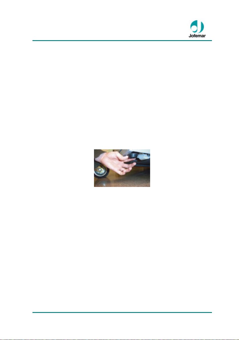
Once the machine is on the ground, it is advisable to remove the four (plastic) transport
feet for better stability, aided with the lifting jack as follows:
1º Raise the back, unscrew and remove the two plastic feet and let the machine rest on
the floor.
2º Open the machine door 90 degrees and raise the front end, unscrew the two plastic
feet and replace them with the two adjustable levelling feet, making sure that these are
fully screwed onto the base of the machine, and then roll the machine on its wheels to
the desired position.
3º Once the machine has been placed in its permanent position, raise the front again
with the lifting jack and level the door of the adjustable levelling feet (left and right see
fig. 22), with this system you can help to level the door perfectly, thereby preventing
scarping of he door.
Fig. 22
8.2. Cleaning and Maintenance
To ensure the machine works properly at all times, we recommend that the following
components be cleaned periodically:
? The outside glass should be cleaned periodically with a moist cloth or sponge and a
neutral product suitable for cleaning glass.
? The elevator should be cleaned whenever a product is spilled on it with a cloth
moistened with water and you should check that the moving parts are not obstructed.
? Whenever there is a spill in the product delivery bin, it should be cleaned with a cloth
moistened with water and all moving parts should be checked to ensure that they move
freely.
? If there is a spill on a tray, remove the tray from the machine and clean it using a cloth
moistened with water, never with alcohol or acids. Remove the channels from their slots
to better be able to clean the whole surface. Check that the belt moves freely and that it
MNP141GBV00 Date: 2011/04/29 Rev. 0 PAGE 21 OF 24
Page 22
Vision Es-Plus // Vending
is not obstructed anywhere along its path. Wait until it is completely dry before
reinstalling it.
? In general, keeping all internal areas that are visible to consumers clean increases
sales and improves the image of the machines.
? To access the lower trays (restocking area) open the machine’s exterior door and take
out the trays one at a time sliding them along their guides.
? There is a window on the back of the machine to allow air to circulate into it. This area
and the cooling unit condenser, which is just next to it, should be cleaned periodically
with a brush or compressed air to ensure it is not clogged with papers, bags or dust.
? The machine should never be cleaned with a water jet.
? The machine’s interior should always be dry to ensure it works properly.
? When handling the cooling unit, always do so with the machine turned off and make
sure that you do not bend any pipes, as they could break and produce a gas leak.
? It is very important never to touch any parts where there is LIVE VOLTAGE such as
the power box and the wiring supplying the LED lights. To access these areas, open the
m achine’s outside door and use a screw driver to remove the metal boxes protecting
these components.
? Access to servicing area should only be permitted to persons with a knowledge of and
practical experience in the machine, particularly with regard to health and safety.
? To clean the exterior of the machine, use a moist cloth with warm water and dry with a
soft cloth.
? In case of persistent stains (grease, drinks, etc.), do not apply abrasive products. Do
not use a cleaning spray! Use a solution of wate r and alcohol.
8.3. Recyclable
If you need to dispose of packaging materials consult your local authorities for recycling
information.
To manage the equipment as waste once the client has decided to dispose of it,
Jofemar has set up a collection system with an Integrated Management System
(ECOLEC). Please consult us for information about recycling.
MNP141GBV00 Date: 2011/04/29 Rev. 0 PAGE 22 OF 24
Do not throw away any electronic circuit as many of the materials that they
are made of are recyclable.
Page 23

Vision Es-Plus // Vending
8.4. Environment
Saving energy contributes to preserving the environment and, in the long run, helps save
a considerable amount of money. This section contains advice on optimising the
machine's use of energy as much as possible.
? The machine should be located in a cool, dry, well-ventilated place, so a location
meeting these requirements should be sought within the facilities.
? Avoid the machine’s direct exposure to sunlight. Use a parasol or sunshade if
necessary.
? Ensuring the cooling unit grilles are always clean and well ventilated will result in
significant energy savings and longer machine life.
? There is an option in the MASTER machine or MASTER module to control when the
machines lights go on and off. If you program the LED lighting to be on only during the
hours of less light, when visibility is low, the annual savings will be significant. In
locations with appropriate lighting, you can program the lights to be always off, in which
case the energy savings will be considerable.
? Open the machine door only when necessary and keep it open for as short a period as
possible. In locations without temperature regulation, product should be restocked during
the coolest time of the day.
The machine’s design process has been studied to ensure its has as little impact as
possible on the environment, both in the use of raw materials and in its assembly,
transport, service life and collection for recycling.
This section describes several material measures that show how Jofemar stands firm in
its commitment:
? Lower energy consumption.
? Wood being replaced with plastic feet.
? The entire box made of cardboard has been avoided.
? Improving the machine thermal isolation.
9. Regulation
The machines of the vision product range have been designed to European standards
as accredited by the CE mark on the machine data plate. Jofemar guarantees that these
machines meet applicable directives.
MNP141GBV00 Date: 2011/04/29 Rev. 0 PAGE 23 OF 24
Page 24

Vision Es-Plus // Vending
Jofemar S.A.
Reserves the right to introduce
improvements in this model arising from
its continuous research without prior
notice.
http:// www.jofemar.com
MNP141GBV00 Date: 2011/04/29 Rev. 0 PAGE 24 OF 24
 Loading...