

Page 1
User Manual
Joerns® Liing and Repositioning
HPL402 Hoyer® Power Patient Li
To avoid injury, read user’s manual before using.
Page 2

Joerns Liing and Repositioning
HPL402 Hoyer Power Patient Li
Table of Contents
Assembly ..................................................................................................................................................... 2
Specifications ............................................................................................................................................. 4
Troubleshooting Power Unit .................................................................................................................... 4
Operation .................................................................................................................................................... 5
Hoyer 4-Point Sling Information ............................................................................................................. 6
Lier Maintenance Checklist ................................................................................................................... 7
Warranty ...................................................................................................................................................... 8
This manual contains important safety and
maintenance instructions. Please read it carefully
before using your patient lier and refer to it as
oen as needed for safe and ecient use.
If you have any questions regarding the safe use
and/or assembly, maintenance or specifications of
your patient lier, you should call Joerns Healthcare
toll-free at 800.826.0270.
For service and repair, remember your authorized
Hoyer dealer is able to provide the assistance
you need. Save this manual for future reference.
For non-homecare liers, your maintenance
department should keep this manual.
Caution: For patient use, refer to the separate
manual, “How to Use a Patient Lier.” If you did not
receive a copy or need additional copies, contact
Joerns Healthcare at 800.826.0270.
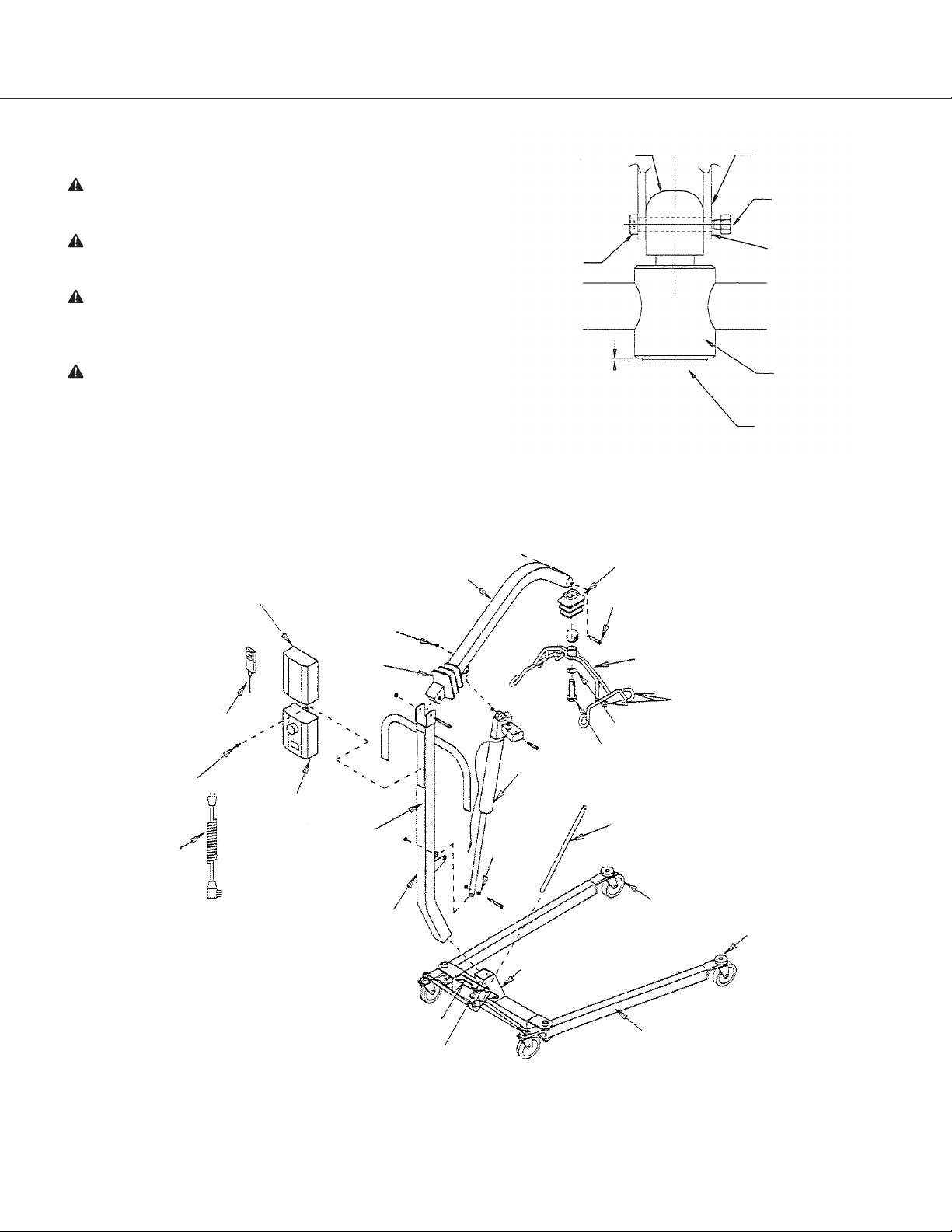
Assembly
For Installation of the HPL-P Power Conversion
Kit on Hoyer Liers
Recommended Tools: 3/4" and 1/2" wrench, 3/16"
hex wrench
Warning: All shoulder bolts must engage through
the bracket on both sides. If bolt is not fully
engaged, misalignment and premature failure may
result. Worn parts could fail, resulting in injury to
patient/caregiver (Figure 1, page 3).
Warning: The large thrust washer must be inserted
on the cradle hanger post (Figure 2). If washer is
not present, the cradle hanger post and cradle
center may wear prematurely. Warn cradle parts
could fail, resulting in injury to resident/caregiver.
Hanger post should protrude cradle center by
1/16th inch (Figure 1).
1. Carefully unpack lier in the following order:
a. Remove the outside top of the box.
b. Remove the three inside top fillers from the
box. NOTE: Be careful with the center filler, it
contains the electronics.
c. Remove base and adjustment handle from
the box.
d. Remove bottom filler from the box.
e. Remove cradle and mast assembly from
the box.
2. Apply a thin layer for grease to all bolts.
3. Place base of lier on a hard even surface with
the wheels contacting the surface. Insert the
mast in sleeve of base making sure that it is
fully engaged. Tighten the mask lock bolt
(Figure 2). Keep mast locked at all times except
while storing.
4. Place adjustment handle into socket as shown
(Figure 2). Pull adjustment handle back to unlock.
Handle can be moved to the right to widen the
base or to the le to narrow the base.
5. Remove boom from filler and attach to top of
mast with hardware as shown (Figure 2).
6. Remove actuator from filler and attach top of
actuator to mast and bottom to boom with
hardware (Figure 2).
7. Attach cradle to the end of boom with cap
and hardware (Figure 2). Pull vinyl boot over
connection, make sure middle rib is over
hardware.
8. Attach the power unit control box to bracket
on back of mast using 1/8" hex wrench. Attach
battery pack to control box and bracket. Route
actuator cable along mast and secure with clips
provided. (Make sure to leave approximately
8-inches of cable prior to the top clip, to allow
for maximum lifter articulation.) Plug cords in
proper outlets, pressing firmly into place (Figure
5.1)
9. Raise boom to highest position, pull vinyl boot
over bolted connection.
2
2
© 2015 Joerns Healthcare • 000-3558 RevD • 15-2003
Page 3
Joerns Liing and Repositioning
HPL402 Hoyer Power Patient Li
Lier Illustrations
Warning: Inside attachment points on cradle are
used for Hoyer slings with chains.
Warning: The four outside attachment points are
used for Partner-style slings.
Warning: Cradle Center Post must protrude below
the bottom of the Cradle Center Pivot Assembly
(approximately 1/16").
Warning: If Cradle center Post is flush or recessed,
excessive wear may have occurred. Worn cradle
parts could fail, resulting in serious injury or death to
patient and/or caregiver. Remove from service and
replace worn parts immediately.
Battery Pack
Lock Nut (4)
Boom
Friction Cap
Shoulder Bolt
1/16
Figure 1
Boot
Shoulder Bolt (4)
Bracket
ESN Nut
Shoulder Bolt, must
pass through bracket
Cradle
Cradle Hanger Post
Screw, Cntrol Box Mtg
Power Cord
Handset
Control Box
Boot
Wire Clips (2)
(Opposite Side)
Mast
Spreader Lock
Mast Lock Bolt
Figure 2
Cradle
Attachment Points
Thrust Washer
Hanger Post
Actuator
Adjustment Handle
Washer (4)
Caster (Wheel)
Bumper
Scuff Guard
3
© 2015 Joerns Healthcare • 000-3558 RevD • 15-2003
3
Page 4

Joerns Liing and Repositioning
HPL402 Hoyer Power Patient Li
Specifications
Maximum capacity: ....................................................................................................................................................... 400 lbs.
Lier weight ............................................................................................................................................ 93 lbs out of carton
Overall length .................................................................................................................................... 44 3/4 inches (114 cm)
Base clearance ............................................................................... 4 7/8 inces (12 cm) with three inch diameter wheels
Width of base, closed ......................................................................................... 24 inches (61 cm) without wheel swivel
Width of base, open ...................................................................................39 1/2 inches (100 cm) without wheel swivel
Length of base ............................................................................................... 43.6 inches (111 cm) without wheel swivel
Height of boom at lowest articulation .................................. 30 1/2 inches (77 cm) with three inch diameter wheels
Height of boom at highest articulation ..................................... 78 inches (198 cm) with three inch diameter wheels
Height of mast overall in base .............................................. 50 3/4 inches (129 cm) with three inch diameter wheels
Boom articulation radius ....................................................................................................................... 31.4 inches (80 cm)
Chair (20 inch wide) access .................................................................... 24 1/2 inches (CSP horizontal to center tube)
Beechwood powder coat finish
The following features are found on the Power Unit:
• Battery:2-12VRechargeableSealed •ChargerInput120VAC
• ChargerOutput24VDC •1SpeedOperation
• EmergencyDown •EmergencyMechanicaldown
• SoStop •EmergencyStop
• LCD Display for Battery Capacity Indication
• Acoustic battery alarm at about 50% battery capacity (0% LCD Display)
Troubleshooting, Power Unit
Symptom Possible Cause Action
Power indicator does
not light up
Power indicator lights up
but actuator does not
run. Relays in control box
are heard clicking.
Power indicator lights up
but actuator does not
run. No relay noise heard
from the control box.
Control box completely
dead on battery and no
relay clicking heard.
Actuator does not run
on battery, but relay
clicking heard.
Control box okay apart
from one direction on
one channel
• Not connected to mains
• The fuse has blown
• Control box defective
• Actuator plug not
pushed into control box
properly
• Actuator defective
• Control box defective
• Control box defective
• Handset defective
• Battery completely flat
• Battery defective
• Actuator plug not
pushed into control box
• Actuator defective
• Control box defective
• Handset defective
• Control box defective
• Connect to mains
• Replace fuse, if the system is prepared for external
fuse replacement or send the system for repair
• Send control box for repair
• Push actuator plug into control box properly.
• Replace actuator
• Replace the control box
• Send control box for repair
• Send handset for repair
• Charge battery
• Replace battery
• Push actuator plug properly into control box
• Replace actuator
• Replace control box
• Send handset for repair
• Send control box for repair
4
4
© 2015 Joerns Healthcare • 000-3558 RevD • 15-2003
Page 5

Joerns Liing and Repositioning
HPL402 Hoyer Power Patient Li
Operation
Hand Control
The hand control activates the lier and has two (2)
buttons; one “up” and one “down”.
Simply press the button for the direction you want
the lier to move.
Battery Charging
Plug the charger into the wall socket (110V)
prior to connecting the plug to the control box. A
control box with battery will hold a (unused) charge
for approximately six (6) months. To achieve the
longest life, keep the battery fully charged. Aer
approximately six (6) hours of charging, the batteries
will be fully charged and the LCD display should read
100%
Note: It is not possible to overcharge batteries.
Note: When battery alarm sounds, batteries should
be recharged.
Battery
1. Emergency Stop
2. Control Box
3. LCD-Display
Instructions
The duty cycle printed on the label of the control
box must always be noted. If the cycle has been
exceeded, the control box could overheat and
become damaged. Unless otherwise specified on
the label, the duty cycle is maximum 10% or
six (6) min/hour of continuous operation.
Emergency stop button should be pushed in when
not in use for an extended period of time, the LCD
Display will trickle down the battery.
Note: Power lier will not be operable during the
time the charger is connected.
Warning: Do not charge the battery while
someone is in the lier and especially if the unit is
being used in wet or bathing areas.
Caution: By unauthorized opening of the
system, there is a risk that it may malfunction
at a later date.
Warning: Liers can tip over. Keep base widened
for stability. Never lock brakes or block wheels
when liing someone. Brakes are provided for
parking. To lock casters, step on cam lever on side
of casters. To unlock brakes, step on highest
cam lever.
Hand Control Cord
Charging Cord
Actuator Cord
5
© 2015 Joerns Healthcare • 000-3558 RevD • 15-2003
5
Page 6

Joerns Liing and Repositioning
HPL402 Hoyer Power Patient Li
Hoyer 4-point Sling Information
Warning: Torn, cut, frayed or broken slings could
fail resulting in serious injury or death to patient.
Use slings in good condition only. Destroy and
discard old, unusable slings.
Note: Do not use any other manufacturer’s sling
with the HPL402 Lier.
Note: Do not use Hoyer slings with any other
manufacturer’s li.
Patient Size Guide
A B Weight
inch (cm) inch (cm) lbs (kg)
Large 28 (70) 19 (47) 198-400 (90-
191)
Medium 24 (61) 19 (47) 99-210 (45-95)
Small 18 (46) 15 (38) 55-110 (25-50)
*Patient’s weight to sling size information is an
approximation only.
Patient can be raised 4" higher by hooking up the
inside strap to the cradle.
Example of label found on back of Partner
Slings
6
6
© 2015 Joerns Healthcare • 000-3558 RevD • 15-2003
Page 7

Joerns Liing and Repositioning
HPL402 Hoyer Power Patient Li
Lier Maintenance Checklist
Only qualified persons should service and repair Hoyer liers. Regular maintenance of liers and accessories is
necessary to assure proper and safe operation. Read and observe the following recommended instructions.
Item Initially Before
each use
Base and Wheels
Base is even and level (all four wheels are on the floor)
Wheel bolts are tight
Wheels swivel and roll easily
Base Adjustment
Base locks securely, all parts are present
Base opens and closes smoothly
Check spreader lock and all hardware for wear
Mast
Mast fully engaged and locked into mast sleeve
Inspect for bends or deflections
Inspect all bolts and nuts for wear and tightness
Boom
Inspect all bolts and nuts for wear and tightness
Inspect to ensure the boom is centered between the base legs
Cradle
Check hanger post for wear or damage. Replace post if wear exceeds 1/16".
Check sling attachments for wear or deflection
Slings and Hardware
Check metal parts for wear or damage
Check all nuts, bolts and screws for wear and tightness
Check slings and web straps for wear or damage
Lubrication
Oil all pivot joints, including:
Top of mast where boom attaches
Top and bottom of actuator mounting
Pump handle hinge
Use a light grease to lubricate base adjustment lock plate and
all rotating hardware.
Wheel and swivel bearings
Cleaning*
Use mild soap to clean; dry thoroughly.
Apply auto or appliance wax
Keep painted surfaces clean from oil
✔ ✔
✔ ✔
✔ ✔
✔ ✔
✔ ✔
✔
✔ ✔
✔
✔
✔
✔ ✔
✔
✔
✔
✔
✔
✔
Bi-Monthly
✔
✔
✔
✔
✔
✔
✔
* Do not wash under water pressure.
7
© 2015 Joerns Healthcare • 000-3558 RevD • 15-2003
7
Page 8

Joerns Healthcare Warranty Program
for Hoyer HPL402 Power Patient Li
Your Hoyer Classics Lis are warranted for one
(1) year aer purchase by the original consumer/
owner.
Components are warranted as follows:
1. Lier structure; base, mast, boom, and
suspension cradle.
Parts
Hoyer Classics Lis contain various parts that
wear from normal use. These parts, such as rubber
parts, plastic parts and painted surfaces are not
covered under the one-year warranty but are
covered for 90 days aer date of purchase.
2. Hydraulic pump/jack (for manual liers).
3. Electronic control box, hand pendant, actuator
and battery (for power liers).
All other non-durable components, such as rubber
parts, plastic parts and painted surfaces, are
warranted for one (1) year from original consumer/
owner purchase. These non-durable components
are subject to normal wear and replacement.
Damage caused by use in unsuitable environmental
conditions or failure to maintain the product in
accordance with user and service instructions is
not covered. Any alteration, modification, or repair
unless performed by or authorized in writing by
Joerns Healthcare will void this warranty.
This warranty applies in the USA only. Check with
your supplier to find out if international warranties
apply.
Joerns Healthcare’s obligation under this warranty
is limited to supplying replacement parts, servicing,
or replacing, at its option, any product which is
found by Joerns Healthcare to be defective.
Warranty replacement parts are covered by the
terms of this warranty until the product’s original
warranty period expires.
When requested by Joerns Healthcare, parts
must be returned for inspection at the customer’s
expense. Credit will be issued only aer inspection.
Service
Most service requests can be handled by the
facility Maintenance Department with assistance
from the Joerns Healthcare Product Service
Department.
Should a technician be required, one will be
provided by Joerns Healthcare, at our discretion.
Only the Joerns Healthcare Product Service
Department can dispatch authorized technicians.
Post Acute, Acute, HomeCare
2430 Whitehall Park Dr. Ste 100
Charlotte, NC 28273
(P) 800.826.0270
(F) 800.457.8827
www.Joerns.com • www.RecoverCare.com email: info@joerns.com
VA/Government
19748 Dearborn Street
Chatsworth, CA 91311
(P) 800.966.6662
(F) 800.232.9796
This warranty is extended to the original purchaser
of the equipment.
Manufactured by:
Joerns Healthcare, LLC
2100 Design Rd. Ste 100
Arlington, TX 76014
Canadian Oce
1000 Clarke Rd. Ste 6
London, ON Canada N5V 3A9
(P) 866.546.1151
(F) 519.451.8662
United Kingdom and
Other Countries
+44 (0)844 811 1156
+44 (0)844 811 1157
© 2015 Joerns Healthcare • 000-3558 RevD • 15-2003
Netherlands
+31 (0)30 6363700
+31 (0)30 6363799
 Loading...