

Page 1
®
Hoyer
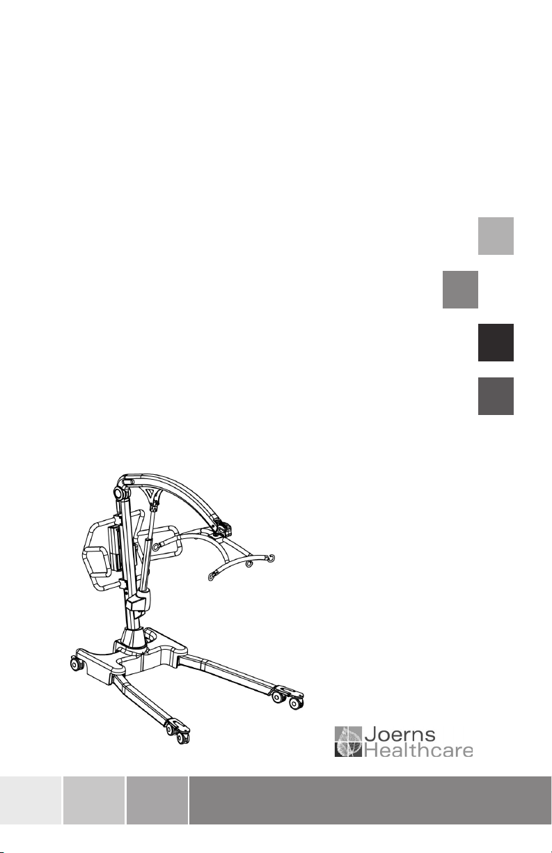
Hoyer® Calibre
User Instruction Manual & Warranty
To avoid injury, read user manual prior to use.
Hoyer® Calibre
Manuel de l’utilisateur et garantie
Afin d’éviter tout accident, veuillez lire attentivement la notice avant utilisation.
Hoyer® Calibre
Manual de Instrucciones y Garantia para el Usuario
Para evitar posibles daños, lea previamente el manual de usuario.
Hoyer® Calibre
Benutzerhandbuch und Garantie
Um Verletzungen zu vermeiden, lesen Sie bitte die Gebrauchsanweisung vor
der ersten Benutzung.
Redefining patient handling
Page 2

Hoyer
®
Calibre
Manufacturer’s Contact Details
®
Hoyer
USA
Joerns Healthcare Inc.
2100 Design Road
Suite 100, Arlington
TX 76014, USA
Tel: 800-826-0270
Fax: 800-457-8827
www.joerns.com
Contents
English
1. The Hoyer Calibre Patient Lift ........................................................................ 3
2. Introduction: About Your Lift ........................................................................... 4
3. Assembly and Commissioning Instructions .................................................... 5
4. Safety Precautions ......................................................................................... 9
5. Operating Instructions .................................................................................... 11
6. Removal of 6-point Cradle System................................................................. 15
7. Charging Instructions ...................................................................................... 17
8. Maintenance Schedule & Daily Check List .................................................... 19
9. Technical Specifications ................................................................................. 21
10. Warranty ......................................................................................................... 24
2
294000.10394 Rev. B
Page 3
English
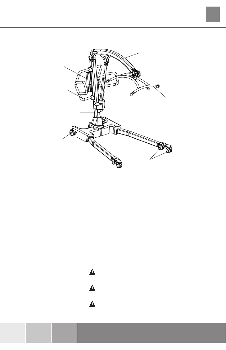
1. The Hoyer Calibre Patient Lift
Battery/
Control Pack
Push Handle
Electric Actuator
Mast
Rear Castor
(braked)
Front Castor
(non-braked)
Boom
Hoyer
Calibre
6-point Cradle
®
INTENDED USE:
The Hoyer Calibre lift is a passive patient handling device intended for the safe lifting and
transferring of patients up to a safe working load of 386 kg (850 lbs).
The Hoyer Calibre lift is intended for INDOOR USE ONLY and must to be operated by at least
two people/carers.
Advantages of the Hoyer Calibre lift include:
• Built in weigh-scale for easy monitoring of patient weight
• Safe working load of 386 kg (850 lbs)
• Extended push handle for two person operation to ease manoeuvrability when the lift is loaded
EXPECTED LIFETIME:
The expected lifetime of the Hoyer Calibre lift is five years (calculated from an average daily usage of
five lifts per day). This is based on the strict adhereance to the maintenance and servicing schedule
and daily checks as laid out in this user guide, and when performed by a competent engineer.
WARNING
Abusive use of the Hoyer Calibre lift will severely reduce the expected lifetime of the product.
WARNING
Servicing to be carried out by a competent service engineer only.
WARNING
A duty cycle of 7 minutes needs to be observed between uses. Failure to comply with the duty
cycle can result in significant reduction of product life expectancy.
294000.10394 Rev. B
3
Page 4

Hoyer
®
English
Calibre
2. Introduction: About Your Lift
The Hoyer Calibre is an electrically operated patient lift. Each Calibre lift is fully assembled load
tested and certified before being packed/shipped.
The packing consists of a strong, purpose built carton that is used for both export and domestic
markets to ensure the safe arrival of the lift.
A number of documents are supplied in a wallet, and packed with each lift and should be kept
safely for future reference.
• TEST CERTIFICATE • USER MANUAL
• DEALER GUARANTEE CARD • CUSTOMER SATISFACTION CARD
• PACKING CHECK LIST
The TEST CERTIFICATE is an important document and will be required for your insurance
records. It is valid for six months and after it has expired the lift should be inspected and serviced
per the maintenance schedule.
Servicing and periodic testing can be carried out by your authorised supplier. Please ensure your
lift is included in their maintenance schedule. If you are at all unsure what your local market servicing
requirements are, please check with your dealer and/or a local government agency.
The Hoyer Calibre is suitable for the following CATEGORIES of lift within the working parameters of
the lifts specified in the TECHNICAL SPECIFICATIONS.
Category A - Wheelchair
Category B - Bed
Category C - Bath (dependent upon setting)
Category D - Toilet/Shower Chair
Category E - Floor
Category F - 90 degree Rotation
The Hoyer Calibre is suitable for patients in the SITTING, SITTING/RECUMBENT and
RECUMBENT positions. The examples of slings suitable for use with this device are listed as follows:
• Hoyer Quickfit Bariatric (Safe working load - 385kg (850lbs)
• Hoyer Full Back Bariatric (Safe working load - 385kg (850lbs)
The CE mark:
The Hoyer Calibre carries the CE mark and complies
with the following EC directives:
• Medical Device Directive (93/42/EEC)
• EMC Directive (89/336/EEC)
• Low Voltage Directive (73/23/EEC)
4
294000.10394 Rev. B
Page 5
English
Hoyer
Calibre
3. Assembly and Commissioning Instructions
CARTON CONTENTS
Place the carton in a clear working area and open carefully. The carton contains:
•
HOYER CALIBRE LIFT
•
HAND CONTROL
•
CHARGING LEAD
•
WALLET CONTAINING DOCUMENTS
•
BATTERY PACK
•
DESK TOP CHARGER/STAND
TOOLS REQUIRED
The following tools will be required for assembly:
•
13MM SOCKET • TORQUE WRENCH
WARNING
Assembly and commisioning must be carried out by a competent engineer from an authorised
Hoyer Service Agent/Dealer.
WARNING
A MINIMUM OF 2 PERSONS REQUIRED. The Hoyer Calibre is heavy and will need to be
lifted with care. You will need assistance to lift the Hoyer Calibre from the carton.
ASSEMBLY INSTRUCTIONS
Remove all the parts from the carton and place on the floor, taking care to protect the paint finish
from damage.
®
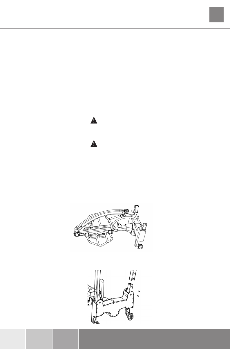
1. Place the mast/base assembly in a clear space and lay with rear castors and push handle on floor.
2. Fit the left and right hand legs (check correct orientation) onto the chassis using two M10
screws per leg as provided.
294000.10394 Rev. B
5
Page 6
Hoyer
®
English
Calibre
3. Tighten the M10 screws to secure each leg using a socket and torque wrench.
WARNING
Ensure the screws are secured firmly. It is recommended to tighten these to 10Nm
WARNING
Avoid trapping fingers. Keep fingers away from the end of the leg when inserting into the leg
socket. Keep fingers away from the front castor bracket during assembly of the legs to the base.
4. Lift the Calibre onto its castors.
NOTE: On a flat surface, all 6 castors must be in contact with the floor.
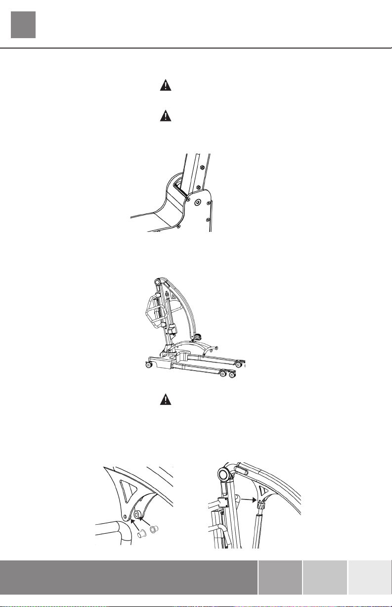
WARNING
The Calibre is extremely heavy, a minimum of 2 people will be required to lift the hoist.
5. Insert the two bushings into the outside of the mounting brackets on either side of the boom.
Lift the boom and position the actuator so that the upper fixing hole align with the mounting
bracket holes on the boom.
6
294000.10394 Rev. B
Page 7
English
Hoyer
Calibre
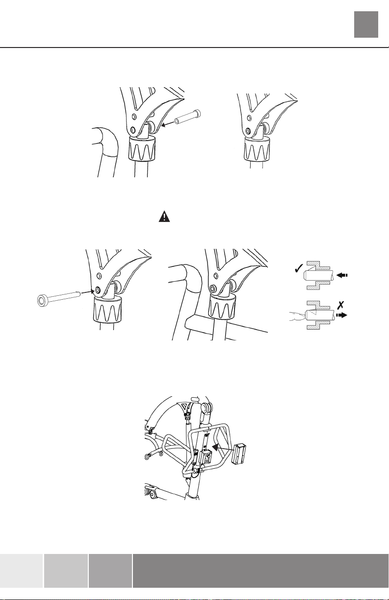
6. Insert quick-release pin sleeve into mounting bracket/actuator hole. make sure the
sleeve is fully engaged in the hole on both mounting brackets.
7. Insert the quick-release pin through the quick-release pin sleeve until it is fully located.
WARNING
Check that the quick-release pin has been fully inserted by trying to push the pin back out.
®
8. Fit power pack to the lift and make sure the latch holding the pack in place is fully
engaged. “Click” in place. Check that the battery is fully charged.
9. Plug the handset into the control box.
7
294000.10394 Rev. B
Page 8
Hoyer
®
English
Calibre
DISASSEMBLY
WARNING
Disassembly must be carried out by a competent engineer from an authorised Hoyer Service
Agent/Dealer.
The lift should not be disassembled unless for service, repair or transport if necessary. Therefore
follow the assembly instructions in reverse sequence.
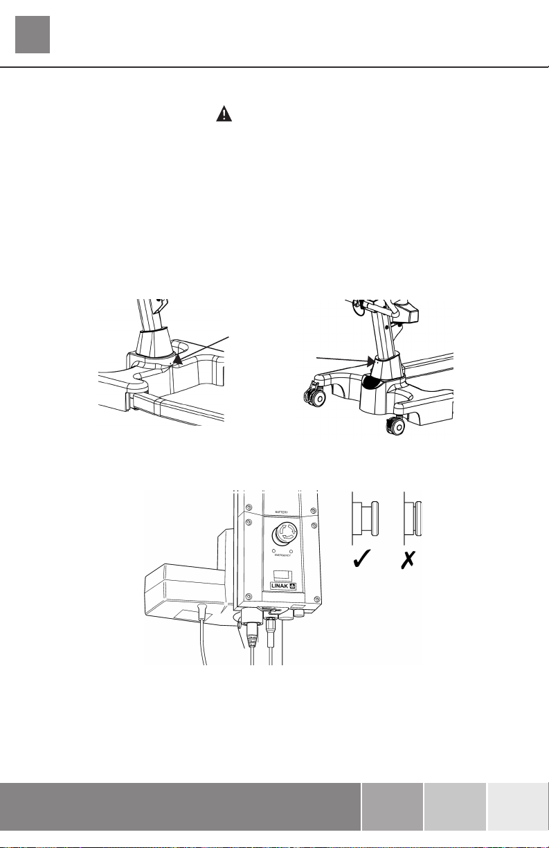
ALWAYS CHECK THE FOLLOWING BEFORE OPERATION
• The mast is fully locked into position by checking the grub screws at the front and rear of the
base are tight.
Front grub screw
Rear grub screw
• The red emergency stop button, located on the rear of the control box, is in the OFF (out) position.
8
294000.10394 Rev. B
Page 9

English
• The legs of the lift open and close satisfactorily (This is done via the hand control).
• Push the up and down buttons on the hand control and confirm the boom rises and lowers.
Hoyer
Calibre
®
294000.10394 Rev. B
9
Page 10

Hoyer
®
English
Calibre
4. Safety Precautions
Please read and follow the safety precautions listed below. The operation and use of Hoyer
patient lifts is simple and straight-forward. Following these few basic safety precautions will make
lifting operations easy and trouble free.
READ AND UNDERSTAND THE USER INSTRUCTION MANUAL BEFORE USING
YOUR “CALIBRE”
WARNING
• ALWAYS plan your lifting operations before commencing.
• ALWAYS carry out the DAILY CHECK LIST before using the lift.
• ALWAYS familiarise yourself with the operating control and safety features of a lift before
lifting a patient.
• DO NOT use a sling unless it is recommended for use with the lift.
• ALWAYS check the sling is suitable for the particular patient and is of the correct size
and capacity.
• NEVER use a sling which is frayed or damaged.
• ALWAYS fit the sling according to the instructions provided (user instructions).
• ALWAYS check the safe working load of the lift is suitable for the weight of the patient.
• ALWAYS carry out lifting operations according to the instructions in the user manual.
• NEVER disconnect or bypass a control or safety feature because it seems easier to operate
the lift.
• DO NOT lift a patient with the castor brakes on. Always let the lift find the correct centre of
gravity.
• DO NOT attempt to manoeuvre the lift by pushing on the mast, boom or patient.
• ALWAYS manoeuvre the lift with the handle / foot push pad provided.
• ALWAYS lower the patient to the lowest comfortable position before transfers.
• DO NOT push a loaded lift at speeds which exceed a slow walking pace (3 Km/hour 0.8
metres/second).
• DO NOT push the lift over uneven or rough ground. Particularly if loaded.
• DO NOT attempt to push/pull a loaded lift over a floor obstruction.
• NEVER force an operating/safety control. All controls are easy to use and do not
require excessive force.
10
294000.10394 Rev. B
Page 11

English
Hoyer
Calibre
• ALWAYS observe the duty cycle of 7 minutes between lifts. Failure to comply with the
duty cycle can result in significant reduction of product life expectancy.
• DO NOT park a loaded lift on ANY sloping surface.
• DO NOT use electric lifts in a shower.
• DO NOT charge an electric lift in a bathroom or shower room.
• DO NOT operate the hoist unless you are trained and competent to do so.
• YOUR lift is for patient lifting. DO NOT use it, or allow it to be used, for any other purpose.
• DO NOT bump the lift down steps, loaded or unloaded.
• DO NOT attempt to negotiate a loaded lift on a slope which exceeds 1:12 (approximately 5
degrees).
• DO NOT attempt to negotiate a slope unless a minimum of two persons/carers are present
for assistance.
• DO NOT use in a wet or corrosive environment such as poolside locations.
• DO NOT attempt to operate the hoist, loaded or otherwise unless a minimum of two
persons/carers are present for assistance.
®
294000.10394 Rev. B
11
Page 12

Hoyer
®
English
Calibre
5. Operating Instructions
OPERATING CONTROLS
Emergency Stop Button
Detachable
Battery Pack
Emergency
Lower/Raise
1. Leg adjustment
The legs on the Hoyer Calibre are electrically adjustable for width. The legs can be opened to
enable access around armchairs or wheelchairs. For transferring and negotiating narrow doorways
and passages the lift legs should be in the closed position.
Hand Control
Battery Indicator
Electric leg adjustment - is achieved by pressing the appropriate buttons on the handcontrol. The
legs will be locked whenever the handcontrol switch is released.
2. Castors and Braking
The lift has two braked castors which can be applied for parking. When lifting, the castors should
be left free and un-braked. The lift will then be able to move to the centre of gravity of the lift. If
the brakes are applied it is the patient that will swing to the centre of gravity and this may prove
disconcerting and uncomfortable.
3. Raising and lowering the boom
The movement of the boom is achieved by a powerful electric actuator which is controlled by a
simple hand control unit. The hand control has two buttons with directional arrows UP and DOWN
áâ. The actuator stops automatically at the limit of travel in both directions. The hand control
plugs into a socket at the base of the control box.
4. Emergency Stop
The red Emergency Stop Button is located on the front of the control box and is activated by
pressing in. This will cut all power to the lift and only be reset by twisting the button anticlockwise
and releasing.
12
294000.10394 Rev. B
Page 13

English
Hoyer
Calibre
5. Electrical Emergency Down/Up
Emergency lower (down) and raise (up) buttons are provided at the front of the control box. This
is operated by inserting a ballpoint pen into the button highlighted áâ. This will bring the boom
up or down should the handcontrol fail at any time.
6. Mechanical Emergency Down
In the case of a complete electrical failure the electrical actuator is fitted with a spring loaded
mechanical lowering device (RED BOSS). This will only operate when the lift is under load. The
device must twisted by hand and released to activate. A slow decent will commence. Repeat this
process until the patient has been safely lowered.
®
WARNING
If this feature is used, the lift MUST be subsequently checked out by a competent engineer.
7. Batteries
The batteries are protected from deep discharge by a LOW VOLTAGE ALARM. This will sound
when the batteries need recharging and the hand control is being operated. It will not sound
independently of the hand control being operated. DO NOT IGNORE THIS WARNING ALARM.
Complete the lifting operation and place the battery on charge (see charging instructions).
294000.10394 Rev. B
13
Page 14

Hoyer
®
English
Calibre
8. Slings
The Hoyer Calibre has a 6-point cradle.
The 6-point system uses slings with webbing loops, which allow positioning adjustment by selecting
different coloured loops.
Loop strap slings: Quickfit (Bariatric), Full Back (Bariatric) (SWL = 385kg/850lbs)
The 6-point system attaches to the 6-point cradle hooks via loop straps (shown below), each sling
is supplied with instructions. Please study the instruction guide before use.
Shoulder Straps
Attachment
Points
Attachment
Points
Leg Straps
6-point cradle. Example of 6-point cradle sling with loop attachments.
NOTE: For detailed fitting instructions, please refer to the user guide supplied with each sling.
WARNING
Joerns Healthcare recommends that slings be checked regularly and particularly before
use for signs of fraying or damage. DO NOT use slings that are worn or damaged.
WARNING
HOYER RECOMMENDS THE USE OF GENUINE HOYER PARTS. Hoyer slings and lifters
are not designed to be interchangeable with other manufacturer’s products. Using other
manufacturer’s products on Hoyer products is potentially unsafe and could result in
serious injury to patient and/or caregiver.
WARNING
Refer to maximum weight capacity of lift. Sling capacity is limited by the maximum
capacity of the lift.
14
294000.10394 Rev. B
Page 15

English
Hoyer
Calibre
6. Removal of 6-point Cradle System
FOLLOW THESE INSTRUCTIONS EXACTLY
Your Calibre lift uses the 6-point cradle. The removal of this systems is completed by the use of a
quick-release pin. This is done quickly and easily, but you must read the following safety instructions
to ensure the 6-point cradle is safely locked into position before use.
CONNECTION
WARNING
Two persons are required to fit the 6-point cradle OR a support table can be used.
To connect, raise the 6-point cradle up toward the boom slot.
Insert the pin sleeve through the plastic end cap to support the 6-point cradle.
Once aligned in the boom slot, reinsert the quick-release pin fully into the sleeve until it locks into
position. YOU MUST CHECK THAT THE PIN IS SECURELY FITTED.
To do this, press your finger into the barbed end. If the pin remains stationary the lift is safe to use.
®
294000.10394 Rev. B
15
Page 16

Hoyer
®
English
Calibre
REMOVAL
CAUTION: Be sure to support the weight of the 6-point cradle before removing pin.
To detach pin, depress the spring barb (using a flat blade electrical screw driver or similar) and
pull the pin out.
Support the 6-point cradle, and then pull the pin sleeve in the opposite direction, removing it
completely from the boom. This will release the 6-point cradle completely.
16
294000.10394 Rev. B
Page 17

English
Hoyer
Calibre
7. Charging Instructions
The batteries are located in the power pack and are charged via an off board desktop charger unit.
Removable Battery Pack
Hand Control
Legs Open/Close,
Boom Raise/Lower
Control Box
Emergency Stop, Raise/Lower
CHARGING INSTRUCTIONS FOR THE HOYER CALIBRE
When the power pack needs charging it is removed from the lift and fitted to an off board
charging unit.
Joerns Healthcare recommend an additional battery pack is purchased, so that one pack can be
on charge at all times.
®
1. Remove the power pack from the lift. The pack is retained by a simple latch at the top of the
power pack. Lift the latch and the power pack will be released.
2. Fit the power pack to the charging unit. The location and latching of the power pack to the
charger is the same system as used on the lift.
3. Plug the charger mains plug into a suitable mains outlet and switch the mains supply ON.
4. Charging is automatic and will fully charge the batteries over a period of eight to twelve hours.
Note: Even if the charger is left plugged in for extended periods it will not allow the batteries
to overcharge.
a) Green Light - Indicates main power is on.
b) Yellow Light - Indicates battery is charging.
c) Battery will be fully charged when yellow light goes off.
Note: Charging will take up to four (4) hours.
It is recommended that the battery be charged immediately upon receipt.
5. To return the lift to service, switch OFF the mains supply and remove the power pack from the
charger. Fit the power pack to the lift and make sure the latch holding the pack in place is fully
engaged. “Click” in place. The charging of Hoyer electric lifts is simple and straightforward, but
it is important to follow the charging instructions closely. Please pay particular attention to the
following points, they will help you avoid problems with discharged batteries.
294000.10394 Rev. B
17
Page 18

Hoyer
®
English
Calibre
WARNING
KEEP the batteries fully charged. Place the battery on charge whenever it is not in use. If
it is more convenient to do so, place on charge every night. The charger will not allow the
batteries to overcharge.
WARNING
NEVER run the batteries completely flat. As soon as the audible warning sounds, complete
the lifting operation in hand and place on charge.
WARNING
NEVER store the power pack for long periods without regular charging throughout the
storage period.
WARNING
ALWAYS make sure the mains power to the charger is switched off before connecting or
disconnecting the power pack.
WARNING
NEVER leave the power pack plugged in to the charger with the mains power off.
WARNING
Do not charge a battery in a bathroom or shower room.
18
294000.10394 Rev. B
Page 19

English
Hoyer
Calibre
8. Maintenance Schedule & Daily Check List
All Hoyer products are designed for minimum maintenance, however some safety checks and
procedures are required. A schedule of DAILY tasks are detailed below. Daily checks and a six
monthly service, inspection and test will ensure a lift is kept in optimum safe working condition. A
list of spare parts is available upon request.
The LOAD TEST and certification should only be carried out by qualified personnel or an authorised
service agent / dealer.
DAILY CHECK LIST: Joerns Healthcare strongly recommends the following checks be carried out
on a daily basis and before using lift.
• MAKE sure the lift moves freely on its castors.
• MAKE sure the 6-point cradle is free to rotate and swing
• EXAMINE & CHECK that the 6-point cradle is firmly attached to the boom.
• EXAMINE the sling hooks/clips on the 6-point cradle for excessive wear.
• MAKE sure the legs open and close correctly.
• OPERATE the hand control to confirm the boom raises and lowers satisfactorily.
• CHECK the operation of the emergency stop button.
• EXAMINE slings for fraying or other damage. DO NOT use any sling if damaged or if the
sling shows signs of wear.
• CONFIRM the lift is not giving a low battery alarm when the hand control is operated. If the
alarm sounds, DO NOT use, and place on charge immediately.
• MAKE sure the actuator connection points are secure.
®
MAINTENANCE, INSPECTION AND TEST
Joerns Healthcare recommend a thorough inspection and test of the Hoyer Calibre lift and lifting accessories, slings, scales etc is carried out on a regular basis. Inspection frequency varies depending on
locality, so you must check with your dealer or local government agency as appropriate regarding
how often an inspection is required. The examination and test should be conducted according to
the recommendations and procedures provided in this manual. Joerns Healthcare recommends
maintenance, inspection and certified testing is carried out by authorised service agent / dealers only.
NOTE: These recommendations are in compliance with the requirements of 1998 No2307 Health and Safety:
The Lifting Operations and Lifting Equipment Regulations 1998. This is a UK regulation. Outside the
UK please check your local country requirement
294000.10394 Rev. B
19
Page 20

Hoyer
®
English
Calibre
THESE CHECKS SHOULD INCLUDE:
Before Use
Initially
1. 6-POINT CRADLE: Check the 6-point cradle for freedom of rotation and
swing. Check for wear on the central pivot. Check for firm attachment to
the boom.
2. BOOM: Check the attachment of the boom to the mast. Make sure there
is only minimal side movement of the boom and the boom is free to rotate
on the boom bearing. Also check upper actuator fixings are secure.
3. MAST: Check the operation of the mast-locking screws. Make sure the mast
is fully engaged into the base socket. Check the bottom actuator fixings.
4. ACTUATOR: The actuator should require no maintenance other than
checking for correct operation and listening for unusual noise.
5. POWER PACK: Check the function of the emergency stop button and
emergency down/up.
6. BATTERIES: The batteries are housed in the power pack and should not
require maintenance other than the regular charging as detailed in the
charging instructions. Check that the connections remain clean.
7. LEG ADJUSTMENT: Check the legs operate in both full extensions
(inward/outward).
8. CASTORS: Check all castors for firm attachment to the legs. Check for free
rotation of the castors and the wheels.
9. CLEANING: Clean with ordinary soap and water and/or any hard surface
disinfectant. Harsh chemical cleaners or abrasives should be avoided as
these may damage the surface finish of the lift. Avoid wetting any of the
electrical parts.
10. LOAD TEST: The load test should be carried out in accordance with the
manufacturer’s test procedures. It is strongly recommended the testing is
carried out by an authorised service dealer.
11. BASE AND WHEELS: Ensure base is even and level
(all four wheels are on the floor).
12. SLINGS: Check for wear and fraying.
13. LUBRICATION: Oil pivot joints, including mast and boom connections, pedal ü
assembly and 6-point cradle joint (only if required).
14. HAND SET: Ensure plugged fully into controller.
15. QUICK RELEASE PIN: Ensure the pin is securely fitted before lifting, by ü
pressing the barbed end on the actuator and 6-point cradle
16. FIXINGS: Check all nuts, bolts, screws and fasteners for excessive wear
and for tightness. Replace as required.
ü ü ü
ü ü ü
üü ü
ü ü ü
üü ü
üü ü
ü ü
ü ü ü
ü ü ü
ü ü ü
ü ü
Service
Intervals
ü
ü
ü
ü
20
294000.10394 Rev. B
Page 21

English
9. Technical Specifications
Safe Working Load .........................................................850 lbs 385 kgs
Maximum Overall Length ................................................64 inches 1625 mm
Minimum Overall Length .................................................67 inches 1700 mm
Maximum Overall Height .................................................88.5 inches 2250 mm
Minimum Overall Height ..................................................62.5 inches 1590 mm
6-point Cradle Maximum Height .....................................76 inches 1930 mm
6-point Cradle Minimum Height .......................................29.8 inches 755 mm
Height at Maximum Reach ..............................................67.5 inches 1710 mm
Reach at Maximum Height ..............................................28 inches 710 mm
Reach at Minimum Height ...............................................26 inches 660 mm
Maximum Reach* ............................................................37 inches 940 mm
Turning Radius ................................................................76.5 inches 1940 mm
Legs Open- External Width ............................................55.3 inches 1400 mm
Legs Open- Internal Width ..............................................49 inches 1245 mm
Legs Closed- External Width ..........................................33.3 inches 845 mm
Legs Closed- Internal Width ...........................................26.8 inches 680 mm
Overall Height of Legs .....................................................4.8 inches 115 mm
Ground Clearance ...........................................................0.6 inches 15 mm
Front Twin Castors ..........................................................4 inches 100 mm
Rear Braked Castors .......................................................4 inches 100 mm
* Reach = centre of 6-point cradle to the front of the mast
Hoyer
Calibre
®
Weights
Mast, Base & Boom Assembly ........................................240 lbs 109 kgs
(includes 6-point cradle)
Power Pack .....................................................................6.6 lbs 3 kgs
Total .................................................................................246.6 lbs 112 kgs
6-point Cradle ..................................................................20 lbs 9 kgs
All measurements are nominal.
21
294000.10394 Rev. B
Page 22

Hoyer
®
Calibre
ELECTRICAL SPECIFICATIONS
BATTERIES .....................................................................24 volt Rechargeable sealed lead acid type
BATTERY CAPACITY .....................................................3.2 Ampere hours
CHARGER RATED INPUT .............................................230Vac 50/60Hz
CHARGER RATED OUTPUT .........................................27.4/29.0 VDC@0.8A
Electric Shock Protection
CHARGER .......................................................................CLASS II
LIFT .................................................................................INTERNAL POWER SOURCE
Degree of Shock Protection
CHARGER .......................................................................TYPE B
LIFT .................................................................................TYPE B
ENVIRONMENTAL CONDITIONS
Outside this environment functionality and safety may be compromised.
Operating
TEMPERATURE .............................................................>+5˚C <+40˚C
RELATIVE HUMIDITY .....................................................20% - 90% @ 30ºC (not condensing)
English
Storage
TEMPERATURE .............................................................>-10˚C <+50˚C
RELATIVE HUMIDITY .....................................................20% - 90% @ 30ºC (not condensing)
ATMOSPHERIC PRESSURE .........................................700 - 1060 hpa
IP Ratings
CONTROL BOX ..............................................................IPX4
ACTUATOR .....................................................................IPX6
OFF-BOARD CHARGER ................................................IPX5
BATTERY ........................................................................IPX5
HANDSET .......................................................................IPX5
Duty Cycles
ACTUATOR .....................................................................10% (2 mins / 18 mins)
CHARGER .......................................................................4 hours (approx.)
Acoustics
A-WEIGHTED SOUND POWER LEVEL.........................64dB
22
294000.10394 Rev. B
Page 23

English
Hoyer
Calibre
KEY SYMBOLS:
The following symbols are used on the charger, control unit and battery:
Type B equipment, as per EN 60601-1
Class 2 equipment
The disposal of the charging and control unit should not be mixed with general household
waste
®
The disposal of batteries should not be mixed with general household waste.
The disposal of electronics should not be mixed with general household waste
For indoor use
ATTENTION, consult accompanying documents.
WEEE Producers registration number WEE/GG0464RZ
23
294000.10394 Rev. B
Page 24

Hoyer
®
English
Calibre
10. Warranty
This warranty covers HoyerPro lifts only. Lifts not covered under this warranty include, but are not
limited to Advance-H, HML400, HPL600WB, HPL600WBSC, HPL402, C-HLA (and variations).
HoyerPro lifts are guaranteed for a period of two years from the date of delivery against defects in
materials and workmanship under normal use and service. This warranty includes all mechanical
and electrical components.
Aluminium structural components and mechanical components on lifts are covered under warranty
for a period of five (5) years from the date of delivery.
Damage caused by use in unsuitable environmental conditions or failure to maintain the product
in accordance with user and service instructions is not covered. Any alteration, modification or
repair unless performed by or authorized in writing by Joerns Healthcare will void this warranty.
Parts:
HoyerPro lifts contain various parts that wear from normal use. These parts, such as DC batteries
and casters are not covered under the two-year warranty but are covered for 90 days after date
of delivery.
Joerns Healthcare’s obligation under this warranty is limited to supplying replacement parts, servicing
or replacing, at its option, any product which is found by Joerns Healthcare to be defective.
Warranty replacement parts are covered by the terms of this warranty until the product’s original
warranty period expires.
When requested by Joerns Healthcare, parts must be returned for inspection at the customer’s
expense. Credit will be issued only after inspection.
Service:
Most service requests handled by the facility Maintenance Department with assistance from the
Joerns Healthcare Product Service Department.
Most parts requested can be shipped next day air at the customer’s expense.
Should a technician be required, one will be provided by Joerns Healthcare, at our discretion.
Only the Joerns Healthcare Product Service Department can dispatch authorized technicians.
This warranty is extended to the original purchaser of the equipment.
24
294000.10394 Rev. B
Page 25

English
Hoyer
Calibre
®
294000.10394 Rev. B
25
Page 26

Joerns Healthcare Inc.
2100 Design Road
Suite 100, Arlington
TX 76014
USA
Tel: 800-826-0270
Fax: 800-457-8827
www.joerns.com
© 2011, Joerns Healthcare
294000.10394 Rev B
DCO. XX-XXXX
 Loading...