

Joerns Healthcare 294000.10394-Hoyer-Calibre-A5-Rev-C-LR-ENGLISH2 Arcing grooves in commutator with a lathe
Page 1
User Instruction Manual
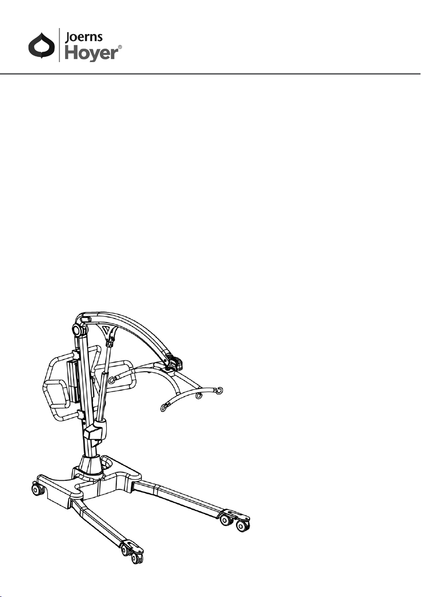
Hoyer® Calibre
To avoid injury, read user manual prior to use.
Manuel de l’utilisateur
Hoyer® Calibre
Afin d’éviter tout accident, veuillez lire
attentivement la notice avant utilisation.
Manual de Instrucciones
Hoyer® Calibre
Para evitar posibles daños, lea
previamente el manual de usuario.
Page 2

®
Hoyer
Calibre
Contents
1. The Hoyer Calibre Patient Lift ........................................................................... 3
2. Introduction: About Your Lift ............................................................................. 4
3. Assembly and Commissioning Instructions ...................................................... 5
4. Safety Precautions ............................................................................................ 10
5. Standard Control Box & Handset ...................................................................... 12
6. Smart Monitor & Handset .................................................................................. 13
7. Operating Instructions ....................................................................................... 17
8. Removal of 6-point Cradle System ................................................................... 19
9. Charging Instructions ........................................................................................ 21
10. Maintenance Schedule & Daily Check List ....................................................... 22
11. Technical Specifications .................................................................................... 24
12. Warranty ............................................................................................................ 27
English
2
Page 3
English
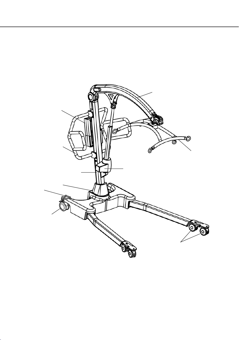
1. The Hoyer Calibre Patient Lift
Battery/
Control Pack
Push Handle
Boom
Hoyer
Calibre
6-point Cradle
®
Straight Line
Steering Device
Rear Castor
(braked)
Mast
Foot Push Pad
Electric Actuator
Front Castor
(non-braked)
3
Page 4

®
Hoyer
Calibre
2. Introduction: About Your Lift
Each Calibre lift is fully load tested and certified before being packed/shipped.
The packing consists of a strong, purpose built carton that is used for both export and domestic
markets to ensure the safe arrival of the lift. A number of documents are supplied in a wallet, and
packed with each lift and should be kept safely for future reference.
• TEST CERTIFICATE
• USER MANUAL
The TEST CERTIFICATE is an important document and will be required for your insurance
records. It is valid for six months and after it has expired the lift should be inspected and serviced
per the maintenance schedule.
To properly maintain your lift please refer to the maintenance schedule included in this document. If
you are at all unsure what your country’s servicing requirements are, please check with your dealer
and/or a local government agency.
Statement of Intended Use
The Hoyer Calibre lift is a passive patient handling device intended for the safe lifting and
transferring of patients up to a safe working load of 385 kg (850 lbs).
English
The Hoyer Calibre lift is intended for INDOOR USE ONLY and must be operated by a MINIMUM
of two people/carers.
The Hoyer Calibre is an electrically operated patient lift, designed to support and promote safe
patient handling and transfer for both the patient and carer.
The Hoyer Calibre is suitable for patients in the SITTING, SITTING/RECUMBENT and
RECUMBENT positions. The slings suitable for use with this device are listed as follows:
• Hoyer Bariatric Hammock Sling (Safe working load - 385kg / 850lbs)
Expected Service Life
Hoyer Professional lifts are designed and tested for a minimum service life of ten (10) years,
subject to the use and maintenance procedures stated in this manual. Use, other than in accordance
with these instructions, may compromise service life.
4
Page 5
English
3. Assembly and Commissioning Instructions
Carton Contents
Place the carton in a clear working area and open carefully. The carton contains:
•
HOYER CALIBRE LIFT
•
HAND CONTROL
•
CHARGING LEAD
Tools required
The following tools will be required for assembly:
•
13MM SOCKET • TORQUE WRENCH
Assembly and commissioning must be carried out by a competent engineer from an
authorised Hoyer Service Agent/Dealer.
A MINIMUM OF 2 PERSONS REQUIRED. The Hoyer Calibre is heavy and will need to be
lifted with care. You will need assistance to lift the Hoyer Calibre from the carton.
•
WALLET CONTAINING DOCUMENTS
•
BATTERY PACK
•
DESK TOP CHARGER/STAND
WARNING
WARNING
Hoyer
Calibre
®
Assembly Instructions
Remove all the parts from the carton and place on the floor, taking care to protect the paint finish
from damage.
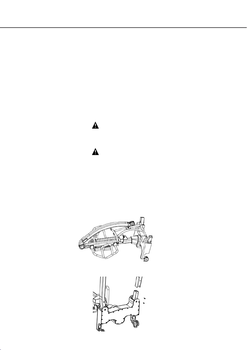
1. Place the mast/base assembly in a clear space and lay with rear castors and push handle on floor.
2. Fit the left and right hand legs (check correct orientation) onto the chassis using two M10
screws per leg as provided.
5
Page 6
®
Hoyer
Calibre
3. Tighten the M10 screws to secure each leg using a socket and torque wrench.
WARNING
Ensure the screws are secured firmly. It is recommended to tighten these to 10Nm
WARNING
Avoid trapping fingers. Keep fingers away from the end of the leg when inserting into the leg
socket. Keep fingers away from the front castor bracket during assembly of the legs to the base.
4. Lift the Calibre onto its castors.
NOTE: On a flat surface, all 6 castors must be in contact with the floor.
English
WARNING
The Calibre is extremely heavy, a minimum of 2 people will be required to lift the hoist.
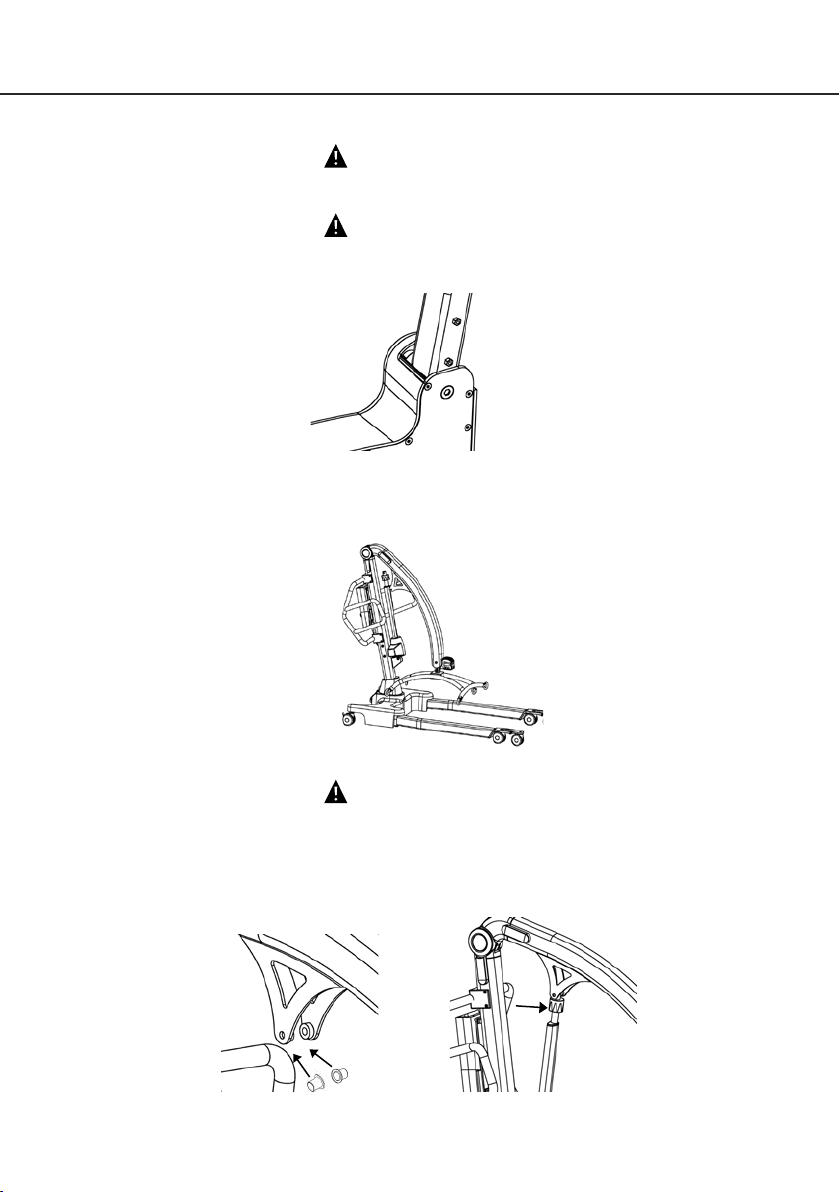
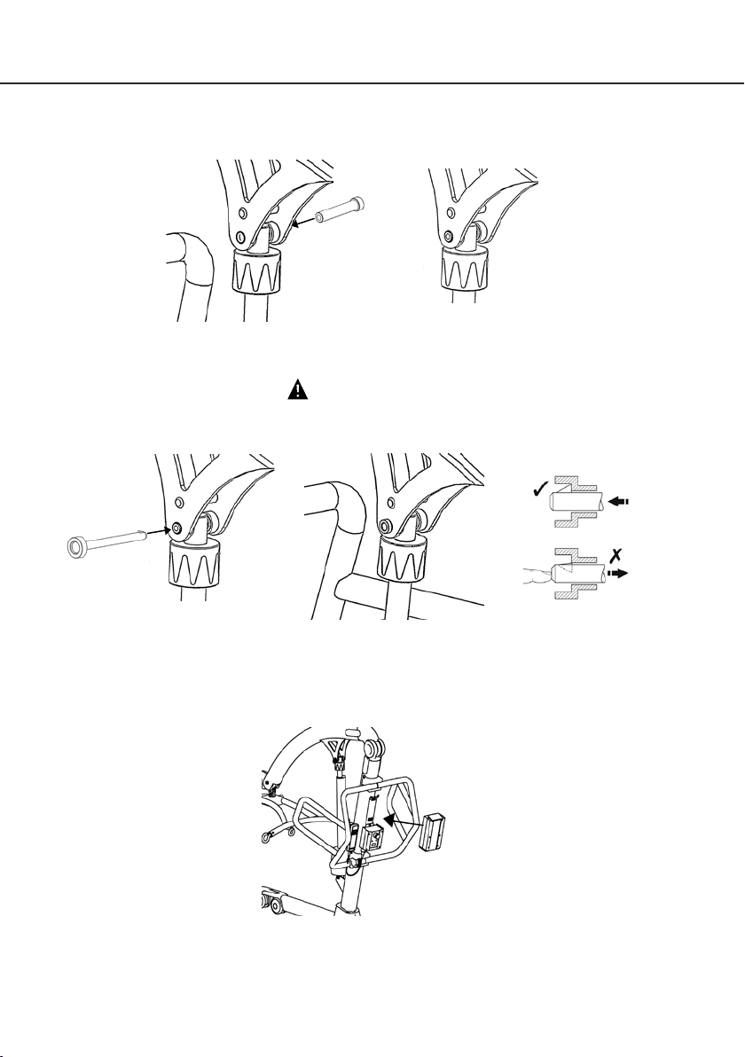
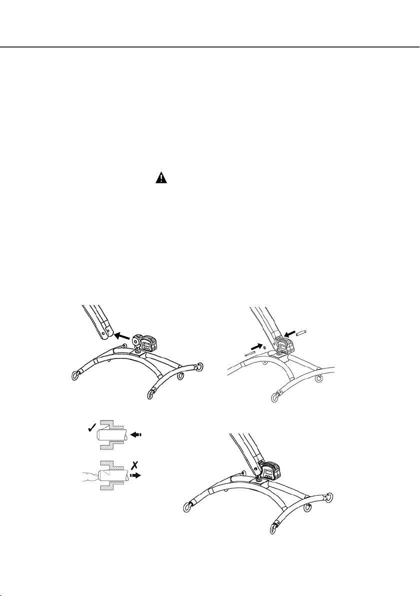
5. Insert the two bushings into the outside of the mounting brackets on either side of the boom.
Lift the boom and position the actuator so that the upper fixing hole align with the mounting
bracket holes on the boom.
6
Page 7
English
6. Insert quick-release pin sleeve into mounting bracket/actuator hole. make sure the sleeve is
fully engaged in the hole on both mounting brackets.
7. Insert the quick-release pin through the quick-release pin sleeve until it is fully located.
WARNING
Check that the quick-release pin has been fully inserted by trying to push the pin back out.
Hoyer
Calibre
®
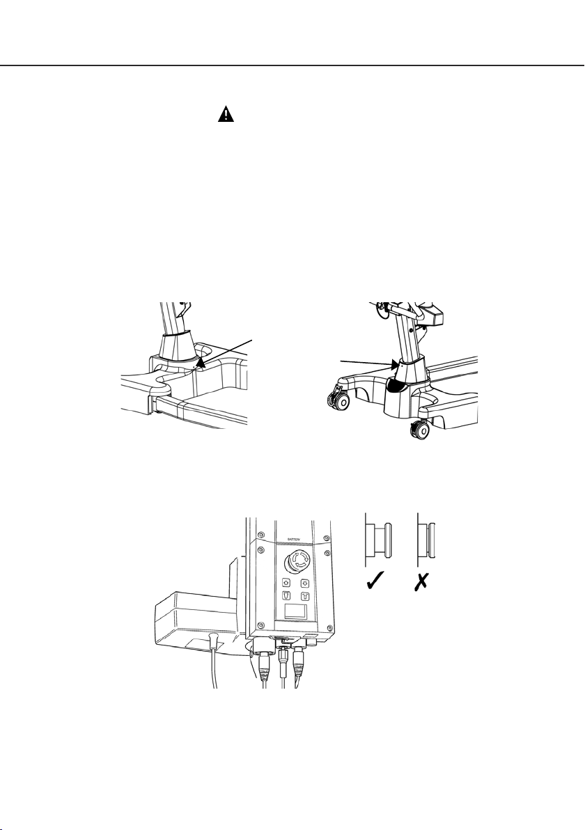
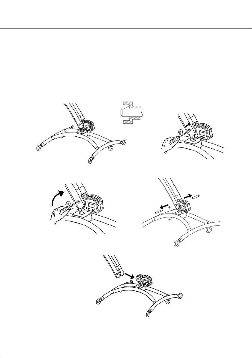
8. Fit power pack to the lift and make sure the latch holding the pack in place is fully engaged.
“Click” in place. Check that the battery is fully charged.
9. Plug the handset and actuator cables into the bottom of the controller. Refer to the figures on
page 12 or 13 for correct positions.
7
Page 8
®
Hoyer
Calibre
Disassembly
WARNING
Disassembly must be carried out by a competent engineer from an authorised Hoyer Service
Agent/Dealer.
The lift should not be disassembled unless for service, repair or transport if necessary. Therefore
follow the assembly instructions in reverse sequence.
ALWAYS CHECK THE FOLLOWING BEFORE OPERATION
• The mast is fully locked into position by checking the grub screws at the front and rear of the
base are tight.
Front grub screw
Rear grub
screw
English
• The red emergency stop button, located on the rear of the control box, is in the OFF (out)
position.
8
Page 9
English
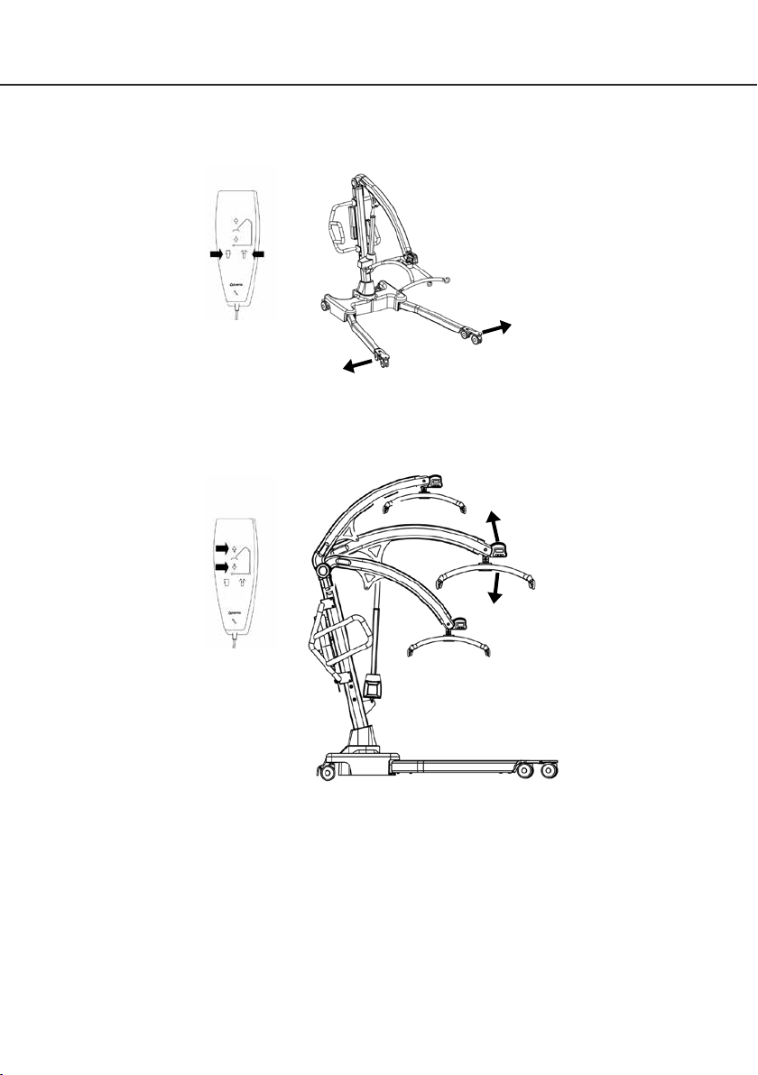
• The legs of the lift open and close satisfactorily (This is done via the hand control).
• Push the up and down buttons on the hand control and confirm the boom rises and lowers.
Hoyer
Calibre
®
9
Page 10

®
Hoyer
Calibre
4. Safety Precautions
Please read and follow the safety precautions listed below. The operation and use of Hoyer
patient lifts is simple and straight-forward. Following these few basic safety precautions will make
lifting operations easy and trouble free.
Please read and follow the safety precautions listed below. The operation and use of Hoyer
patient lifts is simple and straightforward. Following these few basic safety precautions will make
lifting operations easy and trouble free.
READ AND UNDERSTAND THE USER INSTRUCTION MANUAL BEFORE USING THE
HOYER CALIBRE LIFT
WARNING: Important safety information for hazards that might cause serious injury.
CAUTION: Information for preventing damage to the product.
NOTE: Information to which you should pay special attention.
WARNING
• DO NOT lift a patient unless you are trained and competent to do so.
• ALWAYS carry out the DAILY CHECK LIST located towards the end of the manual
before using the lift.
• DO NOT exceed the safe working load of the lift.
• ALWAYS plan your lifting operations before commencing.
• ALWAYS familiarize yourself with the operating control and safety features of a lift
before lifting a patient.
• DO NOT use a sling unless it is recommended for use with the lift.
• ALWAYS check the sling is suitable for the particular patient and is of the correct
size and capacity.
• NEVER use a sling, which is frayed or damaged.
• ALWAYS fit the sling according to the instructions provided (user instructions).
• ALWAYS check the safe working load of the lift is suitable for the weight of the
patient.
• ALWAYS carry out lifting operations according to the instructions in the user manual.
• NEVER disconnect or bypass a control or safety feature because it seems easier to
operate the lift.
• ALWAYS lock the wheels when lifting from the floor.
• DO NOT attempt to manoeuvre the lift by pushing on the mast, boom or patient.
• ALWAYS manoeuvre the lift with the handle provided. A foot push pad is also
provided.
English
10
Page 11

English
• DO NOT push a loaded lift at speeds, which exceed a slow walking pace (2.6 ft/sec).
• DO NOT push the lift over uneven or rough ground. Particularly if loaded.
• DO NOT attempt to push/pull a loaded lift over a floor obstruction.
• NEVER force an operating/safety control. All controls are easy to use and do not
require excessive force.
• DO NOT park a loaded lift on ANY sloping surface.
• DO NOT use electric lifts in a shower.
• DO NOT use or store a lift in a wet or corrosive environment such as shower, bath or
pool locations.
• DO NOT charge batteries in a bathroom or shower room.
• DO NOT place or store batteries under direct sunlight or near a heat source.
• YOUR lift is for patient lifting. DO NOT use it, or allow it to be used, for any other
purpose.
• DO NOT bump the lift down steps, loaded or unloaded.
• DO NOT attempt to negotiate a loaded lift on a slope, which exceeds 1:12
(approximately 5 degrees)
• DO NOT attempt to negotiate a slope without a second helper being present.
• DO NOT use a loaded lift on thick pile carpet.
• NEVER operate the lift with loose or missing parts or fasteners.
• INSPECT all precautionary labels on the lift. Order and replace all labels that cannot
be easily read.
Hoyer
Calibre
®
11
Page 12
®
Hoyer
Calibre
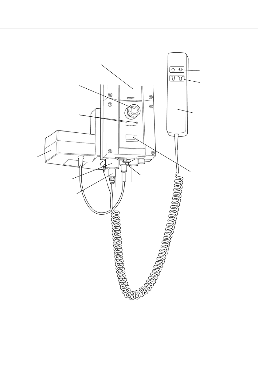
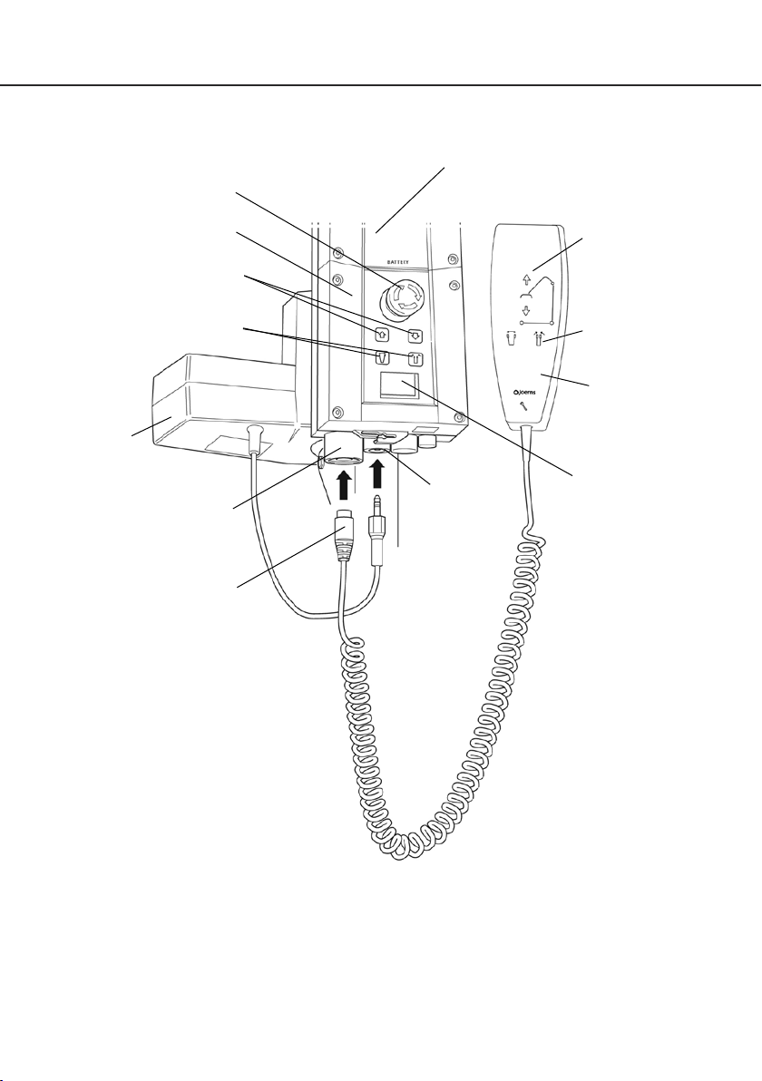
5. Standard Control Box & Handset
English
Detachable Battery Pack
Emergency Stop Button
Emergency Raise & Lower
Redundant Controls
Actuator
Handset
Connection
Socket
Handset
Connection
Plug
Actuator
Connection
Socket
Raise & Lower
Buttons
Legs Open /
Close Buttons
Handset
LCD
Information
Screen
12
Page 13
English
6. Smart Monitor & Handset
Emergency Stop Button
Detachable Battery
Pack
Hoyer
Calibre
®
Smart Monitor
Emergency Raise & Lower
Redundant Controls
Legs Open / Close
Redundant Controls
Actuator
Handset
Connection
Socket
Handset
Connection
Plug
Actuator
Connection
Socket
Raise & Lower
Buttons
Legs Open /
Close Buttons
Handset
LCD
Information
Screen
13
Page 14

®
Hoyer
Calibre
Intended Use
The Hoyer Smart Monitor is a control system for Hoyer lifts. The Smart Monitor stores useful
servicing information about the lift that can be recalled when required. This servicing information
includes:
• Number of patient lift cycles
• Total work done by actuator
• Number of lift overloads (attempted lifts above the safe working load)
• Number of days since last service interval
The Hoyer Smart Monitor contains a microprocessor inside making it possible to read out service
data via the on-board LCD screen.
Features
• Data collection in the control box with data display via LCD screen
• Work counter
• Intelligent cycle counter
• Service indicator
• Service interval indicator
• Overload information
• 3 step battery indicator
English
Benefits
• Improved safety for both patient and carer
• Accurate service data available at the touch of a button
• Optimised product life time
• Ease of maintenance for engineers and service technicians
14
Page 15
English
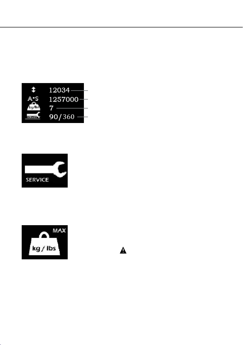
LCD Display Screen
The Hoyer Smart Monitor has the option to read out information via the LCD display screen. It is
possible to read out total lifting cycles, total work done, overloads and number of days since last
service, which can be used to quickly and easily evaluate the condition of the lift actuator.
This information is accessed by a ½ second press on the ‘UP’ button on the user handset or
redundant ‘UP’ button on the Smart Monitor.
Total Lifting Cycles
Total Work Done (Amps * Seconds)
Number of Overloads
Number of Days (since last service) /
Number of Days (between services)
Service & Usage Information
When it is time for a service, the service symbol will appear on the display. In addition, when the user handset is activated, the Smart Monitor
will give an audible signal giving notice to users that a PM check is
recommended (see recommended maintenance schedule later in this
manual).
The service symbol will be displayed each time the raise or lower keys
are depressed on the user handset.
To reset the service interval to one year, depress the leg open and leg
close keys simultaneously for five seconds.
Hoyer
Calibre
®
If the lift stops because of an overload (an attempt to lift more than the
safe working load) the overload symbol will appear on the LCD display
and the lift will cease. Lower the boom and remove excess weight.
WARNING
If the LCD display screen on your Smart Monitor has recorded
an overload, Joerns Healthcare recommend that ALL routine
daily checks are carried out on the lift prior to further use (for a
list of daily checks, please refer to your lift user manual). Joerns
Healthcare also recommend that you contact your authorised
Hoyer service provider for additional guidance.
15
Page 16
®
Hoyer
Calibre
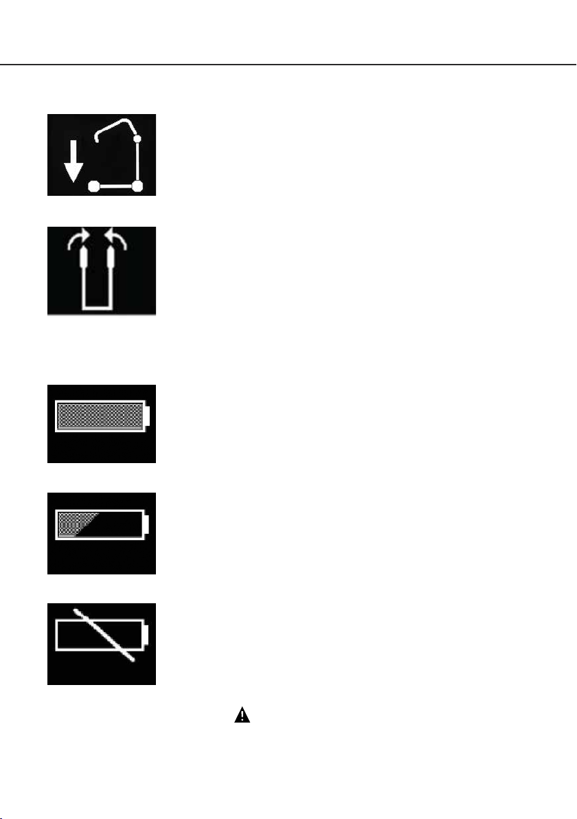
On-Board Redundant Controls
On-board redundant controls enable the lift to be raised or lowered in
the event of an emergency.
If your lift incorporates powered leg positioning, there are redundant
controls to both open and close the legs.
Battery Information
The display showing full battery means that the battery is fully charged
and the lift is ready for use.
English
The display showing a half empty battery indicates that it is time to
charge the battery.
The empty battery symbol showing on the display indicates that the
battery has no capacity left and should be placed on charge immediately.
WARNING
To avoid possible permanent damage to the battery, the battery should be placed on
charge as soon as the display indicates the half empty battery symbol.
16
Page 17

English
7. Operating Instructions
1. Leg adjustment
The legs on the Hoyer Calibre are electrically adjustable for width. The legs can be opened to
enable access around armchairs or wheelchairs. For transferring and negotiating narrow doorways
and passages the lift legs should be in the closed position.
Electric leg adjustment - is achieved by pressing the appropriate buttons on the handcontrol. The
legs will be locked whenever the handcontrol switch is released.
2. Castors and Braking
The lift has two braked castors which can be applied for parking. When lifting, the castors should
be left free and un-braked. The lift will then be able to move to the centre of gravity of the lift. If
the brakes are applied it is the patient that will swing to the centre of gravity and this may prove
disconcerting and uncomfortable.
3. Raising and lowering the boom
The movement of the boom is achieved by a powerful electric actuator which is controlled by
a simple hand control unit. The hand control has two buttons with directional arrows UP and
DOWN áâ. The actuator stops automatically at the limit of travel in both directions. The hand
control plugs into a socket at the base of the control box.
4. Emergency Stop
The red Emergency Stop Button is located on the front of the control box and is activated by
pressing in. This will cut all power to the lift and only be reset by twisting the button anticlockwise
and releasing.
Hoyer
Calibre
®
5. Redundant controls
All Hoyer lifts are fitted with raise and lower buttons on the control box. These are located
underneath the emergency stop button and can be used to lower/raise the patient should the
hand control fail.
6. Mechanical Emergency Down
In the case of a complete electrical failure the electrical actuator is fitted
with a spring loaded mechanical lowering device (RED BOSS). This
will only operate when the lift is under load. The device must twisted by
hand and released to activate. A slow decent will commence. Repeat
this process until the patient has been safely lowered.
WARNING
If this feature is used, the lift MUST be subsequently checked out by a competent engineer.
17
Page 18
®
Hoyer
Calibre
7. Batteries
The batteries are protected from deep discharge by a LOW VOLTAGE ALARM. This will sound
when the batteries need recharging and the hand control is being operated. It will not sound
independently of the hand control being operated. DO NOT IGNORE THIS WARNING ALARM.
Complete the lifting operation and place the battery on charge (see charging instructions).
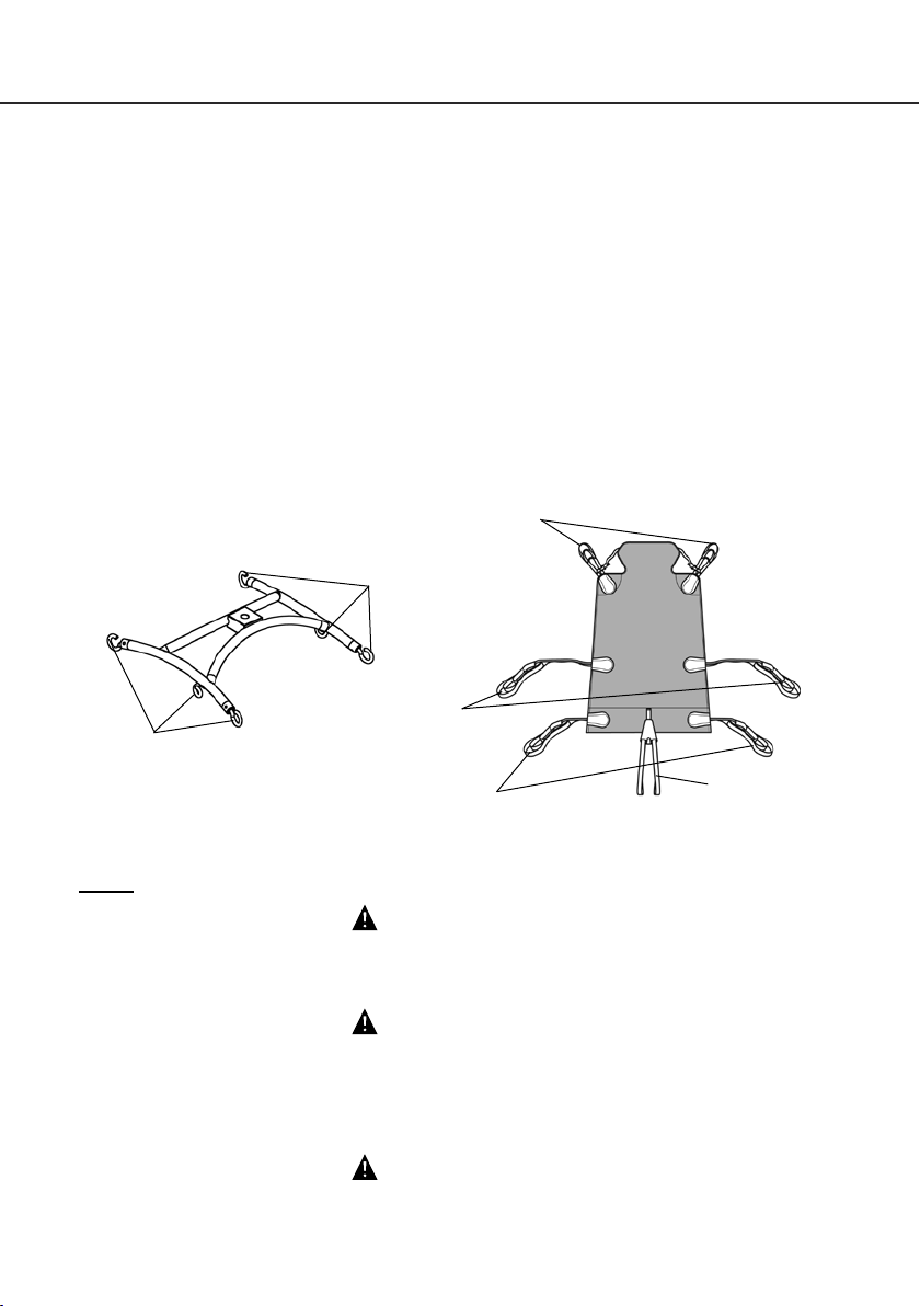
8. Slings
The Hoyer Calibre has a 6-point cradle.
The 6-point system uses slings with webbing loops, which allow positioning adjustment by selecting
different coloured loops.
Loop strap slings: Bariatric Hammock
The sling attaches to the 6-point cradle hooks via loop straps (shown below). Each sling is supplied
with comprehensive user instructions. Please ensure you have read and fully understand the
user instructions prior to use.
Shoulder Straps
Attachment
Points
English
Hip Straps
Attachment
Points
Leg Straps
6-point cradle. Example of the 6-point cradle sling with loop attachments.
NOTE: For detailed fitting instructions, please refer to the user guide supplied with each sling.
Pommel
WARNING
Joerns Healthcare recommends that slings be checked regularly and particularly before
use for signs of fraying or damage. DO NOT use slings that are worn or damaged.
WARNING
HOYER RECOMMENDS THE USE OF GENUINE HOYER PARTS. Hoyer slings and lifters
are not designed to be interchangeable with other manufacturer’s products. Using other
manufacturer’s products on Hoyer products is potentially unsafe and could result in
serious injury to patient and/or caregiver.
WARNING
Refer to maximum weight capacity of lift. Sling capacity is limited by the maximum
capacity of the lift.
18
Page 19
English
8. Removal of 6-point Cradle System
FOLLOW THESE INSTRUCTIONS EXACTLY
Your Calibre lift uses the 6-point cradle. The removal of this systems is completed by the use
of a quick-release pin. This is done quickly and easily, but you must read the following safety
instructions to ensure the 6-point cradle is safely locked into position before use.
Connection
WARNING
Two persons are required to fit the 6-point cradle OR a support table can be used.
To connect, raise the 6-point cradle up toward the boom slot.
Insert the pin sleeve through the plastic end cap to support the 6-point cradle.
Once aligned in the boom slot, reinsert the quick-release pin fully into the sleeve until it locks into
position. YOU MUST CHECK THAT THE PIN IS SECURELY FITTED.
To do this, press your finger into the barbed end. If the pin remains stationary the lift is safe to use.
Hoyer
Calibre
®
19
Page 20
®
Hoyer
Calibre
Removal
CAUTION: Be sure to support the weight of the 6-point cradle before removing pin.
To detach pin, depress the spring barb (using a flat blade electrical screw driver or similar) and
pull the pin out.
Support the 6-point cradle, and then pull the pin sleeve in the opposite direction, removing it
completely from the boom. This will release the 6-point cradle completely.
English
20
Page 21

English
Hoyer
Calibre
9. Charging Instructions
When the power pack needs charging it is removed from the lift and fitted to an off board charging unit.
1. Remove the power pack from the lift. The pack is retained by a simple latch at the top of the power
pack. Lift the latch and the power pack will be released.
2. Fit the power pack to the charging unit. The location and latching of the power pack to the charger
is the same system as used on the lift.
3. Plug the charger mains plug into a suitable mains outlet and switch the mains supply ON.
4. Charging is automatic and will fully charge the batteries over a period of four (4) hours.
Note: Even if the charger is left plugged in for extended periods it will not allow the batteries to
overcharge.
a) Green Light - Indicates main power is on.
b) Yellow Light - Indicates battery is charging.
c) Battery will be fully charged when yellow light goes off.
Note: It is recommended that the battery be charged immediately upon receipt.
5. To return the lift to service, unplug the charger and remove the power pack from the charger. Fit
the power pack to the lift and make sure the latch holding the pack in place is fully engaged. “Click”
in place. The charging of Hoyer electric lifts is simple and straightforward, but it is important to follow
the charging instructions closely. Please pay particular attention to the following points, they will
help you avoid problems with discharged batteries.
®
WARNING
• The battery, charger, hand control and control box are NOT to be opened by unauthorised
personnel. (Contact your distributor for warranty and repairs).
• DO NOT touch battery/charger terminals.
• KEEP the batteries fully charged. Place the battery on charge whenever it is not in use.
If it is more convenient to do so, place on charge every night. The charger will not allow
the batteries to overcharge.
• NEVER run the batteries completely flat. As soon as the audible warning sounds,
complete the lifting operation in hand and place on charge.
• To avoid possible permanent damage to the battery, the battery should be placed on
charge as soon as the display indicates the half empty battery symbol.
• NEVER store the battery for long periods without regular charging throughout the storage
period.
• NEVER leave the battery pack connected with the charger unit unplugged.
• DO NOT leave the charger plugged in with no battery connected.
• NEVER disconnect the charger plug by pulling on the cable.
• BE CAREFUL not to trip over the charge lead.
• DO NOT charge batteries in a bathroom or shower room.
21
Page 22

®
Hoyer
Calibre
10. Maintenance Schedule & Daily Check List
All Hoyer products are designed for minimum maintenance, however some safety checks and
procedures are required. A schedule of DAILY tasks are detailed below. Daily checks and a six
monthly service, inspection and test will ensure a lift is kept in optimum safe working condition. A
list of spare parts is available upon request.
The LOAD TEST and certification should only be carried out by qualified personnel or an
authorised service agent / dealer.
DAILY CHECK LIST: Joerns Healthcare strongly recommends the following checks be carried
out on a daily basis and before using lift.
• MAKE SURE the lift moves freely on its castors.
• MAKE SURE the 6-point cradle is free to rotate and swing
• EXAMINE & CHECK that the 6-point cradle is firmly attached to the boom.
• EXAMINE the sling hooks/clips on the 6-point cradle for excessive wear.
• MAKE SURE the legs open and close correctly.
• OPERATE the hand control to confirm the boom raises and lowers satisfactorily.
• CHECK the operation of the emergency stop button.
• CONFIRM the lift is not giving a low battery alarm when the hand control is operated. If the
alarm sounds, DO NOT use, and place on charge immediately.
• MAKE SURE the actuator connection points are secure.
• EXAMINE slings for fraying or other damage. DO NOT use any sling if damaged or if the
sling shows signs of wear.
English
Maintenance, Inspection and Test
Joerns Healthcare recommends regular inspection and maintenance. Please refer to the chart on the
next page.
22
Page 23

English
*THESE CHECKS SHOULD INCLUDE:
= Recommended
ü
1. SPREADER BAR: Check the spreader bar for freedom of rotation and
swing. Check for wear on the central pivot. Check for firm attachment to the
boom.
2. BOOM: Check the attachment of the boom to the mast. Make sure there is
only minimal side movement of the boom and the boom is free to rotate on
the boom bearing.
3. MAST: Check the operation of the mast-locking device. Make sure the mast
fully engages into the socket. Check the bottom actuator.
4. ACTUATOR: The actuator should require no maintenance other than
checking for correct operation and listening for unusual noise.
5. CONTROL BOX/SMART MONITOR: Check the function of the emergency
stop button. Inspect the hand control socket for correct fitting. Check
functioning of the hand control. Check the redundant controls and confirm
they operate as intended.
6. BATTERIES: The batteries are housed in the power pack and should not
require maintenance other than the regular charging as detailed in the
charging instructions. Check that the connections remain clean.
7. LEG ADJUSTMENT: Check the legs operate in both full extensions (inward/
outward).
8. CASTORS: Check all castors for firm attachment to the legs. Check for free
rotation of the castor and the wheels.
9. CLEANING: Clean with ordinary soap and water and/or any hard surface
disinfectant. Harsh chemical cleaners or abrasives should be avoided as
these may damage the surface finish of the lift. Avoid wetting any of the
electrical parts.
10. BASE AND WHEELS: Ensure base is even and level (all four wheels are
on the floor).
11. SLINGS: Check for wear and fraying.
12. LUBRICATION: Lubricate pivot joints with a silicone based oil, including
mast and boom connections, pedal assembly, spreader bar joint (only if
required),
13. HAND SET: Ensure plugged fully into controller.
14. QUICK RELEASE PIN: Ensure the pin is securely fitted before lifting.
15. HARDWARE: Check all nuts, bolts, screws and fasteners for excessive
wear and for tightness. Replace as required.
Hoyer
Calibre
Initially
Before
Use
ü ü ü
ü ü ü
ü ü ü
ü ü
ü ü ü
ü ü
ü ü ü
ü ü
ü ü ü
ü ü ü
ü ü
ü ü
ü ü
Annual
Service
ü
ü
®
23
Page 24

®
Hoyer
Calibre
11. Technical Specifications
Safe Working Load ................................................................................850 lbs ..................385 kgs
Maximum Overall Length ...................................................................71 inches ............... 1805 mm
Minimum Overall Length .................................................................68.5 inches ............... 1740 mm
Maximum Overall Height ....................................................................87 inches ............... 2210 mm
Minimum Overall Height .....................................................................62 inches ............... 1575 mm
6-point Cradle Maximum Height ........................................................73 inches ............... 1855 mm
6-point Cradle Minimum Height .......................................................25.5 inches ................. 650 mm
Height at Maximum Reach .................................................................68 inches ............... 1730 mm
Reach at Maximum Height ..............................................................22.5 inches ................. 570 mm
Reach at Minimum Height ...............................................................28.5 inches ................. 725 mm
Maximum Reach* ............................................................................32.5 inches ................. 825 mm
Turning Radius ...................................................................................77 inches ............... 1960 mm
Legs Open - External Width ..............................................................56 inches ............... 1420 mm
Legs Open - Internal Width ................................................................49 inches ............... 1245 mm
Legs Closed - External Width ...........................................................35 inches ................. 885 mm
Legs Closed - Internal Width ..........................................................27.5 inches ................. 700 mm
Overall Height of Legs ..........................................................................5 inches ................. 130 mm
Ground Clearance ...........................................................................0.75 inches ................... 20 mm
Front Twin Castors ...............................................................................4 inches ................. 100 mm
Rear Braked Castors ............................................................................4 inches ................. 100 mm
* Reach = centre of 6-point cradle to the front of the mast
English
Weights
Mast, Base & Boom Assembly ...............................................................240 lbs ..................109 kgs
(includes 6-point cradle)
Power Pack .............................................................................................6.6 lbs ......................3 kgs
Total ............................................................................................... 246.6 lbs ...................112 kgs
6-point Cradle ...........................................................................................20 lbs ......................9 kgs
All measurements are within a +5/--5 degree of tolerance.
24
Page 25

English
Electrical Specifications
BATTERIES.....................................................24 volt Rechargeable sealed lead acid type
BATTERY CAPACITY .....................................3.2 Ampere hours
CHARGER RATED INPUT .............................230Vac 50/60Hz
CHARGER RATED OUTPUT .........................27.4/29.0 VDC@0.8A
Electric Shock Protection
CHARGER .......................................................CLASS II
LIFT .................................................................INTERNAL POWER SOURCE
Degree of Shock Protection
CHARGER .......................................................TYPE B
LIFT .................................................................TYPE B
Environmental Conditions
Outside this environment functionality and safety may be compromised.
Operating
TEMPERATURE .............................................>+5˚C <+40˚C
RELATIVE HUMIDITY .....................................20% - 90% @ 30ºC (not condensing)
Hoyer
Calibre
®
Storage
TEMPERATURE .............................................>-10˚C <+50˚C
RELATIVE HUMIDITY .....................................20% - 90% @ 30ºC (not condensing)
ATMOSPHERIC PRESSURE .........................700 - 1060 hpa
IP Ratings
CONTROL BOX ..............................................IPX4
ACTUATOR .....................................................IPX6
OFF-BOARD CHARGER ................................IPX5
BATTERY ........................................................IPX5
HANDSET .......................................................IPX5
Duty Cycles
ACTUATOR .....................................................10% (2 mins / 18 mins)
CHARGER .......................................................4 hours (approx.)
Acoustics
A-WEIGHTED SOUND POWER LEVEL ........64dB
25
Page 26
®
Hoyer
Calibre
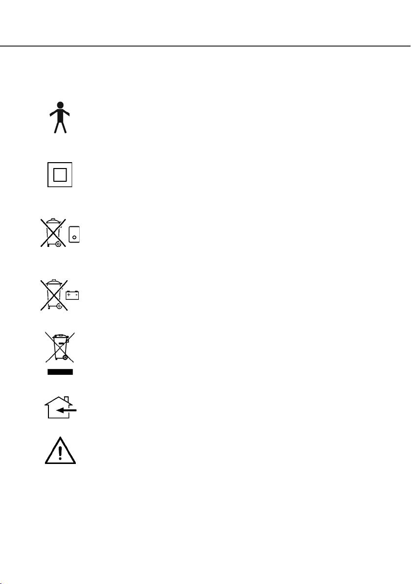
KEY SYMBOLS:
The following symbols are used on the charger, control unit and battery:
Type B equipment, as per EN 60601-1
Class 2 equipment
The disposal of the charging and control unit should not be mixed with general
household waste
The disposal of batteries should not be mixed with general household waste.
English
The disposal of electronics should not be mixed with general household waste
For indoor use
ATTENTION, consult accompanying documents.
WEEE Producers registration number WEE/GG0464RZ
26
Page 27

English
12. Warranty
This warranty covers HoyerPro lifts only. Lifts not covered under this warranty include, but are not
limited to Advance-H, HML400, HPL600WB, HPL600WBSC, HPL402, C-HLA (and variations).
HoyerPro lifts are guaranteed for a period of two years from the date of delivery against defects in
materials and workmanship under normal use and service. This warranty includes all mechanical
and electrical components.
Aluminium structural components and mechanical components on lifts are covered under warranty
for a period of five (5) years from the date of delivery.
Damage caused by use in unsuitable environmental conditions or failure to maintain the product
in accordance with user and service instructions is not covered. Any alteration, modification or
repair unless performed by or authorized in writing by Joerns Healthcare will void this warranty.
Parts
HoyerPro lifts contain various parts that wear from normal use. These parts, such as DC batteries
and casters are not covered under the two-year warranty but are covered for 90 days after date
of delivery.
Joerns Healthcare’s obligation under this warranty is limited to supplying replacement parts,
servicing or replacing, at its option, any product which is found by Joerns Healthcare to be
defective.
Warranty replacement parts are covered by the terms of this warranty until the product’s original
warranty period expires.
When requested by Joerns Healthcare, parts must be returned for inspection at the customer’s
expense. Credit will be issued only after inspection.
Hoyer
Calibre
®
Service
Most service requests handled by the facility Maintenance Department with assistance from the
Joerns Healthcare Product Service Department.
Most parts requested can be shipped next day air at the customer’s expense.
Should a technician be required, one will be provided by Joerns Healthcare, at our discretion.
Only the Joerns Healthcare Product Service Department can dispatch authorized technicians.
This warranty is extended to the original purchaser of the equipment
27
Page 28

Joerns Healthcare Inc.
2100 Design Road, Suite 100
Arlington, TX 76014 USA
(T) 800-826-0270 • (F) 800-457-8827
www.joerns.com • email: info@joerns.com
© 2014, Joerns Healthcare • 294000.10394 Rev C • DCO 14-0024
 Loading...