

Page 1
Place
Stamp
Here
JOEMEEK
D I S T R I B U T E D BY PM I A U D I O G R O U P
1845 W. 169th Street
Gardena, CA 90247
USA
ONE
Q
Joemeek User Guide
v i s i t u s o n t h e w e b a t j o e m e e k . c o m
ONE q manual.indd 4/4/05, 11:06 AM2-3
Page 2
3
JOEMEEK reborn – the legend grows
The Next Generation of Joemeek studio processors represents a quantum
leap in the history of the Joemeek legend. Long regarded for its “Big Sound”,
the original Joemeek gear was both revered and reviled for its somewhat
“quirky” nature. Now we have taken the best of what made the Joemeek
products sound great, refined it, distilled it, added to it and repackaged it.
Properly and robustly engineered for predictable, controllable performance,
the new range retains the famous Joemeek sound, with its wide, flat frequency
response extending from subsonic to ultrasonic. It also uses genuinely low
noise circuitry, with lots of headroom (immunity to overload). Accurate cali-
bration and metering, together with clear panel labelling, give you complete
confidence in what’s going on. While some equipment pays lip-service to
quality and “professional rules” but fails to deliver, the Next Generation
Joemeek products are founded on good solid electronic and audio engineering,
and withstand direct comparison with the very best names in mixers and
outboard gear.
The Joemeek range provides everything you need to get your performance
onto tape/disc.
About the Designer
The Next Generation of Joemeek has been completely re-engineered by
renowned audio electronics consultant Allan Bradford. With his background
in physics and 30 years experience with the design of instruments, mixers,
processors and amplifiers, Allan’s unique range of expertise ensures that
Joemeek remains at the forefront of music technology.
Joemeek is manufactured and
marketed under the direction of:
PMI AUDIO GROUP
USA: 1845 W. 169th Street
Gardena, CA 90247
toll free: 877-563-6335
fax: 310-323-0900
email: info@joemeek.com
UK: P.O. Box 358
Torquay, Devon TQ2 5XS
tel: +44 (0) 180 3215111
email: eusales@joemeek.com
Written by Allan Bradford, MSc
3
Contents
oneQ Controls at a Glance...............................................4
Overview............................................................................6
Preamplifier........................................................................6
Insert Point..........................................................................7
Compressor.......................................................................8
Meequalizer.......................................................................10
Enhancer..........................................................................12
De-Esser..........................................................................12
Output Stage.....................................................................12
Digital Interface..................................................................13
Using the oneQ...............................................................14
Getting Connected.............................................................14
Using the Preamp...............................................................14
Using the Compressor.......................................................15
Using the Meequalizer.......................................................15
Using the Enhancer...........................................................15
Using the De-Esser...........................................................16
Using the Output Stage......................................................16
Troubleshooting..............................................................16
Technical Specification...................................................18
ONE q manual.indd 4/4/05, 11:06 AM4-5
Page 3
5
4
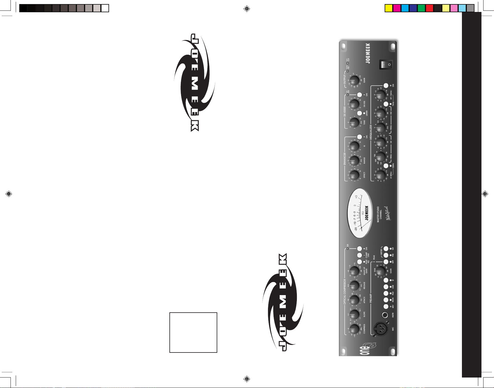
48V PHANTOM POWER switch - feeds 48V power to the microphone XLR
connector. Most condenser microphones require phantom power to operate.
IRON switch - selects transformer coupling of the Mic (XLR) inputs. The LED
lights when active.
PAD switch - selects 20dB attenuation of the Mic (XLR) inputs. The LED lights
when active.
LINE switch - selects the Line and INSTRument (1/4” jack) inputs instead of the
Mic (XLR) input. The LED lights when active.
Ø switch - reverses the phase of all inputs.
MIC input – low impedance microphone input. Parallels the Rear Panel MIC
socket. Use only one of these two sockets at a time.
INSTRument input – high impedance input. Plugging in here overrides anything
plugged into the Line input.
PREAMP GAIN - sets the amount of audio amplification. Too little gain and the
sound will be too quiet; too much and the signal could become distorted.
PEAK LED - lights 6dB below clipping.
HPF - “high-pass filter”. Mainly for use with microphones, this helps remove stage
rumble, handling noise and “pops”. The LED lights when active.
METER - analogue movement shows output signal level (VU), preamp signal
level or the amount of Compressor gain reduction (GR) in dB, depending on the
settings of the Meter switches. The momentary “PRE” switch overrides both “VU”
and “GR” metering.
COMPRESS - sets the level of signal (or “Threshold”) above which the signal
starts to be compressed.
SLOPE - sets the compression ratio applied to signals above threshold.
ATTACK - sets how quickly the compressor responds to peaks above threshold.
RELEASE - sets the time taken for the signal to return to its normal size after
compression. In general, the longer the time, the less obvious the compression.
MAKE UP GAIN - restores the level of the signal after compression.
POST EQ switch – places the Compressor after the Meequalizer in the signal
path. (When this switch is out the Compressor is before the Meequalizer in the
signal path). The LED lights when active.
COMP LINK – for stereo work, the master oneQ’s “Compress”, “Attack” and
“Release” control both master and slave oneQ (the corresponding slave oneQ’s
controls are redundant). This avoids stereo image shifts. All other controls still
operate independently on both master and slave and must be set the same for
correct stereo balance.
Compressor ON switch - turns the compressor on. The LED lights when active.
LF - controls the volume of Low Frequencies or “Bass” in the audio spectrum.
15dB of boost or cut is available at the selected frequency.
120Hz switch - sets the frequency at which the HF control operates, in for
120Hz, out for 80Hz. The LED lights when in.
LM - controls the Lower Middle frequencies in the audio spectrum. 15dB of
boost or cut is available at the selected frequency.
LM FREQ - sets the frequency at which the LM control operates, anywhere
from 200Hz to 2kHz.
HM - controls the Higher Middle frequencies in the audio spectrum. 15dB of
boost or cut is available at the selected frequency.
HM FREQ - sets the frequency at which the HM control operates, anywhere
from 1kHz to 6kHz.
HF - controls the volume of the High Frequencies or “Treble” in the audio
spectrum. 15dB of boost or cut is available at the selected frequency.
7kHz switch - sets the frequency at which the HF control operates, in for
7kHz, out for 14KHz. The LED lights when in.
EQ ON switch - turns the equalizer on. The LED lights when active.
Enhancer EFFECT – sets the amount of enhancement.
Enhancer RANGE – sets the frequency above which enhancement is applied.
Enhancer Q – adds a resonant peak at the frequency set by the RANGE
control.
Enhancer ON switch - turns the Enhancer on. The LED lights when active.
De-Esser TUNE – sets frequency at which gain reduction takes place.
De-Esser LISTEN switch – assists with tuning into the “Ess” sound by
listening to the output of the side chain filter. The LED lights when active.
DE-ESS – sets the threshold above which gain reduction is applied to the “Ess”
sound. The red “De_Ess” LED lights when gain reduction is taking place.
De-Esser ON switch - turns the Enhancer on. The LED lights when active.
OUTPUT GAIN - the volume control or “Fader” for the output of the oneQ.
PEAK FSD LED - lights 6dB below clipping. “FSD” means “Full Scale Digital”
and this LED also warns you if the Digital Interface is about to be overloaded.
‘EXT CLK’ LED - illuminates when the oneQ’s digital output is successfully
locked to an external word clock.
+4dBu/-10dBv switch - selects the operating level of the 1/4” jack output,
either to the professional +4dBu level, or to the -10dBv semi-pro level.
oneQ Controls at a Glance
ONE q manual.indd 4/4/05, 11:06 AM6-7
Page 4

7
6
Overview
The JOEMEEK oneQ is like having one channel of a professional recording
studio in one box. It takes microphones or instruments, amplifies them,
compresses and equalizes them ready to be recorded. Simple to use yet
extremely powerful, the oneQ will bring out the best in any microphone or
instrument and give the gloss of a professional studio production to all your
performances. As well as recording it will also be found useful for live work.
Think of each channel of the oneQ as six separate items of equipment:
• The Preamplifier
• The JOEMEEK Optical Compressor
• The Meequalizer
• The Enhancer
• The De-Esser
• The Fader
Preamplifier
This is the all-important front end to the oneQ. Its job is to accept any type
of microphone, instrument or other source of audio signal, and make it
loud enough. Microphones often need rather a lot of amplification, while
guitars, keyboards and CD players need less. Mics need to be connected
to low impedance inputs, while instruments prefer high impedance inputs.
To ensure correct impedance matching, the inputs are split into an XLR
connector for Mics, and 1/4” jack “Line” and “INSTRument” connectors for
everything else. A switch on the front panel decides which input connector is
active, the XLR or the 1/4” jacks. The LED next to the switch lights to show
that the Line inputs (jacks) are selected. In other words:-
Switch out (LED off) = “Mic”
Switch in (LED on) = “Line” or “Instr”
Both Mic and Line inputs are electronically balanced. Note: although
the Line input is not normally used for microphones, it can also be
suitable for some high output unbalanced microphones, such as
battery powered Electret types.
The front and rear panel Mic inputs (XLR) are balanced and wired as
follows:
Pin 2: + (hot)
Pin 3: - (cold)
Pin 1: ground
The Line input (jack) is balanced and wired as follows:
Tip: + (hot)
Ring: - (cold)
Sleeve: ground
The front panel Instrument input (jack) is balanced and wired as follows:
Tip: + (hot)
Sleeve: ground (NB: use a mono jack plug).
Note that if something is plugged into the Instrument input, anything
plugged into the rear panel Line input will be cut off.
Phantom power
Most high-quality studio mics are “Phantom powered”, which is to
say they have electronics inside them, which get their power from the
preamp. Most mics require a supply of 48 Volts, so Phantom Power is
often labelled “48V”. The “48V” switch turns this power on or off and
a red LED lights when active. When switching the Phantom Power
on, quite a loud thump may be produced, so it is a good idea to turn
down the Output Gain (or to momentarily select the Line input), when
pressing the switch.
When using dynamic or ribbon mics, do not turn Phantom Power on. It
probably won’t do any harm but it certainly won’t do any good, so leave it
off! Consult the microphone handbook if you are unsure what kind of mic
you have.
The main control, labelled “Input Gain”, covers a range of amplification
from 10dB to 60dB. In many other preamps the action of the Gain control
is rather uneven, with the 40dB to 60dB range being crammed into the last
1/6th of a turn. All Joemeek preamps use a specially designed control that
ensures smooth operation over the whole range of rotation. The (0) symbol
next to the 25dB mark, means unity gain, or 0dB, for a signal in the Line
input. Hence for Line inputs the range of gain adjustment either side of this
mark, is +35dB, -15dB.
The PEAK LED lights 6dB below clipping, so occasional brief flashes are
OK but if it’s on all the time you need to back the Input Gain off!
HPF means “high-pass filter”. Mainly for use with microphones, this helps
remove stage rumble, handling noise and “pops”. The LED lights when
active.
Technical stuff
Very low noise - does it matter? Yes and no, it all depends what you are
doing - what really matters is “signal-to-noise ratio”. All electronics produce
a certain amount of background noise - it’s in the nature of things. Providing
there is only a relatively small amount of noise, the signal will cover it up, or
“mask” it. So providing the signal is much bigger than the noise, you won’t
be aware of the noise. In other words the “signal-to-noise ratio” needs to be
a big number, ideally such as 80dB or 90dB.
So how do you achieve that in practice? The trick is to keep the microphone
as close to the sound source as possible without overloading it, so as to get
as much signal out of it as possible. Then you set the Gain control to give
only as much gain as is needed to get a decent level into the recorder.
Of course when there is no signal going on, you may hear the
background noise of the electronics. In that case, given the amount
of gain in a typical studio monitoring system, this noise “floor” should
ideally be in the region of -80dBu or lower, in order for it not to be
noticed.
The oneQ microphone preamplifier uses state-of-the-art electronics
and has an equivalent input noise of around -128dBu (with 150ohm
input load). Despite all the hyperbolae and obfuscation, the theoretical best
possible performance for silicon-based electronics is about -132dBu.
So the preamplifier design used in the oneQ and all other NextGen
Joemeek products approaches this limit. To improve significantly on
this would require highly specialised electronics and probably a vat of
liquid Nitrogen to cool it!
The maximum gain available from the preamp is 60dB, in which case
the noise floor will be -68dBu. This is actually quite noisy - if you record
that noise onto a digital recorder and play it back you can definitely
hear it. In practice of course, you do not record and play back “silence”
and the rest of the mix will probably be more than 70dB louder than
this noise and will mask it completely. Even so it is generally a good
idea not to use gains greater than 40dB or 50dB and indeed, it should
rarely be necessary to do so.
Insert Point
This is simply an unbalanced “Send and Return” jack on the rear panel.
It allows you to patch any other pieces of equipment into the signal
path, such as an effects processor or noise gate. To use it you will need
a “Y” lead wired as follows:
Tip: send
Ring: return
Sleeve: ground
ONE q manual.indd 4/4/05, 11:06 AM8-9
Page 5

9
the threshold of hearing (eg: a pin dropping onto soft carpet) to threshold of
pain (eg: standing next to a jet aircraft) - some 120dBA in all. By contrast,
vinyl, cassette tape and radio broadcasts all have a dynamic range of about
half that. Since the advent of the CD, the dynamic range of the medium is
far less of an issue and compressors are used more to give a certain “feel”
to a production. AM and FM radio however, is still very much compressed
to fit its restricted dynamic range.
5. Modification
A compressor can change the dynamics, or “envelope” of the track and it is
here that the Joemeek Compressor excels!
Types of Compressor
Most compressors work in essentially the same way: a volume-controlling
element or “gain cell” is inserted into the audio signal path. The level of the
signal at any given moment is measured and that information is used to
control the gain cell. So if the signal gets bigger, the volume is turned down.
Various types of gain cell in common use include FETs, valves (tubes),
light-dependent-resistors (photoelectric), digital potentiometers and voltage-
controlled-amplifiers, better known as VCAs.
The oneQ Compressor is a unique recreation of the sort of photoelectric
compressor used by record producer Joe Meek in the 1960’s. Using modern
components for consistency and reliability, it nonetheless reproduces faithfully
the same punchy sound that was so characteristic of the pop records of
that time.
Compression Ratio
What?? OK, it’s simpler than it sounds. If the input gets 10dB louder but the
output only increases by 5dB then the compression ratio is “2 to 1”. If the
input goes up 10dB but the output only goes up 1dB, then the compression
ratio is “10 to 1”. In a theoretically ideal compressor, this ratio is the same
for any size of signal above the threshold but for that to be true, the gain cell
and its control circuitry must be perfectly linear over a very wide range. In
practice only compressors based on VCAs and digital potentiometers
are likely to behave in this way.
Some compressors have a control to set the ratio anywhere between
1:1 (ie: no compression), and 20:1 (which would be regarded as a
“brick wall limiter”). In the oneQ the “Slope” or “Compression Ratio” is
variable from 1:1 (ie: no compression) to 10:1. Slopes around 3:1 are
gentle for vocals while higher slopes are hard for drums and guitars.
However that’s not all there is to it.
Variable Ratio
In the Joemeek optical compressor the compression ‘threshold’ is not
clearly defined and the compression ratio varies with the amount of
compression applied. Suppose the ‘Slope’ control is set to 5:1. For
signals only just exceeding threshold, the ratio is little more than 1:1.
As the compressor is driven harder, the ratio rises to 5:1, at least up to
a point. It is a feature of the Joemeek compressor that the compression
ratio actually reduces again during large transients and, adjusted correctly,
this helps to retain brightness that is often lost with other types of
compressor. This is why vintage compressors often sound more lively
than their modern counterparts.
Controls
‘COMPRESS’ sets the level of signal (the “Threshold”) above which
the signal starts to be compressed. Turning the compression control
clockwise lowers the compression threshold, and drives the compressor
harder.
‘SLOPE’ sets the average compression ratio applied to signals above
threshold. Lower settings (anti-clockwise) have less effect. Turning
the control clockwise increases the ratio and makes the effects
of compression more dramatic. At maximum (10:1) the Joemeek
compressor effectively becomes a limiter.
8
When no jack is inserted, the socket is internally linked, or “normalled”, so
that the signal flows uninterrupted. Note that the Insert Point is after the
Preamp but before the Compressor and EQ.
METER
The analogue meter displays one of three things, depending on the setting
of the “METER” switches.
In VU mode (GR switch out), the Meter shows signal level at the outputs,
after the Output Gain fader. Note that this is relative to the selected oper-
ating level of “+4dBu” or “-10dBv”. In other words if you have selected
“+4dBu” and the meter reads “0”, then you have +4dBu coming out of the
1/4” jack output socket. If you have selected “-10dBv” and the meter reads
“0”, then you have -10dBv coming out of the output jack.
In Gain Reduction mode (GR switch in), the Meter changes to read “0”dB,
when no signal is present. Whenever the compressor reduces the gain of
a signal, the meter then moves “backwards” to show the amount of gain
reduction taking place at any moment. Note that unlike many other prod-
ucts, in the oneQ this reading is a true measurement of gain reduction,
derived by comparing the input and output of the PhotoOptical gain cell.
The third mode “PRE” allows the output of the preamp to be metered
directly, rather like the “PFL” button on a mixing console. This is useful for
adjusting the gain of the Preamp. The momentary ‘PRE’ switch overrides
both ‘VU’ and ‘GR’ metering.
Compressor
The hardest device to understand, yet one of the most useful, the
PhotoOptical Compressor is what gives Joemeek products their unique
character. Its job is to make quiet sounds louder and loud sounds quieter,
or in other words to reduce the dynamic range of the programme material.
It’s a bit like manually riding the volume control, except the compressor
does it automatically, responding far quicker and more accurately than
you ever could by hand. The compressor is applied in several ways:
1. Make Sounds Stand Out
Because compressors make loud sounds quieter, you can boost the
volume of the quiet bits without the loud bits getting even louder. That
means you can raise the average level of an instrument or vocal in the
mix, which has the effect of lifting it and bringing it forwards. This can
actually improve vocals for example, bringing them out in front of a mix,
making them sound denser, more even, and more confident!
2. Crank Up The Volume
Raising the average volume of whole mixes means they can be heard
in noisy environments, such as vehicles and factories. Boosting the
average level is what makes radio stations sound LOUD and the same
technique is used on TV commercials too, which is why they always
seem annoyingly louder than the movie you were trying to watch!
3. Protection
Fast response times are generally used to control brief transients. In
other words if an occasional peak sticks its head above a maximum
permitted level, the compressor clobbers it; this is known as limiting
and a compressor designed solely for this purpose is known as a
Limiter. Limiters are primarily used to protect recorders and monitor
systems from overload, radio transmitters from overmodulation, etc.
The Joemeek compressor is not primarily intended for this purpose as
the Attack is not really fast enough to satisfy radio station requirements,
although it is generally good enough to protect recorders and monitors,
where the effect of transients is less critical. Normally you should not
hear a limiter operating but if it is driven hard constantly, it can render
a mix somewhat flat and lifeless.
4. Accommodation
The dynamic range of the human ear is phenomenal, extending from
ONE q manual.indd 4/4/05, 11:06 AM10-11
Page 6

11
The Upper Mid band can be tuned or “swept” anywhere between 1kHz
and 6kHz. Cutting the Upper Mid can reduce sibilance or other annoying
resonances. Boosting can bring out the harmonics of instruments or make
vocals more distinct. Increasing or reducing the “presence” of an instrument
or vocal in this way, can appear to move the sound forwards or backwards
in a mix.
The HF or treble section is centred at either 7kHz or 14kHz. Boosting the
14kHz band gives a sense of “air” or “sparkle” to vocals, instruments and
mixes, without boosting harsh upper-mid frequencies. Alternatively with
bass instruments, cutting this band will reduce HF noise such as hiss and
crackle. The 7kHz setting is very effective at controlling sibilance and reducing
harshness, or indeed creating it, for example by boosting the harmonics of
electric guitars.
The EQ ‘ON’ switch allows comparison between equalised and unequalised
sound (LED lights when the Meequalizer is active).
The Meequalizer is normally after the Preamplifier, the Insert Point and
the Compressor. Pressing the POST EQ switch however, places the
Meequalizer before the Compressor.
Technical stuff
Each section of the Meequalizer has a peaking or “bell” shaped frequency
res ponse, whic h will be found to be musically more satisfying than
con ventional “shelving” equalizers. The use of bell curves at LF and HF
also avoids boosting subsonics and ultrasonics which can have adverse
effects on other studio equipment, such as recorders, monitor amplifiers
and speakers. The “Q” value of the peaking filters is 0.9 (or 1.6 octaves).
Zero phase distortion ensures the best possible audio coherence.
10
‘ATTACK’ sets how quickly the compressor reacts to peaks above threshold.
Turn this control anticlockwise for a quick response. Slower (clockwise)
allows the fast leading edge of percussive sounds to pass uncompressed
for a moment, before the compressor reacts to control the gain. This
example of “changing the envelope” of a sound exaggerates the percussive
nature of drums and other instruments. Settings around mid-position are
used where the compression needs to be less obvious. Vocals for example,
require Attack times around 10msec for natural sounding results. Faster
att ack ti mes (a nti-clockwise ) in conjunc tion w ith la rge am ounts of
com pression, result in extreme “pumping ” eff ects.
‘RELEASE’ sets how long the compressor goes on squashing the sound
for, once the signal has dropped below threshold. If it stopped instantly
there would be very noticeable modulation or “pumping” of the sound. So
we may want it to stop compressing less abruptly and that is what the
Release control is for. Generally, the longer the Release time, the less
obvious is the compression. Of course some “pumping” might actually be
desirable as a special effect and that is another way in which the envelope
of a sound can be modified. The oneQ Release is variable from 100mS up
to 3 seconds giving a wide variety of effects.
How the compressor behaves actually changes with programme content
and volume. So experiment with the controls with different kinds of material to
discover the range and depth of effects that can be achieved. The ‘COMP’
in/out switch allows comparison between compressed and uncompressed
sound (blue LED lights when active). Remember that the ‘MAKE UP GAIN’
is there to restore the level of the signal after compression. Correctly
adjusted, there will be no change in volume as the Compressor ‘ON’ switch
is operated.
The Compressor is normally after the Preamplifier and the Insert Point, and
before the Meequalizer. Pressing the POST EQ switch however, places the
Compressor after the Meequaliser.
‘COMP LINK’
This is important when two oneQ’s are used together for stereo work.
When two mono compressors are used for stereo, differing amounts of
gain reduction occur in each channel, which causes the stereo image
to wander. The “Comp Link” switch avoids this problem by summing
the compressor control paths of both oneQ’s and assigning control
of the slave oneQ’s gain cell to the master oneQ. The “Compress”,
“Attack” and “Release” on the master then operate both oneQ’s and
the corresponding slave oneQ controls are redundant. Note however
that all other controls still operate independently on both oneQ’s and
must be set the same for correct stereo balance. The LED lights when
active.
Meequalizer
The oneQ “Meequalizer” is a highly effective, versatile and musically
rewarding four-band equalizer, or tone control system. Each stage
allows boost or cut of up to 15dB around the frequency in question.
The “EQ” switch turns the equalizer on, and the green LED lights when
active.
The LF band is centred at either 80Hz or 120Hz. Cutting can be used
to reduce unwanted LF noise, such as hum or rumble. Boosting can
bring out the warmth and body of bass lines and (especially around
80Hz) kick drums.
The Lower Mid band can be tuned or “swept” anywhere between
200Hz and 2kHz. It may help to think of it as like a graphic equalizer,
only instead of lots of frequency bands, you have just one, but it can
be moved to cover any given frequency band. Cutting the Lower Mid
can reduce boominess or other annoying resonances. Boosting can
bring out the body and warmth of a vocal, or the harmonics of bass
instruments.
ONE q manual.indd 4/4/05, 11:06 AM12-13
Page 7

ENHANCER
The enhancer imparts a sense of presence and clarity to all types of
programme material. It does so by analysing a range of upper mid frequencies
and synthesizing musically related harmonics, which are then added in small
quantities to the original signal.
The ‘EFFECT’ control sets the percentage of harmonics to be mixed with the
original, while ‘TUNE’ selects the range of upper mid frequencies used
for harmonic synthesis (the part of the audio spectrum above the indicated
frequency will be processed). ‘Q’ emphasizes a narrow range of frequencies
around the frequency set by the ‘TUNE’ control and this can be used to
concentrate processing on a particular band of frequencies. Using the ‘TUNE’
and ‘Q’ controls together allows the Enhancer to lift out a particular part of a
voice or mix.
The ‘ON’ switch allows comparison between processed and unprocessed
sound (LED lights when the Enhancer is active).
DE-ESSER
The De-Esser can be used to remove or reduce annoying sibilance in vocal
recordings, such as the “S” or “T” sound. It is basically a frequency-conscious
compressor that compresses only a narrow range of frequencies rather than
the whole spectrum.
The ‘TUNE’ control sets the filter to match the “Ess” frequency and the best way
to do this is to press the ‘LISTEN’ switch so as to hear only the output of the
filter, then adjust the ‘TUNE’ control until the “Ess” is at maximum loudness. The
‘DE-ESS’ control sets the amount of gain reduction within the “Ess” band.
The ‘ON’ switch allows comparison between processed and unprocessed
sound (LED lights when the De-Esser is active) and the ‘DE-ESS’ LED lights
when gain reduction is taking place.
Output Stage
‘OUTPUT GAIN’. This output volume control provides up to 10dB of
gain and also goes right down to nothing, so acting as a fader to fade
a sound out completely.
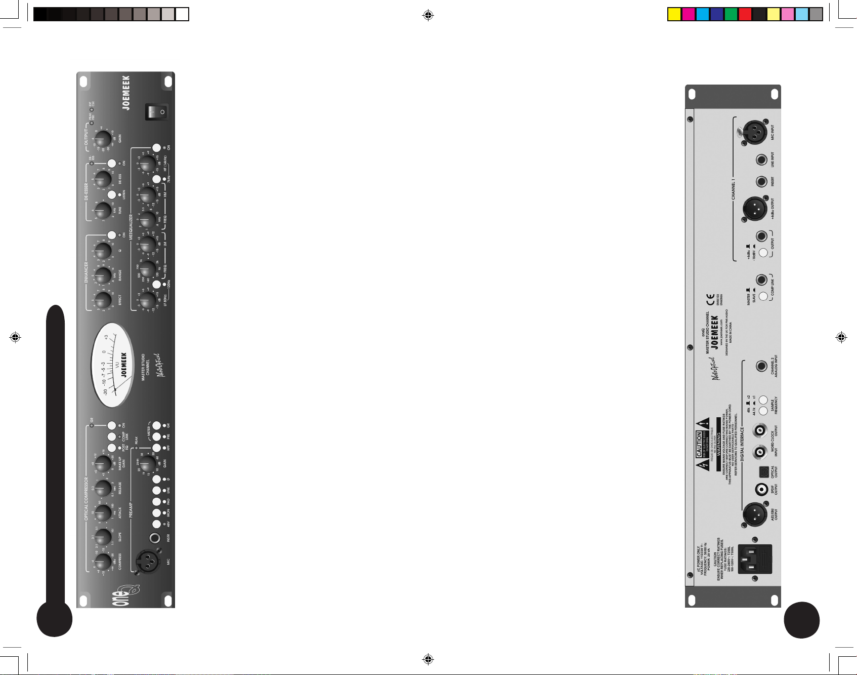
CONNECTORS
Two outputs are provided, jack and XLR, so you can simultaneously
feed (say) a recorder and a monitor amplifier. The switch adjacent to
the 1/4” jack selects the output operating level to either +4dBu (suits
most professional studio equipment) or -10dBv (suits semi-pro or hi-fi
equipment). The XLR output is always +4dBu. Check with the hand-
book for whatever you are feeding, to find out which level is required.
The XLR output is balanced and wired as follows:
Pin 2: + (hot)
Pin 3: - (cold)
Pin 1: ground
The jack output is balanced and wired as follows:
Tip: + (hot)
Ring: - (cold)
Sleeve: ground
Balanced or Unbalanced
To run the XLR output unbalanced, it will be necessary to ground pin
3 of the cable connector.
To run the 1/4” jack output unbalanced, just plug in a mono jack plug.
Either way, this increases the gain of the “+” signal by 6dB, so there is
no drop in level compared with balanced gear.
All outputs on all NextGen Joemeek products are properly balanced,
which is to say there is a signal on both pins! In this way the maximum
possible common-mode rejection of interference, can be achieved at the
receiving end.
Digital Interface
The Joemeek Digital Audio Interface provides high quality digital audio
outputs plus the ability to synchronize to an external word clock. The digital
audio outputs are compatible with most digital recorders, as well as Digital
Audio Workstations and mixers. S/PDIF format is available from the optical
and RCA phono connectors, while the transformer coupled XLR connector
provides an AES3 compatible output.
The Joemeek Digital Interface has highly stable onboard master clocks for
low-jitter, hi-fi results. Internal sample rates of 44.1kHz, 48kHz, 88.2kHz
or 96kHz are selected by means of rear panel switches. 44.1kHz is the
standard used for audio CD’s, while 48kHz and 96kHz are widely used
in recording studios. In general, the higher the sample rate, the better the
audio fidelity, but the more disk space is required for the recording. For
example, recording at 96kHz requires twice as much storage as 48kHz.
Consult the manual of your recorder or DAW as to what sample rates it will
accommodate.
Alternatively the oneQ may be set to the frequency of an external master
word clock, generated, for example, by the studio’s recorder or DAW. When
connected to the BNC socket provided, a suitable external word clock will
be detected automatically and will override the oneQ’s internal word clock.
The front panel LED labelled ‘EXT CLK’ illuminates when the oneQ is
successfully locked to an external word clock.
To avoid distortion, care should be taken not to overdrive the input to the
Digital Interface. The red LED next to the Output Gain control is labeled
“PEAK FSD” which stands for “Full Scale Digital”. Occasional flashes are
OK but if it is on all the time, turn something down!
Note that the Digital Interface is a two-channel device, with channel
one fed by the oneQ’s internal circuitry. In order to utilize the second
digital channel, an external analog input is provided in the form of a
balanced 1/4” jack on the rear panel wired as follows:
Tip: + (hot)
Ring: - (cold)
Sleeve: ground
In this way the output of the oneQ and another analog source can be
fed into one digital input of a recorder or digital workstation.
12
13
ONE q manual.indd 4/4/05, 11:06 AM14-15
Page 8

15
Using the Compressor
Start with the Compressor and Meequalizer off and adjust the input and
output gain so that the VU Meter reads around 0dB. Now switch the meter
to read gain reduction using the ‘GR’ pushbutton.
Set ‘COMPRESSION’ and ‘ATTACK’ fully anti-clockwise, with ‘SLOPE’ and
‘RELEASE’ at mid-position. Press the Compressor “ON” push-button and
turn up the ‘COMPRESSION’ control until the compressor GR meter starts
to read 3dB or 5dB on audio peaks. You should now be able to hear the
compressor working as the volume diminishes. Use the ‘MAKE UP GAIN’
control to restore the signal to its previous (uncompressed) level. Alter the
SLOPE and listen to how the severity of the gain reduction changes. Try
changing the Attack and listen for percussive sounds getting louder.
Reducing the Attack and Release times should emphasise this even more
and the compressor should start to “pump” audibly.
The overall result of compression depends on the combined settings of the
Compress, Slope, Attack and Release controls. Experiment with different
combinations to discover what best suits the material you wish to compress.
Watch the GR meter and don’t overdo things - it’s possible to apply 20dB of
gain reduction before you realise it!
Use the Compressor ‘ON’ switch to make comparisons between compressed
and uncompressed signals.
Using the Meequalizer
Always start with the Meequalizer boost/cut controls (LF, MID and HF) set
to “0” (the control knobs set vertically, in their centre notches). This setting
is also known as “flat”.
You need to be careful about too much boost or “lift”, since boosting
takes the oneQ closer to overload. The oneQ has generous overload
margins but when a lot of boost is used, it may be necessary to com-
pensate by reducing the Output Gain or the Input Gain (the latter will
affect the Compressor setting though).
Keep an eye on the VU Meter when adjusting the EQ. When the red
LED (labeled “PEAK FSD”) lights, the oneQ is within 6dB of clipping.
Occasional flashes are OK but if it is on all the time, turn something
down!
The way to use the LMF and HMF controls, is to apply quite a lot of
boost, then sweep the frequency until you “tune in” to the sound you
are interested in. Once you find it, adjust the amount of boost or cut to
give the desired effect.
Experiment with combinations of settings of EQ and try to picture how
the audio signal is being affected. Use the EQ ‘ON’ switch to make
comparisons between EQ’d and non-EQ’d signals.
Using the Enhancer
Press the ‘ON’ switch and set the ‘EFFECT’ control to mid position and
the ‘Q’ control fully anticlockwise. Use the ‘TUNE’ control to change the
character of the resulting enhancement.
14
Using the oneQ
GETTING CONNECTED
The figure shows the oneQ being used instead of a mixing desk in a
recording setup:
• A microphone is connected to the Mic Input
• A guitar is connected to the Instrument Input
• The insert point is being used to divert the preamplified signal through
an external effects processor
• The recorder output is connected to the Line Input for playback.
Previously recorded tracks may also be replayed via the Line Input,
to permit compression and equalization
POWER SUPPLY
Connect the oneQ power cord to the AC connector on the rear panel
and switch on the mains supply. NB: ensure that the oneQ is set to the
correct mains voltage for your region – either 115V or 230V. Orientate
the fuse holder / mains voltage selector draw so that the required volt-
age appears at the top. If in doubt consult a competent engineer.
Using the Preamp
Turn the ‘INPUT GAIN’ control to minimum and connect the input
source. If you are using a condenser microphone, remember to switch
on the 48V Phantom Power. Set the ‘OUTPUT GAIN’ to “0dB”. Turn
up the ‘INPUT GAIN’ until the microphone sound registers on the VU
Meter, adjusting it so that the meter reads between “0” and “+3” on
sound peaks. When the red LED (labeled “Peak”) lights, the oneQ is
within 6dB of clipping. Occasional flashes are OK but if it is on all the
time, turn the Input Gain down!
Remember you can check the preamp gain at any time by pressing
the “Meter Pre” button.
ONE q manual.indd 4/4/05, 11:06 AM16-17
Page 9

17
5) Too little or too much compression
• Turn the ‘Input Gain’ control up or down respectively, to adjust the
signal level to the compressor
6) The Meequalizer doesn’t work.
• Is the EQ ‘ON’ switch in (LED on)?
• Is ‘Input Gain’ control turned up?
• Is ‘Output Gain’ control turned up?
7) The Enhancer doesn’t work
• Is the Enhancer ‘ON’ switch in (LED on)?
• Is ‘Effect’ control turned up sufficiently?
• Does the programme material contain only low-bass frequencies?
8) The De-Esser doesn’t work
• Is the De-Esser ‘ON’ switch in (LED on) and the ‘LISTEN’ switch out
(LED off)?
• Is ‘De-Ess’ control turned up?
• Does the programme material contain only low frequencies?
9) Too much noise
• Is the ‘Input Gain’ control too high? Try moving the mic closer
to the source
• Is the ‘Output Gain’ control too high (eg: when lots of compression is
being used)?
• Is there too much EQ boost?
• Is the noise already present in the input signal? (Try removing the input)
10) Sounds distorted
• Is the ‘Input Gain’ control too high?
• Is the ‘Output Gain’ control too high?
• Is there too much EQ boost?
• When using the compressor, is the Release control set too low?
• Is the Enhancer on with the ‘Effect’ control set too high and/or the
‘Tune’ control set too low?
16
Then turn up the ‘Q’ control and use the ‘TUNE’ control to hunt around for
particular elements of a voice or mix. With the Enhancer you will usually find
that “less is more” and it is as well to keep the ‘EFFECT’ and ‘Q’ settings
fairly low. It is very easy to add too much harmonic and though the effect can
be dramatic at first, it will soon become wearing and contribute to listening
fatigue. If you can hear audible distortion creeping in you are definitely over-
doing it, so turn down the ‘EFFECT’ control and/or raise the ‘TUNE’ setting.
Use the ‘ON’ switch to mak e comparisons between processed and
unp rocessed sound. The nature of harmonic enhancement is such that you
may not realise how much effect it is having until you turn it off!
Using the De-Esser
Set the ‘DE-ESS’ control fully anticlockwise. Press the ‘ON’ and ‘LISTEN’
switches so as to hear only the (somewhat shrill) output of the filter, then
adjust the ‘TUNE’ control until the “Ess” sounds are at maximum loudness.
Turn the ‘LISTEN’ switch off again and advance the ‘DE-ESS’ control until
the sibilance is reduced to an acceptable, natural sounding level.
Be sure that the ‘LISTEN’ switch is off (out) prior to any recording!
Use the ‘ON’ to make comparisons between processed and unprocessed
sound.
Using the Output Stage
Final adjustments to the output level can be made with the OUTPUT Gain
control, again keeping an eye on the VU meter and PEAK FSD LED. Note
how this control can also be used to fade out the signal completely.
Troubleshooting
1) No Power (no lights work)
• Is the power supply plugged in (both ends)?
• Is the mains power on?
• Is the mains voltage set correctly for your region?
• Has the mains fuse blown?
2) The microphone doesn’t work
• Is it connected to the correct (XLR) input on the front or rear panel?
• If it is a condenser microphone, is the phantom power switched on?
• Is the ‘Line’ switch out (LED off)?
• Is the ‘Input Gain’ control turned up?
• Is the ‘Output Gain’ control turned up?
3) The line input doesn’t work
• Is the source connected to the correct (jack) input on the back of the
unit?
• Is the ‘Line’ switch in (LED on)?
• Is the ‘Input Gain’ control turned up?
• Is the ‘Output Gain’ control turned up?
4) The compressor doesn’t work
• Is the Compressor ‘ON’ switch in (LED on)?
• Is the ‘Compress’ control turned up enough?
• Is the ‘Slope’ control turned up enough?
• Is there enough signal, as set by the ‘Input Gain’ control, to drive the
compressor?
ONE q manual.indd 4/4/05, 11:06 AM18-19
Page 10

18
Technical Specification
Input impedances Mic: 1.2kohm; Line: 20kohm
Pre-amp overall gain 10dB to 60dB (variable)
Common mode rejection 70dB
Equivalent input noise -128.5dBu (unweighted)
Distortion 0.001%
(below Compressor threshold)
Frequency response 15Hz to 70kHz (-3dB)
Maximum input before clipping Mic: +21dBu; Line: +45dBu
Headroom before clipping +21dBu
Pad 20dB attenuation
High Pass Filter 12dB per octave cut below 80Hz
Compressor threshold -6dBu to +22dBu (variable)
Compressor ratio 1:1 to 10:1 (variable)
Compressor attack time 1 msec to 100 msec (adaptive)
Compressor release time 0.1 sec to 3 sec (adaptive)
EQ Boost and Cut +/-15dB (zero phase-shift bell response)
EQ “Q” 0.9 (1.6 octaves
LF Frequency 80Hz/120Hz switchable
LMF Frequency 200Hz to 2kHz variable
HMF Frequency 1kHz to 6kHz variable
HF Frequency 7kHz/14kHz (selectable)
Nominal output levels +4dBu/-10dBv
Output impedance 100 ohm
Output Level switch 12dB attenuation
Noise Floor -85dBu (typical, with ~40dB mic gain)
VU Meter Analogue movement
Power supply 115V / 230V ac mains, 50/60Hz
Power consumption 30W
Mechanical 482W x 88H x 220D (overall)
Weight 3 kilos
Notes
ONE q manual.indd 4/4/05, 11:06 AM20-21
Page 11

Notes
replacement by Purchaser of any Product or part thereof shall extend
the warranty period as to the entire Product. The specific warranty on
the repaired part only shall be in effect for a period of ninety (90) days fol-
lowing the repair or replacement of that part or the remaining period of
the Product warranty, whichever is greater.
2. Exclusive Remedy: Acceptance: Purchaser’s exclusive remedy and
PMI’s sole obligation is to supply (or pay for) all labor necessary to
repair any product found to be defective within the warranty period
and to supply, at no extra charge, new or rebuilt replacements for
defective parts. If repair or replacement fails to remedy the defect, then
and only in such an event, shall PMI exchange to Purchaser a new or
reconditioned unit. Purchaser’s failure to make a claim as provided in
paragraph 1 above or continued use of the product shall constitute an
unqualified acceptance of such Product and a waiver by Purchaser of
all claims thereto.
3. Exceptions to Limited warranty: PMI shall have no liability or obligation
to Purchaser with respect to any Product subjected to abuse, improper
use, negligence, accident, modification, failure of the end-user to follow
the operating and maintenance procedures outlined in the users manual,
attempted repair by non-qualified personnel, operation of the unit
outside of the published environmental and electrical parameters, or
if such products original identification (trademark, serial number) markings
have been defaced, altered, or removed. PMI excludes from warranty
coverage, Products sold AS IS and/or WITH ALL FAULTS and excludes
used products which have not been sold by PMI to the Purchaser. PMI
also excludes from warranty coverage consumables such as fuses and
batteries, tubes, etc.
4. Proof of purchase: The dealer’s dated bill of sale must be retained as
evidence or the date of purchase and to establish warranty eligibility
Joemeek Limited Warranty
THIS PRODUC T IS FOR PROFESSION AL USE ONLY
PMI Audio Group warrants that all products will be free from defects in mate-
rial or workmanship:
A: For a period of (3) three years from the date of purchase (hereinafter the
labor warranty period), PMI Audio Group will repair or replace this Product if
determined to be defective. After the expiration of the labor warranty period,
the Purchaser must pay labor charges.
B: In addition, PMI Audio Group will supply, at no charge, replacements for
defective parts for a period of (three years) from the date of purchase. During
the labor warranty period, to repair the Product, Purchaser must return the
defective Product, freight prepaid, or deliver it to PMI Audio Group Service
Center. The product to be repaired is to be returned in either its original car-
ton or a similar package affording an equal degree of protection. PMI Audio
Group will return the repaired Product freight prepaid to the Purchaser. PMI
Audio Group is not obligated to provide Purchaser with a substitute unit dur-
ing the warranty period or at any time.
Conditions
1. Notification of claims: Warranty Service: If Purchaser discovers that the
Product has proven defective in material or workmanship, then written notice
with an explanation of the claim shall be given promptly by Purchaser to PMI
but all claims for warranty service must be made within the warranty period. If
after investigation PMI determines that the reported problem was not covered
by the warranty, Purchaser shall pay PMI for the cost of investigating the
problem at its then prevailing time-and-materials rate. No repair or
ONE q manual.indd 4/4/05, 11:06 AM22-23
Page 12

Disclaimer of Warranty
EXCEPT FOR THE FORGOING WARRANTIES, PMI HEREBY DISCLAIMS AND EXCLUDES ALL
OTHER WARRANTIES, EXPRESS OR LIMITED, INCLUDING, BUT NOT LIMITED TO ANY/OR ALL
IMPLIED WARRANTIES OF MERCHANT ABILITY, FITNESS FOR A PARTICULAR PURPOSE AND/
OR ANY WARRANTY WITH REGARD TO ANY CLAIM OF INFRINGEMENT THAT MAY BE PROVED
IN SECTION 2-312(3) OF THE UNIFORM COMMERCIAL CODE AND/OR IN ANY COMPARABLE
STATE STATUE. PMI HEREBY DISCLAIMS ANY REPRESENTATIONS OR WARRANTY THAT
THE PRODUCT IS COMPATIBLE WITH ANY COMBINATION OF NON-PMI AUDIO PRODUCTS
PURCHASER MAY CHOOSE TO CONNECT TO THE PRODUCT.
Limitation of Liability
THE LIABILITY OF PMI, IF ANY, AND PURCHASER’S SOLE AND EXCLUSIVE REMEDY FOR
DAMAGES FOR ANY CLAIM OF ANY KIND WHATSOEVER, REGARDLESS OF THE LEGAL
THEORY AND WHETHER ARISING IN TORT OR CONTRACT, SHALL NOT BE GREATER
THAN THE ACTUAL PURCHASE PRICE OF THE PRODUCT WITH RESPECT TO WHICH SUCH
CLAIM IS MADE. IN NO EVENT SHALL PMI BE LIABLE TO PURCHASER FOR ANY SPECIAL,
INDIRECT, INCIDENTAL, OR CONSEQUENTIAL DAMAGES OF ANY KIND INCLUDING, BUT
NOT LIMITED TO, COMPENSATION, REIMBURSEMENT OR DAMAGES ON ACCOUNT OF THE
LOSS OF PRESENT OR PROSPECTIVE PROFITS OR ANY OTHER REASON WHATSOEVER.
Info rmati on in thi s User G uide is su bject to chang e withou t notice . No part of this User Guid e may be re produced
or transm itted in any form or by any means, elec tronic, mech anical or by any other mea ns, for any purpos e,
with out the express written per missi on of PMI Au dio Gro up.
PMI Audio G roup may h ave trad emarks, cop yrights or other int ellec tual proper ty rights cov ering the sub ject
matt er of t his U ser Guide. Exce pt as expr essly provide d in any writte n agr eement from PMI A udio Group, the
furn ishin g of this Us er Gui de is provide d for the so le use of t he auth orized User [or Service Agent where appli -
cabl e] and d oes n ot give the Us er an y lice nse t o use an y tra demarks, copyr ights or o ther intell ectual proper ty
of P MI Audio Gro up.
PMI , PM I A UDIO, T ED FLE TCHER, M EEQUAL IZER, STU DIO PROJ ECTS, JOE MEEK, T OFT AUDI O
DES IGNS , C URRENT SENSE, ME EKROPH ONE, TR AKPAK, an d ( If it So unds Ri ght... It i s R ight !) a re
eith er regi stered tr adema rks o r trade marks of PM I A udio Grou p in the U .S.A. and /or o ther count ries.
Copy right © 200 5 PM I Audi o Group . All ri ghts re served.
Owners Registration Card
T O B E C O M P L E T E D A T TI M E O F P U RC H AS E
Name _____________________________________________
Date of Purchase ____________________________________
Serial Number ______________________________________
Dealer’s Name ______________________________________
R E TA IN F O R Y O U R R E CO R D S
P L E A S E D I S P A T C H A N D R E T U R N
Y O U R RE G I ST R AT I O N
T O J OE M E EK W I T H IN 1 4 D AY S
O F P UR C H A SE
Specifications and model numbers are subject to
change without notice
Product Registration Information
Please Fill in the Below Sections and Return
Name:
Address:
City: State: Zip Code:
Telephone Number: email Address:
Model Purchased: Date Purchased:
Serial Number: Dealer:
Comments:
What magazines do you read to influence your buying decision: (please check all that apply)
❏
MIX
❏
Electronic Musician
❏
EQ
❏
Sound on Sound
❏
Pro Audio Review
❏
Recording
❏
Pro Sound News
❏
Audio MIDI
ONE q manual.indd 4/4/05, 11:06 AM24-25
 Loading...