

Page 1
DATA SHEET
For Routing Infrared
Commands from Two IR
Receivers to Five Sources
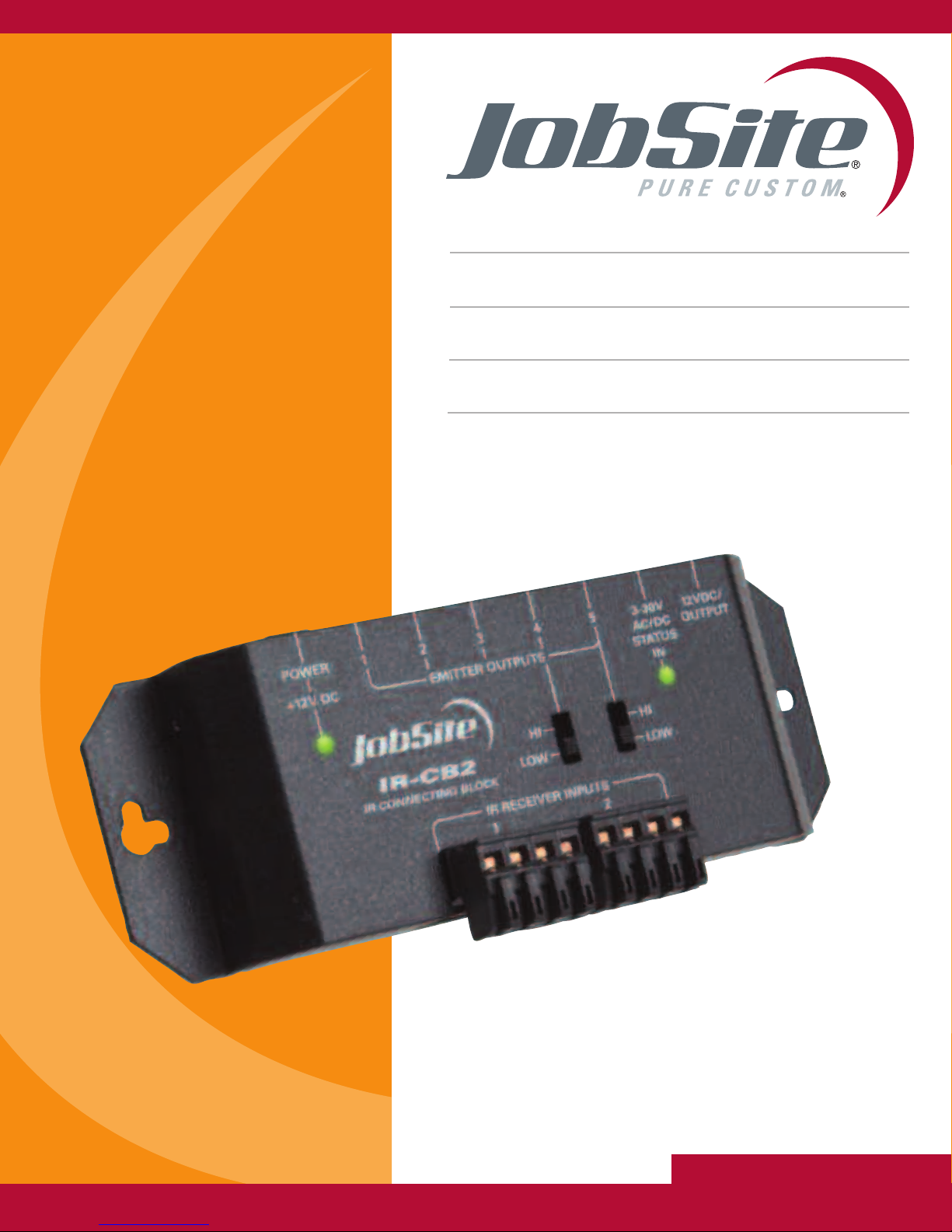
TWO ZONE IR CONNECTING BLOCK
IR-CB2
Page 2

IR-CB2
TWO ZONE IR CONNECTING BLOCK
FEATURES
• Provides two IR receiver inputs to accommodate receivers with
Zone 2 capabilities
• Selectable high/low emitter outputs for use with IR-E1HO high output emitter
r single and dual emitters
o
• 12V DC status input jack and LED indicator
INSTALLATION FRIENDLY DESIGN:
• Snap and lock connector secures wire in place without the use of a
screwdriver
• Wings allow for either vertical of horizontal mounting
• 3.5mm emitter output jacks
• Includes in-line UL listed regulated power supply
SPECIFICATIONS
• IR system: Works with practically all brands of IR remote controls
• Connections: 2 receiver inputs, 5 emitter outputs
• Home runs required from each IR receiver
WIRING REQUIREMENTS:
• Category 5 or better
MOUNTING:
• Wall or flat surface: use drywall screws
DIMENSIONS:
• 5-11/16” wide x 1-1/4” high x 2” deep
POWER REQUIREMENTS:
110V to 12V DC power supply (included)
•
ARRANTY
W
• 2 year limited
:
JOBSITE SYSTEMS
1 SW 130 STREET
3
23
1
MIAMI, FL 33186
TWO ZONE IR CONNECTING BLOCK
P 866.4JB.SITE (866.452.7483)
F 305.238.0185
WWW.JOBSITESYSTEMS.COM
IR-CB2
Page 3
PREPARING FOR INSTALLATION:
12VDC/
OUTPUT
HI
LOW
HI
LOW
1
1
2
23 54
EMITTER OUTPUTS
POWER
+
12V DC
IR RECEIV
ER INPUTS
3-30
V
AC/DC
STA
TUS
IN
IR-CB2
IR CONNECTING BLOCK
The IR Receiver cables, Emitter cables and the 12V DC power supply cable must
all reach the proposed location of the IR-CB2 connecting block. Mark the cables
with Wire labels, describing where the cables originate from, rather than where
hey will terminate. Locate a local un-switched AC outlet to be used to power the
t
IR-CB2 power supply.
INSTALLATION:
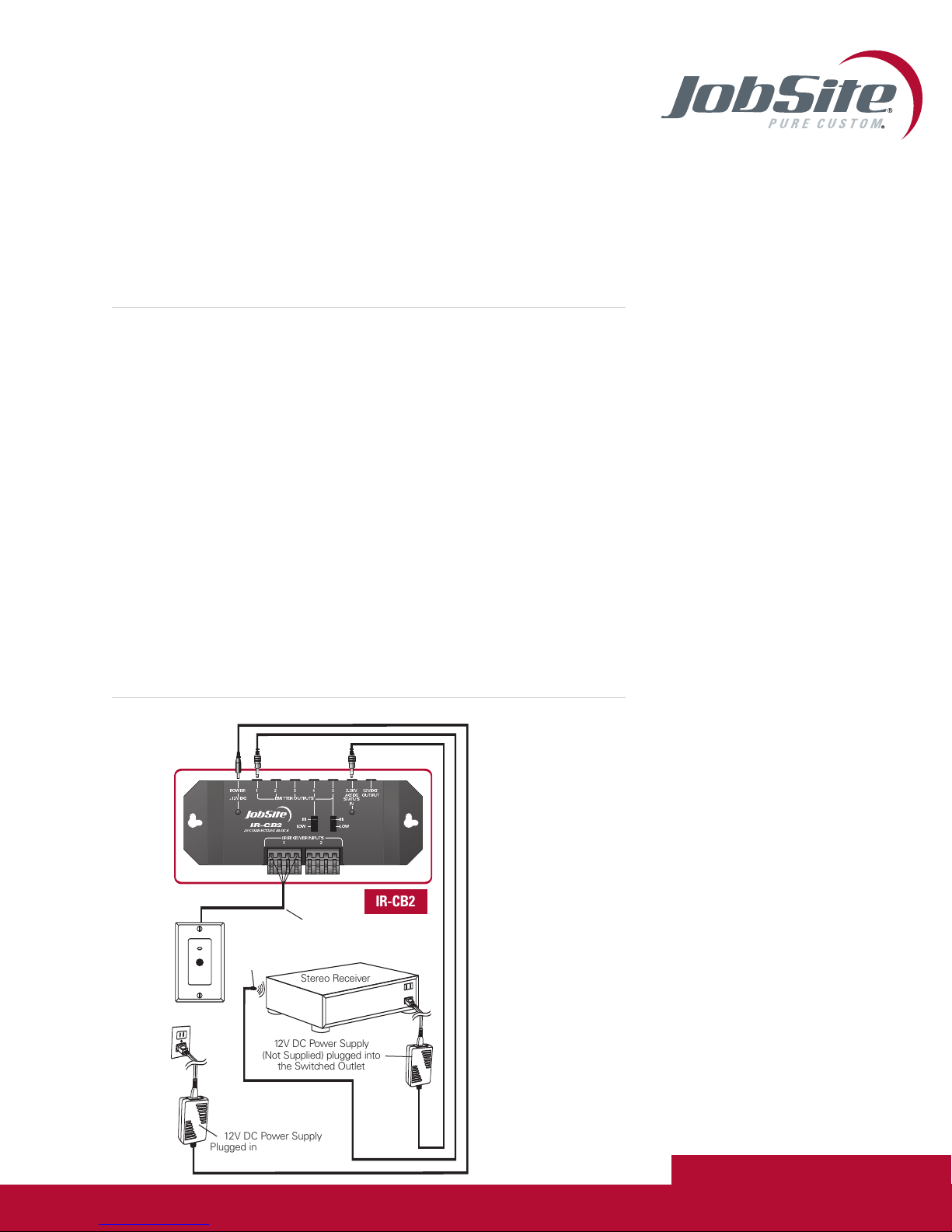
1. Select an appropriate location for the IR-CB2
2. Run all the necessary wiring to the IR-CB2. Label the wires for future
reference.
3. Plug the supplied 12V DC power supply into the un-switched AC outlet.
4. Plug the 12V DC power supply connector into the IR-CB2 socket marked
POWER.
5. After verifying that the AC outlet works, unplug the power supply connector.
6. Strip 1/4" of insulation from the end of each CAT5 wire.
7. Locate the Snap and lock connectors and remove them if they are plugged in.
8. Use a small flathead screwdriver or your thumb to raise the locking tabs,
exposing the holes on the connectors.
9. Insert each wire into the appropriate hole and snap down the locking tabs.
10. Insert the smooth side of the connector plug into the smooth side of the
IR-CB2 socket.
11. Connect the Emitters to the Emitter outputs.
12. Plug the 12V DC power supply connector into the IR-CB2 socket marked
POWER.
IR-CB2 INSTALLATION DIAGRAM
IR-WMR
Plugged into an Unswitc
C Outlet P
A
Categor
obSite
J
IRE1
Emit
ter
Stereo Receiver
12V DC Power Supply
(Not Supplied) plugged into
witched Outlet
the S
12V DC Power Supply
ers the S
w
o
5 Wire
hed
ystem
JOBSITE SYSTEMS
12331 SW 130 STREET
MIAMI, FL 33186
IR-CB2
y
P 866.4JB.SITE (866.452.7483)
F 305.238.0185
WWW.JOBSITESYSTEMS.COM
©2004 Niles Audio Corporation. JobSite,
Pure Custom and Niles are registered
trademarks of Niles Audio Corporation
and the JobSite Logo is a trademark of
Niles Audio Corporation. JSIRCB2PDF
Specifications subject to change without notice.
TWO ZONE IR CONNECTING BLOCK
IR-CB2
Page 4

 Loading...