

Page 1

The JOBO ATL's 2200 / 2300 / 2400 / 2500
Wir stellen vor: Die JOBO ATL's 2200 / 2300 / 2400 / 2500
The AutoLabs ATL 2200/2300/2400 and 2500 are the newest user-programmable, fully automatic developing processors in the
JOBO product line. With the very many tanks and drums available, the Autolab is perfectly suited for a variety of processing
needs. The unit is completely user-programmable, enabling you to programme developing times and temperatures for different
processes, whereby the unit is ready for developing operations within a few minutes.
All functions needed for photographical development, except for stabilizing and drying, are fully automatic in the ATL. The
temperature control system of the water jacket reacts to deviations of 1/10th of a degree. The bottles with the solutions to be
processed as well as the rotating drum are kept at process temperature by the water jacket. The rotary movement is controlled by
the microprocessor. Pre-warmed solutions are pumped from the supply containers into the developing drum by means of a
compressed air system. The built-in computer shows how much solution is left in the storage containers. Consequently, your ATL
will not permit the starting of a process if there is not enough solution. The microprocessor also controls the timing of each
developing and rinsing step. Besides, the ATL permits you the recovery of each used solution, because all chemicals are collected
separately. The recovery and reprocessing of used chemicals makes processing with your ATL even more profitable and permits
a non-polluting, economically priced waste disposal.
FEATURES:
QUALITY
· Fully automatic processing using a sophisticated microprocessor control system
· Consistent results run to run and day to day
· Each process step is accurate to the second
JOBO - das heißt über 60 Jahre Erfahrung in Papier- und Filmentwicklungstechnologie.
Die Autolabs ATL-2200/2300/2400/2500 sind die neusten freiprogrammierbaren, voll- automatischen Entwicklungsgeräte in
der JOBO ATL Palette. Bei der großen Vielfalt von verfügbaren Tanks und Trommeln ist das Autolab bestens für Arbeiten
verschiedenster Größenordnungen geeignet. Da es vollkommen bedienerprogrammierbar ist, können Sie Entwicklungszeiten und
-temperaturen für verschiedene Prozesse einspeichern und innerhalb von wenigen Minuten entwicklungsbereit haben.
Alle für die fotografische Entwicklung notwendigen Funktionen, außer der Stabilisierung und Trocknung, sind beim ATL
vollautomatisch.
Die Temperaturregelung des Wassermantelbades arbeitet auf 1/10 Grad genau.
Sowohl die Flaschen mit den zu verarbeitenden Chemikalien als auch die rotierende Trommel werden durch das Wassermantelbad
auf Prozeßtemperatur gehalten.
Die Rotationsbewegung sowie der Drehrichtungswechsel werden durch den Mikroprocessor gesteuert. Temperierte Chemikalien
werden mittels eines Druckluftsystems von den
Vorratsbehältern in die Entwicklungstrommel gepumpt. Der eingebaute Computer zeigt, welche Menge an Chemikalien in den
Vorratsbehältern verblieben ist. Folglich läßt Ihr ATL das Starten eines Prozesses nicht zu, wenn nicht genügend Chemikalien
vorrätig sind. Der Mikroprocessor steuert ebenfalls den Zeitablauf jedes Entwicklungs- und Wässerungsschrittes. Außerdem
ermöglicht Ihnen das ATL die Rückgewinnung jeder verbrauchten Lösung, da sämtliche Chemikalien getrennt aufgefangen
werden. Die Rückgewinnung und Wiederaufbereitung verbrauchter Chemikalien macht die Entwicklung mit Ihrem ATL noch
wirtschaftlicher, bzw. ermöglicht eine umweltgerechte, preiswerte Entsorgung.
MERKMALE:
QUALITÄT
· Vollautomatisch durch Mikroprozessorsteuerung
· Konstante Ergebnisse von Prozeß zu Prozeß
· Jeder Prozeßschritt auf die Sekunde genau
ECONOMIC EFFICIENCY
· Thorough use of chemicals
· Intelligently designed heating system to lower your electric bill
· Chemical recovery for silver reclamation
FLEXIBILITY
· Quickly and easily switch from one process to another
· All common processes are handled: e.g. C-41, E-6, Ciba/TM, B/W, Ilfochrome (Ciba), R 3, RA-4, lithographic, x-ray
· Any format: e.g. roll film, miniature film, sheet film from 6x9 to 21x30 cm, larger formats available on request
· Paper formats from 7x10 to 50x60
We are able to produce special units in accordance with your specifications for film formats up to 50x60 cm, and spirals for
film lengths up to 8 metres and up to 127 mm in width.
WIRTSCHAFTLICHKEIT
· Gute Ausnutzung der Chemikalien
· Automatische Temperaturkontrolle des gesamten Systems
· Eingebaute Chemikalienauffangvorrichtung
VIELSEITIGKEIT
· Direktes Wechseln zwischen verschiedenen Prozessen
· Alle Prozesse sind möglich: z.B. C-41, E-6, Ciba/TM, S/W, R-3, RA-4, Litho, Röntgen
· Jedes Format: z.B. Rollfilm, Kleinbild, Planfilm von 6x9 bis 21x30 cm,
größere Formate auf Anfrage
· Papiergrößen von 7x10 bis 50x60
Wir fertigen Sonderanfertigungen nach Ihren Vorgaben für Filmformate bis 50x60cm, sowie Spiralen für Filmlängen bis 8
Meter und bis 127 mm Breite.
1
Page 2
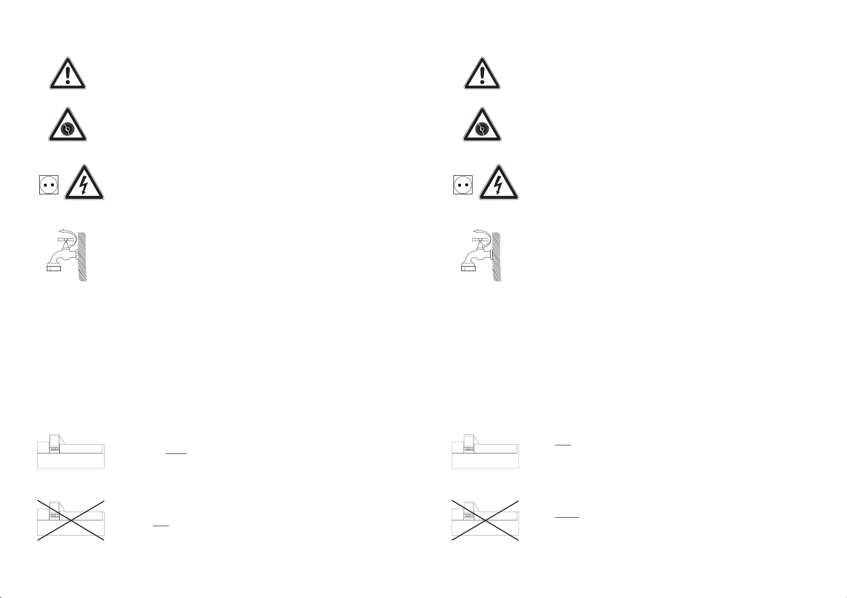
= Attention, important to observe.
= Sicherheit, unbedingt beachten!
Note =
Warning =
= Danger of mechanical damage of the machine!
= Danger of electrical schock!
= Close water tap when not working with the processor
Additional information regarding use or functionality
Pay careful attention to these comments!
Hinweis =
Achtung =
= Mechanische Beschädigung der Maschine möglich!
= Gefahr durch elektrischen Schlag!
= Nach Arbeitsende Wasserzuleitung schließen!
Wichtige Information für die Entwicklung oder die
Maschinenfunktion!
Unbedingt beachten, sonst Fehlfunktion!
2200
2200
= Applies only to the indicated!
= Does not apply to the indicated!
= Gilt nur für dieses Modell!
2200
= Gilt nicht für dieses Modell!
2200
2
Page 3

CHAPTER P AGE
KAPITEL SEITE
TECHNICAL DATA
1. UNPACKING THE UNIT 7
1.1 Removing the packaging material and processor 7
1.2 Shipping damage 7
1.3 Keep the packaging material 7
2. SCOPE OF DELIVERY 8
3. PREPARING FOR INSTALLATION 8
3.1 Installation site 8
3.2 Electrical needs 9
3.3 Water pressure 9
3.4 Water temperature 10
3.5 Drain needs 10
3.6 Room temperature 10
4. INSTALLATION INSTRUCTIONS 11
4.1 Chemical reclamation 11
4.2 Drain connection 11
4.3 Connection to the drinking water supply 12
4.4 Connecting the refill lines 12
4.5 Connecting the rinse-water lines 13
4.6 Electrical connection 13
4.6.1 Battery back-up connection 14
4.7 Installation check list 14
6
TECHNISCHE DATEN
6
1. AUSPACKEN 7
1.1 Entfernen des Kartons 7
1.2 Transportschäden 7
1.3 Verpackung 7
2. LIEFERUMFANG 8
3. INSTALLATIONSVORBEREITUNG 8
3.1 Standort 8
3.2 Stromversorgung 9
3.3 Wasserdruck 9
3.4 Wassertemperatur 10
3.5 Abwasser 10
3.6 Raumtemperatur 10
4. INSTALLATIONSANLEITUNG 11
4.1 Chemikalienauffangvorrichtung 11
4.2 Abwasseranschluß 11
4.3 Anschluß an das Trinkwassernetz 12
4.4 Anschluß der Nachfüllschläuche 12
4.5 Wasseranschluß 13
4.6 Elektrischer Anschluß 13
4.6.1 Notstromversorgung 14
4.7 Installationscheckliste 14
5. PREPARING TO PROCESS 15
5.1 First things first 15
5.2 Filling the water-bath 15
5.3 Setting the tempered water supply 15
5.4 Filling the chemical bottles 16
5.5 Filling the rear storage bottles 16
5.6 Setting the tank system plug 17
5.7 Setting the roller supports 17
5.8 Automatic cooling 18
5.9 Collecting used chemicals 18
5. VORBEREITUNG ZUR INBETRIEBNAHME 15
5.1 Zu Beginn 15
5.2 Füllen des Wassermantelbades 15
5.3 Einstellung des temperierten Wasserzulaufes 15
5.4 Füllen der Chemikalienflaschen 16
5.5 Einstellen des Wasserspiegels 16
5.6 Tank System Anpassung 17
5.7 Rollenbockeinstellung 17
5.8 Automatische Kühlung 18
5.9 Auffangen gebrauchter Chemikalien 18
3
Page 4

CHAPTER PAGE
KAPITEL SEITE
6. PROGRAMMING 20
6.1 General information about programming 20
6.1.1 SET mode 20
6.2 Programming 21
6.2.1 Altering process data 21
6.2.2 Raising and lowering the lift arm manually 22
6.2.3 Heat exchanger 22
6.2.4 Automatic refill 23
6.2.5 Rinsing option 23
6.2.6 Setting the rinse water temperature 24
6.2.7 Quick tempering feature 25
6.2.8 Option 25
6.2.9 Standby-Temp. 38°C 26
6.2.10 Changing the security code number 26
6.2.11 Setting the language 26
6.2.12 Adjusting the panel illumination 27
6.2.13 Cursor 27
6.2.14 Display of processing errors 27
6.2.15 Abort 27
7. STARTING A PROCESS 28
7.1 Selecting the correct process 28
7.2 Selecting the chemical volume needed 28
7.3 Selecting the rotation speed 2 9
7.4 Adjusting the remaining chemical volume 29
7.5 Final check list 30
7.6 Starting a process 30
7.7 At the end of a process 32
6. PROGRAMMIERUNG
20
20
6.1 Wissenswertes zur Programmierung 20
6.1.1 Der SET-Mode 20
6.2 Die Programmierung 21
6.2.1 Prozeßdaten ändern 21
6.2.2 Hebearm manuell 22
6.2.3 Wärmetauscher 22
6.2.4 Automatische Nachfüllung 23
6.2.5 Wässerungs-Option 23
6.2.6 Einstellen der Waschwassertemperatur 24
6.2.7 Schnelltemperierung 25
6.2.8 Option 25
6.2.9 Standby-Temp. 38°C 26
6.2.10 Code-Nummer ändern 26
6.2.11 Sprache: *D* 26
6.2.12 LCD-Beleuchtung 27
6.2.13 Cursor 27
6.2.14 Fehlerliste 27
6.2.15 Abbrechen 27
7. STARTEN EINES PROZESSES 28
7.1 Wählen des Prozesses 28
7.2 Wahl der Fördermenge 28
7.3 Wahl der Rotationsgeschwindigkeit 29
7.4 Restmenge 29
7.5 Endgültige Checkliste 30
7.6 Starten des Prozesses 30
7.7 Nach Prozeßende 32
8. SPECIAL FUNCTIONS 32
8.1 Reading the Actual temperatures 32
8.2 Overriding the temperature check 3 3
8.3 Automatic Temperature Compensation (ATC) 34
8.3.1 Defining ATC 34
8.3.2 Mounting the B/W bottle rack 34
8.3.3 Selecting the program 34
8.3.3.1 Background temperature 34
8.3.4 Explanation of the ATC range 35
9. TROUBLESHOOTING 36
8. BESONDERE FUNKTIONEN 32
8.1 Ablesen der IST-Temperaturen 32
8.2 Überspringen der Temperaturkontrolle 33
8.3 ATC-Automatische Temperatur Compensation 34
8.3.1 Was ist ATC? 34
8.3.2 Mechanische Umbauten 34
8.3.3 Programm einstellen 34
8.3.3.1 Hintergrund-Temperatur 34
8.3.4 Arbeitsweise des Programms 35
9. STÖRUNGSSUCHE UND -BEHEBUNG 36
4
Page 5

CHAPTER PAGE
KAPITEL SEITE
10. SPECIAL PROCESSING INSTRUCTIONS 36
10.1 Introduction to the developing process 36
10.2 E-6 processing 36
10.3 B/W processing 36
10.4 Factory default settings 37
11. CLEANING AND MAINTENANCE 40
11.1 Clean-up at the end of the process 40
11.2 The Cleaning programmes 4 0
11.3 Lubrication of the lift arm 40
11.4 Cleaning the processor 41
11.5 Drive gears 41
11.6 Algae prevention 42
11.7 Removing the bottles 42
11.8 Prolonged periods of inoperation 42
11.9 Storing the processor below freezing 42
11.10 A note on the filling levels 42
11.11 Cleaning of the air filter 42
12. AFTER-SALES SERVICE 43
12.1 Before contacting the after-sales service 43
10. BESONDERE VERARBEITUNGSHINWEISE 36
10.1 Einführung zur Entwicklung 3 6
10.2 E-6 Verarbeitung 36
10.3 S/W Verarbeitung 36
10.4 Werkseitige Belegung der Programme 37
11. REINIGUNG UND WARTUNG 40
11.1 Reinigung bei Prozeßwechsel 40
11.2 Reinigungsprogramme 40
11.3 Schmierung 40
11.4 Reinigung des Gerätes 41
11.5 Antriebsritzel 41
11.6 Verhinderung von Algenbildung 42
11.7 Entnehmen der Flaschen 42
11.8 Langzeit-Nichtbenutzung 42
11.9 Lagerung bei Minustemperaturen 42
11.10 Anmerkungen zu den Füllmengen 42
11.11 Reinigung des Luftfilters 42
12. SERVICE 43
12.1 Bevor Sie den Service kontakten 43
13. WARRANTY 44
14. LEGEND 45
13. GARANTIE 44
14. LEGENDE 45
5
Page 6

TECHNICAL DATA
TECHNISCHE DATEN
ATL-2400 / 2500 ATL-2200 / 2300
Height 122 cm (48") 61 cm (24")
Height with largest
drum in drainage position 177 cm (69") 116 cm (45")
Depth 51 cm (20") 51 cm (20")
Width 117 cm (46") 117 cm (46")
Weight (empty) 100 kg (223 lbs) 35 kg (78 lbs)
Min. water pressure 1 bar 1 bar (15 p.s.i.)
Max. water pressure 6 bar 6 bar (90 p.s.i.)
Approx. capacity of water-jacket 16 L (4¼ ga) 16 L (4¼ ga)
Range of process temperature 20 - 40°C (28,8 - 97,6°F)
Allowable range of temperature in working area: 15 - 28°C (36,6 - 68,3°F)
Power ratings (in kW):
230 V 50/60 Hz 115 V 50/60 Hz
ATL-2200 1,3 0,9
ATL-2300 1,3 0,9
ATL-2400 1,3 0,9
ATL-2500 1,3 0,9
ATL-2400 / 2500 ATL-2200 / 2300
Höhe 122 cm (48") 61 cm (24")
Höhe mit größter
Trommel in Entleerstellung 177 cm (69") 116 cm (45")
Tiefe 51 cm (20") 51 cm (20")
Breite 117 cm (46") 117 cm (46")
Gewicht (leer) 100 kg (223 lbs) 35 kg (78 lbs)
Min. Wasserdruck 1 bar 1 bar (15 p.s.i.)
Max. Wasserdruck 6 bar 6 bar (90 p.s.i.)
Wassermantelbadkapazität ca. 16 L (4¼ ga) 16 L (4¼ ga)
Prozeß-Temperaturbereich 20 - 40°C (48,8 - 97,6°F)
Umgebungs-Temperaturbereich 15 - 28°C (36,6 - 68,3°F)
Leistung (alle Angaben in KW):
230 V 50/60 Hz 115 V 50/60 Hz
ATL-2200 1,3 0,9
ATL-2300 1,3 0,9
ATL-2400 1,3 0,9
ATL-2500 1,3 0,9
Voltage tolerance: 230 V ± 10 %
115 V ± 10 %
Spannungstoleranz: 230 V ± 10 %
115 V ± 10 %
6
Page 7

1. UNPA CKING THE UNIT
1. AUSPACKEN
1.1 Removing the packaging material and processor
The unit is delivered in a cardboard box (total weight approx. 37 kgs/82 lbs) with additional packaging.
To make unpacking and installation easier, it's necessary to have someone help. Cut the tape on the top of
the box and open it. Remove the upper support of corrugated cardboard and the styrofoam packaging (see
drawing below). With 1 person at each end of the box, carefully lift the processor out.
1.1 Entfernen des Kartons
Das Gerät wird in einem Karton geliefert (Gesamtgewicht ca. 40 kg) (89 lbs). Zum Auspacken des ATL sind
2 Personen erforderlich. Sie schneiden das obere Klebeband durch und klappen den Karton auf. Entfernen Sie
die obere Stütze aus Wellkarton und die Schaumstoffpolster (siehe Zeichnung unten). Heben Sie, mit je
einer Person an den Enden des Kartons, den Processor vorsichtig aus dem Karton heraus.
1.2 Shipping damage
Make sure to check for any concealed shipping damage at this point. In the event your processor has
suffered any damage, contact the freight company or your local dealer immediately. It is important to file
any such claims immediately.
1.3 Keep the packaging material
Do not throw out the packaging materials. To ensure safe transportation for any repairs by our service
department which may be necessary, please use only the original box with the inserts and pack the unit as shown
in the illustrations above. We accept no responsibility for any damage which may occur as a result of incorrect
packing.
1.2 Transportschäden
Prüfen Sie das Gerät auf etwaige Schäden und benachrichtigen Sie gegebenenfalls, umgehend die Spedition,
die das Gerät geliefert hat oder den Händler, von dem Sie das Gerät bezogen haben.
1.3 Verpackung
Um einen sicheren Transport bei eventuellen Servicereparaturen zu gewährleisten, verwenden Sie bitte nur
den Originalkarton mit den Einlagen und verpacken Sie das Gerät gemäß obenstehender Abbildungen. Für
Schäden, die durch unsachgemäße Verpackung entstehen, kann keine Haftung übernommen werden.
7
Page 8

2. SCOPE OF DELIVERY
2. LIEFERUMFANG
Article name Item No. Quantity
ATL 2200 2300 2400 2500
Scaled bottle, white without lid 05013 6 6 6 6
Scaled bottle, white 3373 6 - - Processor-Clean 4181 1 1 1 1
Accessory Kit 93024 1 1 1 1
Drainage Kit 92314 1 1 1 1
Chemical Reclamation Cart 95564 - - 1 1
Bench support 95563 - - 1 1
Mains cable according to country 1 1 1 1
Operating instruction according to country 1 1 1 1
15-litre canisters with lid and 3387 - - 6 6
floating lid
15-litre canisters without lid and - - 6 6
floating lid
Bottle with hole, black ø 7,5 05091 - - 6 6
3. PREPARING FOR INSTALLATION
3.1 Installation site
It is not necessary to install the ATL in a darkroom, it was designed for daylight operation. All JOBO tanks
and drums are light-tight when used properly.
The ATL should be installed near a suitable drain, a cold water source (and hot water source if required,) and an
appropriate power source.
2200/2300
The ATL should be installed on a level base with a load bearing capacity of at least 68 kg (150 lbs). The surface
should be water-proof. Also, it must be higher than the drain water installation for the processor.
maximum height
wall
Artikelbezeichnung Artikel Nr. Menge
ATL 2200 2300 2400 2500
Skalenflasche weiß ohne Deckel 05013 6 6 6 6
Skalenflasche weiß 3373 6 - - Processor-Clean 4181 1 1 1 1
Zubehörpaket 93024 1 1 1 1
Abflußgarnitur 92314 1 1 1 1
Kanisterwagen 95564 - - 1 1
Gestell 95563 - - 1 1
Netzkabel je nach Land 1 1 1 1
Bedienungsanleitung je nach Land 1 1 1 1
15 Liter Kanister mit Deckel und 3387 - - 6 6
Schwimmdeckel
15 Liter Kanister ohne Deckel und - - 6 6
Schwimmdeckel
Durchlaufflasche schwarz ø 7,5 05091 - - 6 6
3. INSTALLATIONSVORBEREITUNG
3.1 Standort
Das ATL muß nicht in einer Dunkelkammer installiert werden, da alle JOBO Tanks und Trommeln lichtdicht sind.
Das ATL sollte in der Nähe einer ausreichenden Abwassereinrichtung, Kaltwasseranschluß und ggf.
Warmwasseranschluß sowie eines Stromanschlußes installiert werden.
Das ATL sollte auf einer ebenen Stellfläche mit einer Tragfähigkeit von mindestens 68 kg (150 lbs) installiert
2200/2300
werden. Die Stellfläche sollte wasserfest sein. Ebenfalls muß sie höher liegen, als die Abwassereinrichtung für
den Processor.
maximale Höhe
Mauer
10 cm
51 cm
61 cm
116 cm
117 cm
mains lead
length:
200 cm
Netzkabel
Länge:
200 cm
10 cm
51 cm
61 cm
116 cm
117 cm
8
Page 9

The ATL should be installed on a level base with a load bearing capacity of at least 250 kg per m² . Failure to
do so will cause processing problems due to uneven wetting of the film or paper. The surface , or the floor, should
be waterproof. uneven surfaces can be compensated using the leveling feet. For this purpose, use the enclosed
spanner to turn the leveling feet to the required position so that the ATL is level.
3.2 Electrical needs
Das ATL sollte auf einer ebenen und waagerechten Stellfläche mit einer Tragfähigkeit von mindestens 250 kg
pro m² installiert werden, dies verhindert Entwicklungsfehler durch ungleichmäßige Benetzung.
2400/25002400/2500
Die Stellfläche bzw. der Fußboden sollte wasserfest sein. Unebenheiten können ggf. durch die höhenverstellbaren Füße ausgeglichen werden. Drehen Sie dazu mit dem im Beipack befindlichen Maulschlüssel die Stellfüße
auf die erforderliche Position, damit das ATL in der Waage steht.
An earthed mains connection point is required. It is recommendable to consult a local electrician. Please note that
the unit may only be connected to a socket equipped with an earthing contact. We strongly recommend to insert
a GFCI outlet. The length of the mains lead is approximately 1,80 m (6'). Ensure that an adequately fused circuit
is located within 1,80 m (6') of the installation point for your ATL. When using an extension lead, observe that
this has to have at least a diametre of 1,5 mm².
Note the information on the nameplate of the ATL.
3.3 Water pressure
A water pressure of between 1 and 6 bar (15 and 90 p.s.i.) is required in order to operate the processor.
A pressure level of less than 1 bar may result in unusually long filling times and insufficient rinsing.
Pressure greater than 6 bar may damage the processor. When water pressure above 6 bar pply, we recommend
installing the pressure reducer, (Item no. 4177), up-line.
Warning: To avoid the possibility of damage caused by water from leaking
tubes, the water taps should be readily accessible and turned off when
the processor is not being used!
3.2 Stromversorgung
Es wird ein geerdeter Stromanschluß benötigt. Nehmen Sie am besten Verbindung mit einem Elektriker vor
Ort auf. Achten Sie darauf, daß das Gerät nur an eine Steckdose mit Schutzkontakt angeschlossen werden
darf. Das Zwischenschalten eines FI-Schalters wird dringend empfohlen. Die Länge des Stromanschlußkabels
beträgt ungefähr 2,00 m. Stellen Sie sicher, daß sich eine ausreichend abgesicherte Steckdose innerhalb von
1,80 m (6 ft.) vom Standort Ihres ATL's befindet. Bei der Verwendung eines Verlängerungskabels muß dieses mit
einem Querschnitt von min. 1,5 mm² ausgelegt sein.
Beachten Sie die Angaben auf dem Typenschild des ATL's.
3.3 Wasserdruck
Ein Wasserdruck zwischen 1 und 6 bar (15 und 90 p.s.i.) ist notwendig, um den Processor zu betreiben. Ein Druck
von weniger als 1 bar kann eine ungewöhnlich lange Einfüllzeit für das Wassermantelbad oder ungenügende
Wässerungen zur Folge haben Wasserdruck von mehr als 6 bar kann Schaden am Processor verursachen. Bei
einem Wasserdruck über 6 bar empfehlen wir, den Druckminderer Art. Nr. 4177 vorzuschalten.
Warnung: Um die Möglichkeit von Wasserschäden durch undichte
Schläuche zu vermeiden, sollten sich die Wasserhähne in
Reichweite befinden. Diese stets schließen, wenn der
Prozessor nicht in Gebrauch ist!
9
Page 10

3.4 Water temperature
3.4 Wassertemperatur
The newATL requires one cold and one warm water hook up each. The tempered water supply should be set
exactly to the developing temperature. If there is no warm water supply, we recommend the warm water
pressure tank with special mixing tap (Item no. 4167). The cold water connection serves for filling the waterjacket and at the same time for cooling the ATL.
If processes are run that are below the ambient room temperature (e.g. 20°C for B/W), the temperature of the
supplied water must be lower than the lowest developing temperature of the process. If the temperature of the
supplied water is too high, the water can be cooled using an external cooling device. Ask your photo dealer or
JOBO for further information.
3.5 Drain needs
The ATL has two separate drains; one for the water jacket another for the chemical reclamation area.
(see illustration in Section 4.2)
The ATL 2200/2300 can be installed on a plate or on the specially designed support table from JOBO
(Item no. 4221). In each case both outlets must be connected to a drain water installation, which is lower than
the processor. For this purpose please use the hoses included in the scope of supply.
3.6 Room temperature
As the processor continuously maintains the temperatures of the water-jacket bath within the permitted limit,
normal fluctuations in the room between 15-28°C (59-83°F) will have no effect on exact tempering of the water.
Even so, JOBO recommends that the processor is not installed directly in the path of a heating or airconditioning vent.
In order to secure a perfect process temperature, always keep the rear bottles covered.
Das ATL benötigt je einen Kalt- und einen Warmwasseranschluß. Der temperierte Wasseranschluß sollte
genau auf die Entwicklungstemperatur eingestellt werden. Wenn keine temperierte Wasserversorgung zur
Verfügung steht, empfehlen wir den Warmwasserdruckspeicher mit Spezialmischbatterie Art. Nr. 4167.
Der Kaltwasseranschluß dient zur Füllung des Wassermantelbades und gleichzeitig zur Kühlung des ATL's.
Falls Prozesse gefahren werden, die unter der Umgebungstemperatur des Raumes liegen (z.B. 20°C für S/W),
so muß die Temperatur des zugeführten Wassers niedriger sein als die niedrigste Entwicklungstemperatur des
Prozesses. Falls die Temperatur des zugeführten Wassers zu hoch ist, kann das Wasser mit einer externen
Kühlvorrichtung gekühlt werden. Fragen Sie Ihren Fotohändler oder JOBO nach weiteren Informationen.
3.5 Abwasser
Das ATL hat zwei separate Abflußöffnungen; einen Wassermantelbadabfluß und einen gemeinsamen
Wasserablaßanschluß für Wässerung und Überlauf des Wassermantelbades.
(Siehe Illustration in Abschnitt 4.2)
Das ATL-2200/2300 kann auf einer Platte oder auf den besonders dafür entworfenen Arbeitstisch von JOBO
(Art. Nr. 4221) gestellt werden. In jedem Fall müssen beide Ablaßanschlüsse an eine Abwassereinrichtung
angeschlossen werden, die tiefer als der Processor liegt. Dazu benutzen Sie bitte die im Lieferumfang
enthaltenen Schläuche.
3.6 Raumtemperatur
Da der Processor ständig die Temperaturen des Wassermantelbades innerhalb der zugelassenen Grenze
konstant hält, wird eine normale Schwankung der Raumtemperatur von 15-28°C die exakte Temperierung
nicht beeinflussen. Es wird trotzdem empfohlen, den Processor nicht in der unmittelbaren Nähe von
Klimaanlagen oder Heizkörpern zu installieren.
Für eine gute Temperierung die hintere Flaschenabdeckung stets schließen.
10
Page 11

4. INSTALLATION INSTRUCTIONS
4. INSTALLATIONSANLEITUNG
4.1 Chemical reclamation
The ATL collects used chemicals in bottles or 15-litre canisters.
Bench support
(Item No. 4221)
for ATL 2200/
2300
Option
4.2 Drain connection
On the back of the ATL, there are two drain connections, the water bath (A) on the left and the chemical
collection/rinse (B) on the right (connections are illustrated below).
ATL 2200/2300
Chemical
reclamation cart
(Item No. 4225)
for ATL 2200/2300
Option
ATL 2400/
2500
4.1 Chemikalienauffangvorrichtung
Das ATL fängt die verbrauchten Chemikalien in Flaschen oder 15 Liter Kanistern auf.
ATL 2200/2300
ATL 2400/
2500
Arbeitstisch
(Art. Nr. 4221)
für ATL 2200/
2300
Option
Chemikalienauffangwagen
(Art. Nr. 4225)
für ATL 2200/2300
Option
4.2 Abwasseranschluß
An der Rückseite des ATL's befinden sich zwei Abwasseranschlüsse.
Der Hauptwannenabfluß (A) auf der linken Seite und der Überlauf/- Wässerungswasseranschluß (B) auf der
rechten Seite. (Siehe untenstehende Zeichnung.)
B
A
If the ATL is placed on a plate, both drain water outlets must be led to a suitable drain with hoses. To install
the hoses (1/2" PVC hose = water bath, 1" hose = reclamation area drain) push one end of the thinner hose on
connector A, then push the thicker hose onto connector B. Both hoses can then be joined to the connecting
element.
B
A
Falls das ATL auf eine Platte gestellt wird, müssen beide Abwasseranschlüsse mit Schläuchen in einen dafür
geeignetten Abfluß geleitet werden. Zum Installieren der Schläuche (1/2" PVC Schlauch = Hauptwannenanschluß, 1" Schlauch = Überlaufanschluß) schieben Sie ein Ende des dünneren Schlauches über den Anschluß A.
Schieben Sie den dickeren Schlauch über den Anschluß B. Beide Schläuche können mit dem Verbindungsstück
verbunden werden.
11
Page 12

4.3 Connection to the drinking water supply
4.3 Anschluß an das Trinkwassernetz
In order to meet these regulations, the ATL’s must have an overflow system to prevent the water level in the
machine from rising above a certain level in the case of a blocked drain line. In a case where a drain line was
blocked, water could escape from this overflow point.
To insure proper operation of the processor, do not use demineralized or deionized water.
4.4 Connecting the refill lines
2400/2500
End piece
Zur Einhaltung der Vorschriften ist an der Geräterückseite ein Überlauf angebracht, der bei verstopftem
Abfluß den maximalen Wasserspiegel im Gerät begrenzt. Bei verstopftem Abfluß könnte hier also Wasser
austreten!
Kein destilliertes oder entmineralisiertes wasser verwenden.
4.4 Anschluß der Nachfüllschläuche
2400/2500
Lanze
The refill hoses (models 2400/2500 only) need to be inserted in the 15-liter bottles stored below the processor.
The hard-plastic end goes into the hold on the top of the bottle.
It is important to watch the correct numbering of the hoses. Their numbers must corrolate with the position
numbers of the 15-litre canisters otherwise faulty developments will occur.
Bei den Geräten ATL 2400 und ATL 2500 werden die Nachfüllschläuche mit der Lanze in die Kanister gesteckt.
Unbedingt auf die richtige Nummerierung achten, da es sonst zu Fehlentwicklungen kommen kann.
12
Page 13

4.5 Connecting the rinse water lines
4.5 Wasseranschluß
The ATL requires two rinse water connections with 3/4" standard thread.
When you look at the rear panel of the unit, you will see the connection point indicated with a red dot, which
is connected to the tempered hot water supply, and the connection point indicated with a blue dot, which is
connected to the cold water supply.
Set the tempered water supply to the developing temperature.
When connecting the supply tubes, please ensure that the valve threads are in perfect condition. Screw the nuts
tight, but do not strip the thread, as this may cause damage to the thread. The water supply pressure must be between
1 and 6. Water pressures below 1 bar may result in inadequate washing, and water pressures over 6 bar may damage
the ATL. If necessary, use a pressure reducer (Item no. 4177).
Note: When using water which contains particle matter, we recommend installation of a water filter
Item Mo. 8050, in order to prevent damage and deposits on the film.
4.6 Electrical connection
An earthed, adequately fused electric power supply is required. Please note the technical data at the beginning
of these operating instructions.
Important safety information
Warning: The electrical connection and the earthing must be installed in the
correct manner, in order to avoid any unnecessary risk of fire, electric
shock, or personal injury. The owner of the processor assumes full
responsibility for ensuring the electrical connection is sufficiently safe.
Your processor must be connected to a properly functioning earthing
system, in order to reduce the risk of electric shock in the event of a
malfunction or defect. In addition, we strongly recommend to connect
the processor to a GFCI (ground fault interrupter circuit).
The processor is equipped with a mains lead incorporating a protective conductor and a plug with an earthing
contact. Insert the mains plug in a socket which has been duly installed and earthed.
Under no circumstances is the plug of the mains lead to be changed. If the suppliedmains plug does not fit
into the socket, an authorised electrician is to be called in to install a suitable socket.
In order to prevent condensation in the electronics, the fan will operate for 3 hours after turning off the processor.
Das ATL benötigt zwei Wasseranschlüsse mit 3/4" Standard Gewinde. Wenn Sie auf die Rückseite des
Gerätes sehen, wird der mit einem roten Punkt gekennzeichnete Anschluß, mit dem temperierten
Warmwasseranschluß, der mit einem blauen Punkt gekennzeichnete Anschluß mit dem Kaltwasseranschluß
verbunden. Stellen Sie den temperierten Warmwasseranschluß auf die Entwicklungstemperatur ein.
Werden die Verbindungsschläuche angeschlossen, so achten Sie bitte darauf, daß die entilgewinde
einwandfrei sind. Drehen Sie die Muttern fest an, aber überdrehen Sie die Verbindung nicht, da sonst die
Gewinde beschädigt werden können. Der Druck der Wasserzufuhr muß zwischen 1 bis 6 bar liegen.
Wasserdruck unter 1 bar kann ungenügende Wässerung zur Folge haben und Wasserdruck über 6 bar kann
das ATL beschädigen. Falls notwendig, verwenden Sie einen Druckminderer (Art. Nr. 4177).
Hinweis: Bei partikelhaltigem Wasser empfehlen wir die Installation
eines Wasserfilters Art. Nr. 8050, um eine Beschädigung und
Rückstände auf den Filmen zu vermeiden.
4.6 Elektrischer Anschluß
Ein geerdeter, genügend abgesicherter Stromanschluß ist erforderlich. Beachten Sie die technischen Daten zu
Beginn dieser Bedienungsanleitung.
Wichtige Sicherheitshinweise
Warnung: Um ein unnötiges Risiko von Feuer, elektrischem Schock oder
persönlicher Verletzung zu verhindern, müssen der elektrische
Anschluß und die Erdung ordnungsgemäß installiert werden.
Es ist die persönliche Verantwortung des Processor-Eigentümers,
für ausreichende Sicherheit der Stromzufuhr zu sorgen. Ihr
Processor muß an eine ordnungsgemäße Erdung angeschlossen
werden, um im Fall einer Betriebsstörung oder eines Gerätedefektes das Risiko eines elektrischen Schlages zu reduzieren.
Darüber hinaus empfehlen wir dringend die Verwendung eines
Fehlerstrom-Schutzschalters (FI-Schalter).
Der Processor ist mit einem Anschlußkabel ausgerüstet, das einen Schutzleiter und einen Stecker mit Schutzkontakt besitzt. Stecken Sie den Netzstecker in eine Steckdose, die ordnungsgemäß installiert und geerdet ist.
Verändern Sie unter keinen Umständen den Stecker des Netzkabels. Wenn der mitgelieferte Netzstecker nicht
in die Steckdose paßt, lassen Sie eine geeignete von einem autorisierten Elektriker installieren.
Um Kondensatbildung in der Elektronik zu vermeiden, läuft der Lüfter nach dem Ausschalten drei Stunden nach.
Name plate
Main circuit connection
Fuse T 6,3A (230V) / T 10A (115V)
Internal supply heating element
Internal supply monitoring
If desired, a back-up system can be integrated.
Typenschild
Netzanschluß mit passender Kaltgeräte-Anschlußleitung
Sicherung T 6,3A (230V) / T 10A (115V)
interne Versorgung Heizung
interne Versorgung Steuerung
Hier kann gegebenenfalls ein Back-Up-System eingeschleift werden.
13
Page 14

4.6.1 Battery back-up connection
4.6.1 Notstromversorgung
Your ATL is designed for use with an optional battery back-up unit. For more information either contact
JOBO Labortechnik or send an order for the battery back-up, Item No. 4267 (230 Volts) / Item No. 4268
(115 Volts).
4.7 Installation check list
· Is the processor properly leveled?
· Are the drain connection finished?
· Is the water supply available and not leaking?
· Is the processor connected to a correctly installed socket?
Ihr ATL ist serienmäßig für den Anschluß einer Notstromversorgung (Batterie-Back-Up) vorbereitet. Für weitere
Informationen wenden Sie sich bitte an JOBO-Labortechnik oder bestellen Sie das Batterie-Back-Up unter der
Art. Nr. 4267 (230 V) / Art. Nr. 4268 (115 V).
4.7 Installations Checkliste
· Der Processor ist mit der Wasserwaage ausgerichtet worden.
· Abwasseranschlüsse sind verbunden und verlegt.
· Der Wasseranschluß ist geöffnet und auf undichte Stellen am Wasserhahn und am Gerät geprüft worden.
· Der Processor ist an eine korrekt installierte Steckdose angeschlossen.
14
Page 15

5. PREP ARING T O PROCESS
5. VORBEREITUNG ZUR INBETRIEBNAHME
Four different languages are available for the display. First select the desired language, under SET mode (section
6.2.11), option 10.
5.1 First things first
... turn on the cold water supply and the tempered water supply (if installed 6.2.6).
5.2 Filling the water-bath
Turn the processor on, using the on/off switch (5).
The unit will automatically start filling after a few minutes and will maintain the correct water level.
Die Anzeige kann vier verschiedene Sprachen anzeigen. Wählen Sie als erstes wie unter SET-Mode Punkt
6.2.11 unter Punkt 10 die gewünschte Landessprache.
5.1 Zu Beginn
Drehen Sie den Kaltwasserzulauf und den temperierten Wasserzulauf (falls vorhanden 6.2.6) auf.
5.2 Füllen des Wassermantelbades
Schalten Sie das ATL mit dem Netzschalter (5) ein.
5
5
Das Gerät beginnt nach wenigen Sekunden, automatisch das Wassermantelbad zu füllen und hält den richtigen
Wasserspiegel.
5.3 Setting the tempered water supply
The temperature of the warm water must be adjusted with an external mixing tap and a thermometer. (If not
available, please use the warm water pressure container with mixing tap, specially offered for this purpose under
(Item no. 4167, see 6.2.6).
Turn on the cold water supply and the tempered water supply (if installed 6.2.6).
5.3 Einstellung der Wassertemperatur
Die Temperatur des warmen Wassers muß mit einem externen Mischventil und Thermometer eingestellt
werden (falls nicht vorhanden, verwenden Sie bitte den speziell für diese Anwendung angebotenen
Warmwasserdruckspeicher mit Mischventil Art. Nr. 4167, siehe 6.2.6).
Drehen Sie den Kaltwasserzulauf und den temperierten Wasserzulauf (falls vorhanden 6.2.6) auf.
15
Page 16

5.4 Filling the chemical bottles
5.4 Füllen der Chemikalienflaschen
Unscrew the bottle caps and pour the required quantity of chemicals into the bottles. The maximum
capacity of the bottles is 1 litre.
max. 1000 ml
max. 1000 ml for models
ATL-2200 / 2300 / 2400
max.1500 ml for model
ATL-2500
The quantity poured into the bottles will then be entered into the processor as explained in section 7.2.
The bottle caps are placed back on the bottles and screwed tight. Inadequate tightening will result in
developing errors. Ensure that the tubes leading to each bottle are correctly inserted.
Note: Do not overfill the bottles. If this is done it is possible chemicals might
siphon up the air compression lines and damage the processor.
Also, never use the electronic head of your processor as a place to store
any liquids. An accidental spill could result in damage to the processor.
To insure proper operation of the processor, do not use demineralized or deionized water.
5.5 Filling the rear storage bottles
The ATL-2200 has six 1-litre bottles in the rear of the processor that are used for pre-tempering. To fill the bottles
remove the rear bottle cover and lift them out. Before filling the bottles, mark them with a grease pen.
To take the bottles out, first lift the back cover and place it in the support. Mark the bottles with a grease pen
processor and replace the bottle cover. It is important to close the bottle cover to insure accurate tempering of the
2200
solutions.
2200/2300
and then fill the 1-litre-bottles with the chemicals you want to pre-heat. Put the filled bottles back into the
Automatic refilling
The ATLs come prepared for automatic refilling (ATL-2400 rear-, ATL-2500 front bottles). The refill pumps start
working, if a programme is selected, which activates those bottles with automatic refilling. The max. working time
of the pump is choosed in such way assuring a secure refilling of the bottles. If there is no solution left in the 15litre tanks or should the hose in the pump be leaking, the refilling procedure cannot be accomplished in the
determined time. In such a case an error message is shown in the display and the buzzer starts beeping. Correct
the error and follow the indications in the display read-out.
If desired, the automatic refilling can also be switched off. Select option 3 in the SET mode. The bottle battery
works now for manual refilling.
Schrauben Sie die Flaschenverschlüsse ab und füllen die Flaschen mit der gewünschten Chemikalienmenge.
Die maximale Füllmenge beträgt 1 Liter.
Die eingefüllte Menge wird gemäß der Anleitung in Abschnitt 7.2 eingestellt.
Die Flaschenverschlüsse werden wieder auf die Flaschen gesetzt und fest verschraubt. Unzureichendes
Verschließen verursacht Entwicklungsfehler.
Achtung: Überfüllen Sie die Flaschen nicht, da sonst Chemikalien
durch die Luftschläuche ins Gerät eindringen können und
Langzeitschäden verursachen, sowie zu Chemikalienverschleppungen führen. Sie sollten den Elektronikkopf
nicht als Ablagefläche, zum Eingießen von Chemikalien
oder sonstiger Flüssigkeiten nutzen, da die Elektronik durch
eindringende Feuchtigkeit Schaden erleiden kann.
Kein destilliertes oder entmineralisiertes wasser verwenden.
5.5 Füllen der hinteren Vorratsflaschen
Das ATL-2200 beinhaltet sechs 1-Liter Flaschen zur Vorwärmung, die im Processor eingesetzt werden. Um die
Flaschen entnehmen zu können, heben Sie die hintere Abdeckung hoch. Kennzeichnen Sie die Flaschen vor dem
Füllen mit einem nicht wasserlöslichen Stift. Stellen Sie die gefüllten Flaschen zurück und legen Sie die
2200
2200/2300
Flaschenabdeckung wieder auf. Das Schließen der Flaschenabdeckung ist wichtig für die einwandfreie
Temperierung
Automatische Nachfüllung
Die automatische Nachfüllung (ATL-2400 hintere-, ATL-2500 vordere Flaschenbatterie) ist werkseitig
eingeschaltet. Wird ein Programm gewählt, das auf die autom. nachgefüllten Flaschen zugreift, so laufen die
Pumpen an. Die maximale Pumpenlaufzeit ist so gewählt, daß die Flaschen sicher gefüllt werden. Ist keine Chemie
mehr inden 15 Liter Kanistern oder der Schlauch in der Pumpe undicht, so können die Flaschen nicht in der
vorgegebenen Zeit aufgefüllt werden. Im Display wird eine Fehlermeldung angezeigt und der Buzzer
piept. Beheben Sie die Fehlerursache und folgen Sie der Displayanzeige.
Bei Bedarf kann die automatische Nachfüllung auch abgeschaltet werden. Wählen Sie den Punkt 3 im
SET-Mode. Die Flaschenbatterie arbeitet jetzt wie die manuell nachzufüllenden.
max. 1000 ml
Für ATL-2200 / 2300 / 2400
max. 1000 ml
Für ATL-2500
max.1500 ml
16
Page 17

5.6 Setting the tank system plug
JOBO offers a large number of tanks and drums, in order to meet every requirement. To enable all
these tanks and drums to be used, the coupling flange has two positions.
Appropriate adaption to the employed system is necessary.
The plug is pushed onto the connector which is not used. Make sure that the plug is fitted properly.
System 3000
Expert
Note: Exchange plug and
tube at a time.
5.6 Tank System Anpassung
JOBO produziert eine Vielzahl an Tanks und Trommeln, um allen Anforderungen entsprechen zu können.
Damit alle Tanks und Trommeln zum Einsatz kommen können, hat der Kupplungsflansch zwei Positionen.
Eine Anpassung an das jeweilige System ist erforderlich.
Der Stopfen wird auf den nicht verwendeten Anschluß gesteckt.
Stellen Sie sicher, daß der Stopfen richtig sitzt.
System 3000
Expert
Hinweis:
Stopfen und Rohr
jeweils tauschen.
Tube
Plug
5.7 Setting the roller supports
In view of the diversity of available tank and drum systems, the roller supports in the rotating tank require to
be adapted to the system employed. Slide the two black roller supports into the correct position (see drawing)
and use the two roller carriers in accordance with the employed tank system (facing inward or outward, or no
carriers). Rollers, roller supports and roller carriers are included in the supplied accessories.
System 1500 / 2500 / 2800
Rohr
System 1500 / 2500 / 2800
Stopfen
5.7 Rollenbockeinstellung
Wegen der Vielfalt der verfügbaren Tank- und Trommelsysteme sind die Rollenböcke in der Rotationswanne
jeweils anzupassen. Schieben Sie die beiden schwarzen Rollenböcke in die richtige Position (siehe
Zeichnung) und setzen Sie die beiden Rollenträger entsprechend dem verwendeten Tanksystem ein (nach
innen oder außen weisend, bzw. ohne Träger). Rollen, Rollenböcke und Rollenträger befinden sich im Zubehör.
17
Page 18

5.8 Automatic cooling
5.8 Automatische Kühlung
The water-jacket bath is cooled automatically until the correct developing temperature is reached. When the
water-jacket bath temperature rises higher than the selected developing temperature, the automatic cooling
system is activated. The cold water valve opens approx. 30 seconds after the temperature of the water-jacket
bath has risen above the selected temperature.
Note: If your cold water supply is not sufficiently cold to reduce the developing
temperature of the process, you may have to use a cooler. Please contact
your dealer or JOBO, should this be the case.
A useful tip: If you wish to switch from a high temperature, e.g. 38°C, to a low temperature, e.g. 20°C,
use the following procedure:
- Switch the unit (5) off.
- Open the drain valve (11) and hold the button down until the water-jacket bath is empty.
- Switch the unit on.
- Select the program with the new, lower temperature.
The jacket bath will begin to fill. This procedure will save considerable time and water.
5.9 Collecting used chemicals
The ATL 2200/2300 is designed so all chemicals are collected in 1-litre-bottles.
If the support table (Item no. 4221) is used together with the chemical reclamation cart (Item no. 4225), the
used chemicals can optionally also be led into the 15-litre-containers on the trolley.
2200/2300
ATL-2400 and 2500 additionally allow optional collection of chemicals in 15-litre containers.
Das Wassermantelbad wird automatisch gekühlt, bis die richtige Entwicklungstemperatur erreicht ist. Wenn die
Wassermantelbadtemperatur höher ist als die gewählte Entwicklungstemperatur, wird das automatische
Kühlsystem aktiviert. Das Kaltwasserventil öffnet etwa 30 Sekunden nachdem die Wassermantelbad temperatur über die gewählte Temperatur angestiegen ist.
Hinweis: Falls Ihr Kaltwasseranschluß nicht kalt genug ist, um die Entwick-
lungstemperatur des Prozesses zu senken, müssen Sie möglicherweise
einen Kühler einsetzen. Nehmen Sie diesbezüglich mit ihrem Händler
oder JOBO Kontakt auf.
Hilfreicher Tip: Falls Sie von einer hohen Temperatur, z.B. 38°C, zu einer niedrigen Temperatur,
- Schalten Sie das Gerät ab (5).
- Öffnen Sie das Ablaßventil (11), bis das Wassermantelbad leer ist.
- Schalten Sie das Gerät wieder ein.
- Wählen Sie das Programm mit der neuen, niedrigeren Temperatur.
Das Mantelbad beginnt sich zu füllen. Dieses Verfahren spart erheblich Zeit und Wasser.
z.B. 20°C, wechseln wollen, geschieht dies am schnellsten, wenn Sie das folgende
Verfahren anwenden:
5.9 Auffangen gebrauchter Chemikalien
Das ATL-2200/2300 ist so eingerichtet, daß alle Chemikalien in 1 Liter Flaschen
aufgefangen werden.
Falls der Unterschrank (Art. Nr. 4221) zusammen mit dem Chemikalienauffangwagen (Art. Nr. 4225) verwendet
2200/2300
wird, können die verbrauchten Chemikalien wahlweise auch in die 15 Liter Kanister auf dem Wagen abgeleitet
werden.
Das ATL-2400/2500 verfügt zusätzlich über die Möglichkeit die Chemikalien in
15 Liter Behältern aufzufangen.
For collection of the used chemicals in 15 litrecanisters, use the included hoses (see also illustration)
Zum Auffangen der gebrauchten Chemikalien in die 15
Liter Kanister werden die mitgelieferten Schläuche
(siehe Skizze) eingesetzt
18
Page 19

Note: Make sure to slide the chemical reclamation cart right up to the stop,
so the reclamation tubes line up with the openings of the bottles.
Used chemicals are reclaimed in the containers located at the left side of the cart (toward the control side). They
are collected in the same sequence as they are taken from the supply containers. Note that the chemicals from the
front and rear bottle batteries are collected together. If necessary, organise the processes in an appropriate order
to prevent chemicals from becoming mixed in the collecting containers.
Attention: Before starting a process, make sure there is sufficient room left in the
collecting containers, to prevent chemicals from entering into the
sewerage system as a result of overflowing collecting containers.
Should the filling quantity be greater than 1-liter, you cannot use the 1-liter collecting device.
Achtung: Chemikalienauffangwagen bis zum Anschlag einschieben, da
ansonsten die verbrauchte Chemie neben die Kanisteröffnung läuft.
Gebrauchte Chemikalien werden jetzt in der gleichen Reihenfolge, wie sie aus den Vorratsbehältern entnommen
werden, in den linken Kanistern aufgefangen. Beachten Sie, daß die Chemikalien aus der vorderen und hinteren
Flaschenbatterie gemeinsam aufgefangen werden. Ordnen Sie die Prozesse gegebenenfalls entsprechend, um
Vermischungen von Chemikalien in den Auffangbehältern zu vermeiden.
Achtung: Stellen Sie jeweils vor dem Starten eines Prozesses sicher,
daß die Kapazität der Auffangbehälter ausreichend ist, um
zu verhindern, daß Chemikalien durch überlaufende
Auffangbehälter in die Kanalisation gelangen.
Bei Füllmengen größer 1000 ml kann die 1L-Auffangvorrichtung nicht verwendet werden.
2500
2500
19
Page 20

6. PROGRAMMING
6. PROGRAMMIERUNG
Note: The numbers shown in parenthesis refer to the explanation in the
appendix of this manual.
6.1 General information about programming
Each AutoLab is pre-programmed for JOBO's recommended developing times for all common processes.
The pre-programmed processes are illustrated in Section 10.4. As the AutoLabs are user-programmable, the
programmes can, of course, be altered at any time. Should you wish to alter a programme, please refer to
Sections 6.1.1 to 6.2.1.
6.1.1 SET mode
Changes to programming are only possible while in SET mode. To enter SET mode, switch the processor on and
wait for it to perform the self-check. Press the ENTER key while holding down the F1 key.
NOTE:
Only when a code was assigned.
(see Section 6.2.10)
HINWEIS: Nummern in Klammern beziehen sich auf die Erklärung im
Anhang dieser Bedienungsanleitung.
6.1 Wissenswertes zur Programmierung
Wir haben jedes Programm Ihres ATL's mit unseren empfohlenen Entwicklungszeiten für verschiedene,
gängige Prozesse vorprogrammiert.
Die von uns eingespeicherten Prozesse sind in Kapitel 10.4. aufgeführt. Da das ATL bedienerprogrammierbar
ist, können die Programme natürlich jederzeit geändert werden. Lesen Sie die Abschnitte 6.1.1 bis 6.2.1, falls
Sie ein Programm ändern möchten.
6.1.1 Der SET-Mode
Die Änderung der Programmierung ist nur im SET-Mode möglich. Um in den SET-Mode zu gelangen, schalten
Sie das Gerät ein, warten das Ende des Selbsttestes ab. Halten Sie die F1-Taste gedrückt und betätigen Sie ENTER.
HINWEIS:
Nur wenn ein Code vergeben wurde!
(siehe 6.2.10)
The LCD display is altered to the following:
Press the arrow key (1) to scroll through the text:
4. Rinsing opt. 9. Alter code no.
5. Temp. of wash wat. 10. Language *D*
6. Quick temp. 11. LCD lighting
7. Options 12. Cursor
8. Standby-T.: 13. List of errors
14. Return
Cursor
Die LCD-Anzeige ändert sich. Es werden jetzt angezeigt:
Cursor
Durch Drücken der Pfeiltaste (1) wird der Text durchgescrollt:
4. Wässer.-Opt. 9. Code Nr. ändern
5. Waschwassertemperatur 10. Sprache: *D*
6. Schnelltemperierung 11. LCD-Beleucht.
7. Option 12. Cursor
8. Standby-Temp. 38°C 13. Fehlerliste
14. Abbrechen
20
Page 21

The keyboard procedure is the same for all steps in Set mode. Select the line (1-12) with the arrow keys, and
press the ENTER key when you want to change the value, (e.g. Fast temp. ON/OFF) or activate a new menu
(e.g. 1. Change process data).
Note: You can exit the SET mode by using the F1 key, when the cursor is
positioned at the beginning of the line.
By pressing key F1, all changes are memorized. Pressing RESET will also
save the changes and allow you to exit.
6.2 Programming
Die Bedienung der Tasten ist für alle Schritte identisch. Mit den Pfeiltasten wählen Sie Zeile (1-14) mit der
ENTER-Taste schalten Sie die Funktion entweder sofort um (z.B.Schnelltemp. EIN/AUS) oder Sie springen
in ein neues Menü (z.B. 1. Prozeßdaten ändern).
Hinweis: Der SET-Mode kann mit der F1-Taste verlassen werden, wenn
sich der Cursor am Zeilenanfang befindet.
Durch Drücken der F1-Taste werden alle Änderungen
gespeichert. (Auch bei Verlassen mit RESET, also immer!)
6.2 Die Programmierung
6.2.1 Altering process data
By means of this menu option, all data for the chosen process (e.g. process name, process temperature,
process and rinse times, bottle sequence) can be altered.
The display will change; The submenu "Alter process data" is displayed.
The procedure is the same for all sub points:
When the cursor is positioned at the beginning of a line, you can either choose this line for editing by pressing the
ENTER key, or you can move to another line with the arrow keys. If you want to leave this sub-menu, press the
F-1 key and you will be returned to the Main SET menu. When a line is chosen for editing by press of the ENTER
key, the cursor will move below the first value that can be changed.
For each position you can press the ENTER key to keep the current value and move to the next position or you
can use the arrow keys to select a different value for that position. Once the correct value is chosen, a press of the
ENTER key will confirm the new value and move the cursor to the next position. When the final position in
a line has been confirmed, the cursor returns to the number at the beginning of the line.
** Alter process data**
1. Process no.: 1
2. Pr. name: E-6
3. Bottle batt.: FRONT
4. Pr. temp.: 38° must start with "Chemical 1" or
5. Preheat: 10:00 "Chemical 4" (where the temp. probes
6. Prewash: 00:00 are located).
7. Chemical 1: 06:30
8. Wash 1: 02:00
9. Chemical 2: 02:00
10. Wash 2: 00:00
11. Chemical 3: 05:00
12. Wash 3: 00:00
13. Chemical 4: 02:00
14. Wash 4: 00:00
15. Chemical 5: 06:00
16. Wash 5: 00:00
17. Chemical 6: 04:00
18. Wash 6: 04:00
19. Abort
Attention: In all processes the first chemical step
6.2.1 Prozeßdaten ändern
Unter diesem Menüpunkt können Sie alle dem gewählten Entwicklungsprozeß zugeordneten Daten wie Pro
zeß-Namen, benutzte Vorratsflaschen, Prozeßtemperatur, sowie die Entwicklung- und Wässerungszeiten
verändern.
(Rufen Sie den SET-Mode auf Punkt 6.1.1).
Bringen Sie den Cursor auf die Ziffer “1. Proz.-Daten ändern” und drücken Sie die ENTER-Taste. Die
Anzeige ändert sich; es wird jetzt das Untermenü "Prozeßdaten ändern" angezeigt:
Die Bedienung ist für alle Unterpunkte identisch:
Steht der Cursor am Zeilenanfang, kann entweder mit der ENTER-Taste dieser Punkt zur Bearbeitung
bestätigt werden, mit den PFEIL-Tasten ein anderer Punkt angewählt werden oder mit der F1-Taste
abgebrochen und zum SET-Hauptmenü zurückgekehrt werden. Wollen Sie in einer Zeile Änderungen
vornehmen, so springt nach der Bestätigung mit ENTER der Cursor unter die veränderbaren Daten.
Mit den PFEIL-Tasten können Sie jetzt diese Werte ändern und mit ENTER die Eingabe bestätigen;
gleichzeitig springt der Cursor auf den nächsten Wert. Nachdem der letzte Wert in der Zeile mit ENTER
bestätigt wurde, springt der Cursor auf die Nr. am Zeilenanfang zurück.
** Proz.-Daten ändern**
1. Prozess Nr.: 1
2. Pr. Name: E-6
3. Flaschenbatterie: Vorne
4. Prozess-Temp.: 38° mit Flasche 1 oder 4
5. Vorwärmen: 10:00 beginnen, da sich in diesen
6. Vorwässern: 00:00 Positionen die Temperatur-
7. Chemie 1: 06:30 fühler befinden!
8. Wässern 1: 02:00
9. Chemie 2: 02:00
10. Wässern 2: 00:00
11. Chemie 3: 05:00
12. Wässern 3: 00:00
13. Chemie 4: 02:00
14. Wässern 4: 00:00
15. Chemie 5: 06:00
16. Wässern 5: 00:00
17. Chemie 6: 04:00
18. Wässern 6: 04:00
19. Abbrechen
Achtung: Alle Prozesse müssen
21
Page 22

Note: The ATL takes into account draining times for the chemical and rinse
steps. No additional time requires to be added for draining. During a
rinsing operation, the water is changed every 30 - 40 seconds.
After entering all the required values, you can go back through the
options, checking the programming and, if necessary, alter the settings.
An internal battery protects your programs in the event of power
failure. Even if the unit is left unplugged for several months, the
entered data is memorized.
Hinweis: Das ATL berücksichtigt die Zeitdauer, die zum Entleeren der
verbrauchten Chemikalien benötigt wird. Es muß keine
zusätzliche Zeit für das Entleeren hinzugerechnet werden.
Bei der Wässerung wird das Wasser alle 30 - 40 Sekunden
gewechselt.
Nachdem alle Werte eingegeben sind, können Sie zurückgehen, das Programm überprüfen, und - falls nötig - ändern.
Eine interne Batterie schützt Ihre Programme bei Stromausfall und selbst, wenn das Gerät für mehrere Monate
abgeschaltet ist, bleiben die eingegebenen Daten gespeichert.
6.2.2 Raising and lowering the lift arm manually
(Enter SET mode section 6.1.1).
Select option 2. and confirm by pressing ENTER.
Move the cursor to option "Lift.- arm, manual:" and press the ENTER key.
The display will change to the following:
The lift arm can now be raised or lowered with
6.2.3 Heat exchanger
NOTE:
Model ATL- 2500 automatically refills bottles 1, 2, 3 and 4 with tempered chemicals through the built-in heat
exchanger. This allows you to easily process run to run without warm up delays. In the event you are using the
processor for E-6 and a C-41, you should dedicate the first three bottles (1, 2, 3) as the E-6 process and the last
2500
three bottles (4, 5, 6) as the C-41 process. (see Section 6.2.4)
manually. Press to exit this option.
6.2.2 Hebearm manuell
(Rufen Sie den SET-Mode auf Punkt 6.1.1).
Wählen Sie Punkt 2. und bestätigen Sie mit Enter.
Bringen Sie den Cursor auf “Hebearm manuell” und drücken Sie die ENTER-Taste.
Die Anzeige ändert sich:
Der Hebearm läßt sich jetzt mit
6.2.3 Wärmetauscher
HINWEIS:
2500
Beim ATL 2500 werden die vorderen Flaschen 1, 2, 3, 4 durch eingebaute Wärmetauscher befüllt. Die
Chemikalien sind sofort auf der eingestellten Prozeßtemperatur. Soll ein E-6 3-Bad und ein C-41 Prozeß in
der automatisch nachgefüllten Flaschenbatterie gefahren werden, so muß der E-6 Prozeß Flasche 1, 2, 3 und
der C-41 Prozeß Flasche 4, 5, 6 belegen. (siehe 6.2.4)
manuell verfahren; mit verlasssen Sie das Menü.
22
Page 23

6.2.4 Automatic refill
(Enter SET mode section 6.1.1).
Move the cursor to option "3. Auto refill OFF" and press the ENTER key.
The display should now read:
"3. Auto refill ON"
6.2.4 Automatische Nachfüllung
(Rufen Sie den SET-Mode auf Punkt 6.1.1).
Bringen Sie den Cursor auf die Ziffer "3. Automat. Nachf. AUS" und drücken Sie die ENTER-Taste.
Die Anzeige ändert sich:
"3. Automat. Nachf. EIN"
This option is only available on ATL 2400 and 2500. When the auto-refill option is ON, the rear bottles in the
ATL are automatically refilled from the 15-litre canisters stored below. Filling levels are only monitored for the
bottles which are currently being used. The remaining level in the bottles is always maintained at 1.8 litres.
When the 15-litre canisters are empty, a warning signal is sounded and an error message is displayed in the LCD
panel.
6.2.5 Rinsing option
When the rinsing washing option is turned ON, the water from the last wash cycle of the final washing
process remains in the tank. This function prevents partial drying of the films in the spiral, if they are not
removed from the tank within 10 minutes of finishing the process.
(Enter SET mode section 6.1.1).
Move the cursor to option "4. Rinsing opt. OFF" and press the ENTER key.
The display will change to:
"4. Rinsing opt. ON"
Diese Option ist nur für die ATL's 2400 / 2500 verfügbar.
Bei eingeschalteter Nachfüllung werden die Flaschen im ATL automatisch aus den 15 Liter Kanistern
nachgefüllt. Es werden ausschließlich die im aktuellen Programm angesprochenen Flaschen auf ihren
Füllstand überwacht. Sind die 15 Liter Kanister leer, ertönt ein Warnsignal und eine Fehlermeldung wird in
der LCD-Anzeige angezeigt.
6.2.5 Wässerungs-Option
Bei eingeschalteter Wässerungs-Option bleibt das Wasser des letzten Wässerungszyklusses der Schlußwässerung in dem Tank. Diese Funktion schützt die Filme vor dem Antrocknen in der Spirale, wenn sie nicht
innerhalb von 10 Minuten nach Beendigung des Programms dem Tank entnommen werden können.
(Rufen Sie den SET-Mode auf Punkt 6.1.1).
Bringen Sie den Cursor auf die Ziffer “4. Wässer.-Option AUS” und drücken Sie die ENTER-Taste.
Die Anzeige ändert sich:
"4. Wässer.-Option EIN"
23
Page 24

6.2.6 Setting the rinse water temperature
6.2.6 Einstellen der Waschwassertemperatur
Insert a chemical thermometer at the coupling flange for the drums. Select option rinsing water in the
SET mode. Set your mixing valve at the desired temperature. Press the ENTER key. The rinse water will flow for
10 seconds. Check the temperature and adjust, if necessary. Do not get irritated by temperature fluctuations in
the very first washing cycle. However, if you repeat the procedure, take care that the rinsing temperature is about
+/- 3°C of the process temperature.
If you're using the optional the sprayer (Item No. 4266), arrange for a vessel of about 1 litre capacity. Press
the button of the sprayer for about 5 seconds. Put the vessel into the water-jacket and fill it with the sprayer.
Measure the temperature of the running water from the sprayer and adjust accordingly.
Halten Sie ein Thermometer in den Chemikalienauslauf am Kupplungsflansch für die Trommeln. Wählen Sie im
SET-Mode den Punkt "Waschwasser". Stellen Sie Ihr Mischventil auf die gewünschte Temperatur ein. Betätigen
Sie die ENTER-Taste. Das Waschwasser läuft jetzt für 10 Sekunden. Überprüfen Sie die Temperatur und regeln
Sie diese bei Bedarf nach. Lassen Sie sich nicht von Temperaturschwankungen gerade bei dem ersten
Wässerungszyklus irritieren. Wichtig ist lediglich, daß, wenn Sie den Vorgang wiederholen, die Waschwassertemperatur +- 3°C um die Prozeßtemperatur liegt.
Wenn Sie die Handbrause (Art. Nr. 4266) montiert haben (Option), stellen Sie sich einen Behälter mit ca. 1 Liter
Volumen bereit. Betätigen Sie die Taste der Handbrause für ca. 5 Sekunden. Stellen Sie den Behälter in das
Mantelbad und füllen Sie ihn mit der Handbrause. Messen Sie im Behälter und regeln Sie die Temperatur bei
laufendem Wasser.
24
Page 25

6.2.7 Quick tempering feature
6.2.7 Schnelltemperierung
When the chemical bottles are refilled with chemicals which have a lower temperature than that of the
process, temperature adjustment is necessary, before the process can be continued. The „Quick Tempering“
facility can be employed to accelerate this process. When Quick tempering is activated, the ATL registers the
temperature difference between the chemicals and the water-jacket. The jacket bath is then „overheated“, in
order to accelerate heating-up of the chemicals in the bottles. When the temperature in the bottles approaches
the temperature of the water-jacket bath, the bath is cooled back down to the normal process temperature.
(Enter SET mode section 6.1.1).
Move the cursor to option "6. Quick temp. OFF" and press the ENTER key. The display will change to:
"6. Quick temp. ON"
When the Quick Tempering is ON, a "U" appears before the temperature in the operat. display.
6.2.8 Option
Reserved for authorized service technicians!
Wenn die Chemikalienflaschen mit Chemikalien nachgefüllt werden, die eine niedrigere Temperatur als die
Prozeßtemperatur haben, ist ein Temperaturausgleich notwendig, bevor mit dem Prozeß fortgefahren werden
kann. Um diesen Prozeß zu beschleunigen, kann die "Schnelltemperierungs"- Einrichtung eingesetzt werden.
Wenn diese aktiviert worden ist, registriert das ATL den Temperaturunterschied zwischen den Chemikalien und
dem Wassermantelbad. Jetzt wird das Mantelbad "überhitzt", um das Aufwärmen der Chemikalien in den
Flaschen zu beschleunigen. Wenn die Temperatur in den Flaschen sich der Temperatur des
Mantelbades nähert, wird dieses wieder auf die normale Prozeßtemperatur zurückgekühlt.
(Rufen Sie den SET-Mode auf Punkt 6.1.1).
Bringen Sie den Cursor auf die Ziffer "6. Schnelltemp. AUS" und drücken Sie die ENTER-Taste.
Die Anzeige ändert sich:
"6. Schnelltemp. EIN"
In der Betriebsanzeige erscheint bei eingeschalter Schnelltemperierung ein "U" vor der Temperaturanzeige.
6.2.8 Option
Nur für Service – Techniker!
25
Page 26

6.2.9 Standby-Temp. 38°C
6.2.9 Standby-Temp. 38°C
(Enter SET mode section 6.1.1).
Move the cursor to option "8 Standby-T." and press the ENTER key.
The cursor returns to the temperature indication, which can be adjusted (as under 6.2.1).
"8. Standby-T." (see also 8.3.3.1)
6.2.10 Changing the security code number
(Enter SET mode, section 6.1.1).
Move the cursor to option "9. Alter code no." and press the ENTER key.
The display changes to:
9. "Alter code no."
Select a new code number by pressing the arrow keys and press the ENTER key. To enter SET mode again, the
desire code no. has to be entered by using
. (Authorization for access to SET menu.)
6.2.11 Setting the language
(Enter SET mode, section 6.1.1).
Move the cursor to option "10. Language: *D* and press the ENTER key.
The display changes to:
"10. Language: *GB*"
(Rufen Sie den SET-Mode auf Punkt 6.1.1).
Bringen Sie den Cursor auf die Ziffer "8. Standby-Temp. 38°C" und drücken Sie die ENTER-Taste.
Der Cursor springt auf die Temperatur-Anzeige, diese kann eingestellt werden (wie bei 6.2.1).
"8. Standby-Temp. 38°C" ( siehe auch 8.3.3.1)
6.2.10 Code Nummer
(Rufen Sie den SET-Mode auf Punkt 6.1.1).
Bringen Sie den Cursor auf die Ziffer "9. Code Nr. ändern" und drücken Sie die ENTER-Taste.
Die Anzeige ändert sich:
9. "Neue Code Nr: 0"
Wählen Sie durch Drücken der Pfeiltasten eine neue Code Nummer und drücken Sie die ENTER-Taste. Um
erneut in den SET-Mode zu gelangen, muß jetzt die von Ihnen gewählte Code Nr. durch
werden. (Zugangsberechtigung für SET- Menü)
6.2.11 Sprache
(Rufen Sie den SET-Mode auf Punkt 6.1.1).
Bringen Sie den Cursor auf die Ziffer "10. Sprache: *D*" und drücken Sie die ENTER-Taste.
Die Anzeige ändert sich:
"10. "Language:*GB*"
eingegeben
Each time the ENTER key is pressed, a different abbreviation representing one of the available languages is
displayed.
I GB: English D: German F: French E: Spanish
II GB: English D: German E: Spanish I: Italian (Special version)
Bei jedem weiteren Drücken der ENTER-Taste erscheint ein anderes Kürzel für die zur Verfügung stehenden
Sprachen.
I GB: Englisch D: Deutsch F: Französisch E: Spanisch
II GB: Englisch D: Deutsch E: Spanisch I: Italienisch (Sonderversion)
26
Page 27

6.2.12 Adjusting the panel illumination
(Enter SET mode, section 6.1.1).
Move the cursor to option "11. LCD lighting". You can select the desired illumination level by repeatedly
pressing the ENTER-key. The possible levels are: OFF, 10%, 90% and AUTO. If the AUTO option is selected,
the panel illumination will switch off 1 minute after a key is pressed. It will come back on when any key is
pressed. Pressing a key to re-illuminate the panel will have no other affect on the program or process run.
6.2.12 LCD-Beleuchtung
(Rufen Sie den SET-Mode auf Punkt 6.1.1).
Bringen Sie den Cursor auf die Ziffer „11. LDC-Beleuchtung“. Wählen Sie durch mehrfaches Drücken der
ENTER-Taste die gewünschte Helligkeitsstufe. Mögliche Einstellungen: AUS, 10%,90%,100%,AUTO
Ist die Einstellung AUTO gewählt, schaltet sich die Beleuchtung 1 Minute nach derletzten Benutzung ab.
Mit einer erneuten Tastenbetätigung schaltet sich die Beleuchtung wieder ein. Diese Tastenbetätigung hat
keinen Einfluß auf Programm- oder Prozeßablauf.
6.2.13 Cursor
Two different configurations available of the cursor (- or ) can be set.
6.2.14 Display of processing errors
(Enter SET mode section 6.1.1).
Move the cursor to option "13. List of errors" and press the ENTER key. The display only changes, in case
troubles occured during the last process run.
- Power failurey
- Wrong filling quantity
6.2.12 Abort
(Enter SET mode, section 6.1.1).
Move the cursor to option "14. Return" and press the ENTER key. The system will then return to the operational
display, 7.1.
6.2.13 Cursor
Es können zwei Darstellungsformen des Cursors (- oder ) eingestellt werden.
6.2.14 Fehlerliste
(Rufen Sie den SET-Mode auf Punkt 6.1.1).
Bringen Sie den Cursor auf die Ziffer "13. Fehlerliste" und drücken Sie die
ENTER-Taste. Die Anzeige ändert sich nur,
falls im vorhergehenden Prozeßablauf Fehler aufgetreten sein sollten
- Netzausfall
- Füllmengenfehler
6.2.15 Abbrechen
(Rufen Sie den SET-Mode auf Punkt 6.1.1.)
Bringen Sie den Cursor auf die Ziffer "14. Abbrechen" und drücken Sie die
ENTER-Taste. Sie gelangen zurück in Betriebsanzeige 7.1. Ausschalten der
27
Page 28

7. STARTING A PROCESS
7. STARTEN EINES PROZESSES
Note: Numbers in parentheses refer to the items shown in the legend at the
end of this manual.
7.1 Selecting the correct process
Turn on the processor by pressing the mains switch (5). Wait for your processor to complete the self-check and
is in the operational display. Select the desired program using the arrow keys.
Set the "FRONT/REAR" switch to the appropriate position. The graphic display shows which bottle
2200/2300
battery is in use.
to change values
7.2 Selecting the chemical volume needed
Read the sticker on the employed tank or drum, or calculate the required quantity of chemicals by reference to
the documents enclosed with the tank (EXPERT). When using a tank with a module, please remember to add the
quantities of chemicals specified on the respective stickers. If the required chemical volume is not one listed, use
the next highest value in the list.
Move the cursor to Supply quantity by pressing the ENTER key and select the desired quantity by pressing the
arrow key.
to move to next option
HINWEIS: Nummern in Klammern beziehen sich auf die Erklärung im
Anhang dieser Bedienungsanleitung.
7.1 Wählen des richtigen Prozesses
Schalten Sie den Netzschalter (5) ein. Warten Sie, bis das Gerät den Selbsttest abgeschlossen hat und sich in
der Betriebsanzeige befindet.
Wählen Sie durch Drücken der Pfeiltaste das gewünschte Programm.
Stellen Sie den VORNE/HINTEN-Umschalter in die entsprechende Position. Die Grafik zeigt an, welche
2200/2300
Flaschenbatterie benutzt wird.
Werte ändern
7.2 Wahl der Fördermenge
Lesen Sie den Aufkleber des verwendeten Tank oder Trommel oder errechnen Sie anhand der Tankbeilagen
(EXPERT) die benötigte Chemikalienmenge. Falls Sie einen Tank mit einem Modul verwenden, achten Sie
bitte darauf, daß Sie die Chemikalienmenge beider Aufkleber addieren. Sollte die benötigte Fördermenge
nicht aufgeführt sein, nehmen Sie die nächsthöhere Menge.
Bringen Sie den Cursor durch Drücken der ENTER-Taste auf die Fördermenge und wählen Sie durch
Drücken der Pfeiltaste die gewünschte Menge.
weiterschalten
Note: When using only the 2500 tank system with the 2502 Duo-Set
spirals, you can select "Automatic supply quantities". See Section 8.5.
Hinweis: Falls Sie ausschließlich das 2500-Tank-System mit den 2502 Duo-Set
Spiralen verwenden, können Sie “Automatische Fördermenge” wählen.
28
Page 29

For the 2500 tank system, there is an optional facility for selecting the required filling quantity and rotational
speed via the tank numbers. This function is activated, when the the filling quantity is set under the smallest
or above the biggest value.
The display changes:
Filling quantity: 1000 ml to: tank 2553 / FULL
When FULL is displayed, this means that the spiral has reel been completely filled with film material.
When HALF is displayed, this means the spiral (reel) has been loaded with film only on the outer spirals up to
the red Duoclip.
EMPTY HALF
FULL
Für das Tanksystem 2500 gibt es eine optionale Möglichkeit über die Tanknummern die erforderliche Füllmenge
und Drehzahl anzuwählen. Diese Funktion wird aktiviert, indem Sie die Füllmengeneinstellung unter den
kleinsten oder über den größten Wert einstellen.
Die Anzeige ändert sich dann von:
Fördermenge: 1000 ml auf: Tank 2553 / VOLL
Die Anzeige VOLL heißt, die Spirale ist komplett mit Filmmaterial gefüllt worden.
Die Anzeige HALB heißt, die Spirale ist nur außen bis zum roten Duoclip mit Filmmaterial gefüllt.
LEER HALB
VOLL
Note: The FULL setting must also be selected if only one spiral is in the
tank, when this spiral is completely full of film material.
7.3 Selecting the rotation speed
Move the cursor to the Rotation speed option by pressing the ENTER key and select the desired setting by
pressing the arrow key.
The possible settings are:
25 r.p.m. used only for special processes
50 r.p.m. Expert Drums
75 r.p.m. 2500 / 1500 tank system
Note: The r.p.m. settings for the motor are calculated as if the drum were
to move continuously in one direction. As the motor slows down
before changing direction and then accelerates again, the actual speed
is slower than stated. This is quite normal.
When using the "Automatic Filling option" the rotation speed is
located at 75 r.p.m.
7.4 Adjusting the remaining chemical volume
Move the cursor to the Remaining chemical volume option by pressing the ENTER key and select the quantity
of chemicals actually located in the bottle by pressing the arrow key. This value requires to be entered only once
during filling of the bottles, as the unit automatically deducts the supplied quantity from the entered quantity.
Hinweis: Ist auch nur eine Spirale im Tank komplett mit Filmmaterial gefüllt,
so muß die Einstellung VOLL gewählt werden.
7.3 Wahl der Rotationsgeschwindigkeit
Bringen Sie den Cursor durch Drücken der ENTER-Taste auf die Rotationsgeschwindigkeit und wählen Sie
durch Drücken der Pfeiltaste die gewünschte Einstellung.
Mögliche Einstellungen:
25 U/min für Sonderprozesse
50 U/min Expert Tanks
75 U/minTanksystem 2500 / 1500
Hinweis: Die U/min des Motors sind so berechnet, als ob die Trommel sich
ständig in einer Richtung drehen würde. Da der Motor sich vor dem
Wechsel der Drehrichtung verlangsamt und dann wieder beschleunigt,
ist die tatsächliche U/min geringer als angegeben. Das ist normal. Bei
"automatischer Fördermenge" gibt es keine Wahlmöglichkeit, hier ist
die Rotation fest auf 75 U/min eingestellt.
7.4 Restmenge
Bringen Sie den Cursor durch Drücken der ENTER-Taste auf die Restmenge und stellen Sie durch Drücken der
Pfeiltaste die tatsächlich in der Flasche befindliche Chemikalienmenge ein. Dies ist nur einmal beim Befüllen der
Flaschen nötig, da das Gerät die geförderte Chemikalienmenge automatisch von der eingegebenen Menge
abzieht.
Note: The chemical content of all
bottles for a given process
must be physically the same.
Hinweis: Der Inhalt aller benutzten
Flaschen muß gleich sein.
29
Page 30

7.5 Final check list
7.5 Endgültige Checkliste
After attaching a tank to the processor, please go through the following check list:
1. Has the correct chemical program been selected?
2. Has the correct chemical supply quantity been selected?
3. Has the correct rotation speed been selected?
4. Do the supply bottles have sufficient chemicals in them?
5. Are the vent tube and plug on the coupling flange in the correct position?
6. Are the bottle caps screwed on snugly?
7. Are the rollers and supports configured correctly?
8. Is the water level in the upper trough sufficiently high to temper the tank
without making the drum float?
9. Are the cold and tempering water supply lines open?
10. Are the reclamation bottles in place and is there sufficient room in them for
this process?
11. Are the bottle covers in place?
12. Is the Front/rear - switch in the correct position?
7.6 Starting a process
A process can be started from anywhere in the operational display, by pressing the START key.
Before starting a process your AutoLab checks the most critical elements first:
Front/rear switch in correct position
Sufficient chemical volume in supply bottles
Rotation motor functioning correctly
Water bath level o.k.
Temperature of water bath o.k.
Temperature of chemicals in bottle o.k.
Function of lift arm (lowered)
When all these parameters are found to be OK, the process starts. The display changes (e.g.):
Nach Ankuppeln des Tanks an den Processor gehen Sie bitte die folgende Checkliste durch:
1. Wurde das richtige Programm gewählt?
2. Wurde die richtige Fördermenge gewählt?
3. Wurde die richtige Motorgeschwindigkeit eingestellt?
4. Befindet sich genügend Chemie in den Vorratsflaschen?
5. Sind der Entlüftungsstutzen und der Stopfen auf dem Kupplungsflansch
richtig positioniert?
6. Sind die Flaschendeckel richtig aufgeschraubt?
7. Sind die Rollen entsprechend der Tankserie eingesetzt?
8. Ist das Niveau des Wassermantelbades hoch genug, um den Tank zu
temperieren ohne daß er aufschwimmt?
9. Ist die Kalt- bzw. Warmwasserzufuhr geöffnet?
10. Sind die Chemikalienauffangflaschen in Position und haben sie genügend
Volumen frei, um die Chemikalien für diesen Prozess aufzunehmen?
11. Liegen die Flaschenabdeckungen auf der Flaschenbatterie?
(Temperaturkonstanz)
12. Vorne-/Hinten - Umschalter in richtiger Position?
7.6 Starten des Prozesses
Der Prozeß kann aus jeder Zeile der Betriebsanzeige durch Drücken der START-Taste gestartet werden.
Das Gerät überprüft die wichtigsten Startparameter:
Vorne/Hinten-Umschalter
Ausreichende Restmenge
Funktion des Trommelmotors
Mantelbadinhalt
Mantelbadtemperatur
Chemikalientemperatur
Funktion des Hebearms (abgesenkt)
Sind alle Überprüfungen o.k,. startet der Prozeß. Die Anzeige ändert sich (z.B):
30
Page 31

Note: Once a program has been started, no changes are
possible. Should severe setting errors be established by the
end of the prewashing phase, the programme run should be
aborted via the RESET function and restarted after
eliminating the errors.
Hinweis: Nachdem das Programm gestartet ist, können keine Änderungen mehr vorgenommen
werden. Sollten grobe Einstellfehler bis zum Ende der Vorwässerungsphase bemerkt werden,
so sollte über RESET abgebrochen werden und das Programm nach Beseitigung der Fehler
neu gestartet werden.
The RESET function is initiated by simultaneously pressing
the keys F1, Arrow Down and Arrow Up. You can use this
function to return directly to the main menu from any
situation.
Attention: The lifting arm is raised and lowered in the course of the
process. Do not reach into the danger zone. Do not leave
children or disabled persons alone in the vicinity of the
operational unit. In the event of an object or a person
becoming trapped during lowering of the arm, proceed as
follows:
1. Switch unit off at mains switch
2. Switch unit on mains switch - the lift arm will be raised up!
The process continues normally.
Durch gleichzeitiges Drücken der Tasten F1, Pfeilrunter, Pfeilrauf lösen Sie einen RESET
aus. Damit springen Sie aus jeder Situation direkt zurück in das Hauptmenü.
Achtung: Während des Prozeßablaufes hebt und senkt sich der Hebearm. Greifen Sie nicht in den
Gefahrenbereich. Lassen Sie Kinder oder behinderte Personen mit dem eingeschalteten
Gerät nicht allein. Sollte sich ein Gegenstand oder eine Person beim Runterfahren des
Hebearms eingeklemmt haben, so gehen Sie wie folgt vor:
1. Gerät am Netzschalter ausschalten
2. Gerät am Netzschalter einschalten - der Arm fährt hoch!
Der Prozeß wird normal weitergeführt.
31
Page 32

7.7 At the end of the process
7.7 Nach Prozeßende
At the end of the process, an alarm will sound. To clear the alarm, press ENTER.
Should errors have occurred during the process (e.g. power failure, insufficient chemicals in bottle, etc.),
the message "F1 for error list" will appear in the LCD display. Please press the F1 key and note the error messages.
This may be important to help determine the reasons of processing faults.
Remove the tank from the processor. A cracking noise will occur when the tank is removed from the lift arm
This is quite normal.
8. SPECIAL FUNCTIONS
8.1 Reading the Actual temperatures
When you are in the operational display mode, you can display the current water bath and chemical temperatures
by pressing the F1 key.
Am Ende des Prozesses ertönt ein akustisches Signal bis die ENTER-Taste gedrückt wird.
Sollten während des Prozeßablaufes Fehler aufgetreten sein (z.B. Stromausfall, nicht genug Chemie in der
Flasche usw.), so wird in der LCD-Anzeige der Hinweis erscheinen "F1 für Fehlerliste". Drücken Sie bitte
die F1-Taste und notieren Sie die Fehlermeldungen. Dies kann später wichtig sein, um Fehlerursachen zu
bestimmen.
Entfernen Sie den Tank vom Processor. Es wird ein knackendes Geräusch geben, wenn er vom Hebearm
gelöst wird. Das ist völlig normal.
8. BESONDERE FUNKTIONEN
8.1 Ablesen der IST-Temperaturen
Befinden Sie sich in der Betriebsanzeige, so können Sie sich durch Drücken der F1-Taste die aktuelle
Chemikalien- und Wassermantelbadtemperatur anzeigen lassen.
Note: The chemical temperature is always displayed as detected by the
temperature sensor which is active for the current process.
Hinweis: Die Chemikalientemperatur wird immer von dem Fühler
angezeigt, der für den gewählten Prozeß aktiv ist.
32
Page 33

8.2 Overriding the temperature check
8.2 Überspringen der Temperaturkontrolle
When a process has been started and the unit establishes that the set temperature has not yet been reached,
the ACTUAL temperature is shown on the display, with the request "PLEASE WAIT".
When the temperatures of the water-jacket bath and the chemicals correspond to the programmed
temperature, the process is started automatically.
If you do not wish to wait until the set temperature is attained, press the F1 key. The display will change to:
"Process temperature not yet reached. Forced start: Press START"
7
If the START button is then pressed, the process will start regardless of the current ACTUAL temperature.
Wurde ein Prozeß gestartet und das Gerät erkennt, daß die Solltemperatur noch nicht erreicht ist, wird in der
Anzeige die IST-Temperatur angezeigt. Mit dem Hinweis "BITTE WARTEN".
Wenn die Temperatur des Wassermantelbades und der Chemikalien der Programmtemperatur entsprechen,
startet der Prozeß automatisch.
Falls Sie nicht auf das Erreichen der Solltemperatur warten möchten, drücken Sie die F1-Taste.
Die Anzeige ändert sich:
"Prozeßtemperatur noch nicht ereicht: Zwangsstart: START Drücken"
7
Wird jetzt die START-Taste gedrückt, so wird der Prozeß unabhängig von der
aktuellen IST-Temperatur gestartet.
33
Page 34

8.3 Automatic Temperature Compensation (ATC)
8.3 ATC - Automatische Temperatur Compensation
8.3.1 Definining ATC
This facility allows to run a 38° process as well as a b/w process at anytime. For example, a b/w process can be
started immediately after an E-6 process without waiting for temperature adjustment. The bottles with the b/w
solutions are located outside the unit and adapt to room temperature.
2200
Temperature fluctuations that would result in changed processing times are automatically compensated for.
8.3.2 Mounting the B/W bottle rack
Fix the included console at the back cover of the ATL. Take bottles 4,5,6 out of the rear bottle battery and put
them into the bracket. Take care that the hoses do not sag. When arranged correctly, the hoses will fit through
the openings of the bottle battery cover.
2200
Bracket
Set the dial switch to ATC-ON. This secures that the rotating drum is not tempered by the water-jacket.
8.3.1 Was ist ATC
Mit dieser Möglichkeit kann sowohl ein 38° Prozeß als auch ein S/W Prozeß jederzeit verfügbar gehalten werden.
Nur durch Umschalten des Programms, kann z.B. nach einer E-6 Entwicklung direkt ein S/W Prozeß ohne
Wartezeiten gestartet werden.
2200
Die S/W Chemikalien befinden sich außerhalb des Gerätes bei Raumtemperatur.
Die sich durch Temperaturschwankungen ergebende Entwicklungszeitenänderung wird durch das
Programm automatisch vorgenommen.
8.3.2 Mechanische Umbauten
Befestigen Sie die im Lieferumfang enthaltene Konsole an der Geräterückwand. Entnehmen Sie die
Flaschen 4,5,6 aus der hinteren Flaschenbatterie und stellen Sie sie in die Konsole. Achten Sie darauf, daß
keine Schläuche abgeknickt werden. Bei richtiger Verlegung passen die Schläuche durch die Öffnungen der
2200
Flaschenabdeckung.
Konsole
Der Wahlschalter ist auf ATC-ON zu stellen. Damit ist sichergestellt, daß die Trommel nicht vom
Wassermantelbad temperiert wird.
8.3.3 Selecting the program
Select in the SET mode option "Change of process data". Choose also a programme and follow the instsructions
as described under "Change of process data section 6.2.1". The developing times must be in the range of between
5.00 and up to 20.00 minutes, as otherwise a correct compensation is not possible. Set in option "4. Process
2200
temperature" to "ON". Change the temperature adjustment below 18°C, the display will show 24°C ATC,
respectively 20°C ATC. Choose an ATC-temperature, which is as near as possible to the average room
temperature. Set the developing time that corresponds to the ATC-temperature.
8.3.3.1 Background temperature
The water-jacket temperature during the ATC-programme is set at 38°C at the factory. In case this is not desired,
another temperature or the option „w/o tempering“ can be choosed in the SET menu under option „Standby
2200
Temp.“. (see section 6.2.8).
34
8.3.3 Programm einstellen
Wählen Sie im SET-Mode den Programmpunkt Prozeßdaten ändern. Wählen Sie ein Programm aus und
verfahren Sie wie unter "Änderung der Prozeßdaten Punkt 6.2.1" beschrieben. Die Entwicklerzeiten müssen im
Bereich von 5:00 bis 20:00 liegen, da sonst keine korrekte Kompensation möglich ist. Stellen Sie im Unterpunkt
2200
"4. Prozess-Temp." auf "EIN". Verändern Sie die Temperatureinstellung unter 18°C, in der Anzeige erscheint
24°C ATC bzw. 20° ATC. Wählen Sie diejenige ATC-Temperatur, die so nahe wie möglich an Ihrer durchschnittlichen Raumtemperatur liegt. Stellen Sie die zur ATC-Temperatur passende Entwicklungszeit im
Programm ein.
8.3.3.1 Hintergrund-Temperatur
Werksseitig wird während eines ATC-Programmes die Wassermantelbadtemperierung auf 38°C eingestellt.
Ist dies nicht erwünscht, so kann im SET-Menü unter Punkt “Stand-By-Temp” eine andere Temperatur oder die
2200
Option “ohne Temperierung” gewählt werden (siehe Punkt 6.2.8).
Page 35

8.3.4 Explanation of the ATC range
8.3.4 Arbeitsweise des Programms
2200
17° In case the measured developer temperature is shown in the
18° window of +/-3°C of the adjusted ATC, the ATL will start
19° automatically with the modified developing time.
20°-ATC (+/-3°C)
21° Is the measured temperature in the developer above or below
22° +/- 3°C of the chosen ATC-temperature, but within the
23° temperature range of 17-27°C, the display shows the error
24°-ATC (+/-3°C) "Process temp. 24-ATC (+/- 3°C) not in the ATC-range".
25° The ATL will only start working, if the button START is pressed
26° again. In this case the ATL will adapt automatically
27° the developing time to the needed chemistry temperature.
However, this is done with a higher inaccuracy.
In case the temperature in the developer is not in the temperature range of 17-27°C., the display shows error
"Process temperature not in the allowed limit" The ATL will not start!
2200
17° Liegt die gemessene Chemikalientemperatur im Fenster von +/-3°C der
18° eingestellten ATC, so startet der ATL automatisch mit der abgeänderten
19° Entwicklungszeit.
20°-ATC (+/-3°C)
21° Liegt die Chemikalientemperatur außerhalb +/-3°C von der gewählten
22° ATC-Temperatur, aber innerhalb des Temperaturbereiches von 17-27°,
23° so erscheint die Fehlermeldung
24°-ATC (+/-3°C) “Prozeßtemperatur 24-ATC(+/-3°C) nicht im ATC-Bereich”.
25° Das ATL startet nur, wenn noch einmal Start gedrückt wird.
26° Auch hier paßt das ATL die Entwicklungszeit automatisch an die
27° Chemikalientemperatur an. Dies geschieht allerdings mit einer größeren
Ungenauigkeit.
Liegt die Chemikalientemperatur außerhalb des Temperaturbereiches von 17-27°, so erscheint die
Fehlermeldung “Prozeßtemperatur nicht im zulässigen Bereich”.
Das ATL startet nicht!
35
Page 36

9. TROUBLESHOOTING
Any errors or malfunctions which occur will be shown on the LCD display.
See enclosed service manual.
10. SPECIAL PROCESSING INSTRUCTIONS
To insure proper operation of the processor, do not use demineralized or deionized water for the rinse water
supply or to mix chemistry. Use of demineralized and/or deionized water can cause internal sensors to give
incorrect information
10.1 Introduction to the developing process
This section describes steps which are necessary to carry out a developing process. JOBO endeavours to ensure
that the stated processing instructions and process times are up to date.
Various manufacturers do, however, amend their instructions for developing processes. You should always read
the instructions provided with the chemicals.
Prior to carrying out processing with a new material, we highly recommend you to acquaint yourself with the
material and to carry out test developments.
The stated developing times are recommended initial reference values with which we have obtained good results.
In view of the diverse range of variables in every developing process, the first tests should be carried out using
these times. In practice, it will sometimes be necessary to alter the process times, in order to adapt the process to
the user's individual taste or the set tolerances.
9. STÖRUNGSSUCHE UND -BEHEBUNG
Treten Störungen auf werden diese in der LCD-Anzeige angezeigt.
Siehe beiliegendes Service-Handbuch
10. BESONDERE VERARBEITUNGSHINWEISE
Für den einwandfreien Betrieb der Maschine darf weder für den Wasseranschluß noch zum Ansatz der
Chemie entmineralisiertes oder destilliertes Wasser verwendet werden, da es ansonsten zu Fehlfunktionen der
Sensoren kommt.
10.1 Einführung zur Entwicklung
Dieser Abschnitt beschreibt Schritte, die zum Fahren eines Entwicklungsprozesses nötig sind.
JOBO versucht sicherzustellen, daß die angegebenen Verarbeitungshinweise und Prozeßzeiten aktuell sind.
Trotzdem kommt es vor, daß die verschiedenen Hersteller ihre Anleitungen für Entwicklungsprozesse ändern.
Sie sollten jeweils die Instruktionen lesen, die mit den Chemikalien geliefert werden.
Wir empfehlen sehr, daß Sie sich vor dem Verarbeiten eines neuen Materials mit diesem vertraut machen und
Testentwicklungen durchführen.
Die aufgeführten Entwicklungszeiten sind empfohlene Startwerte, mit denen wir im Test gute Ergebnisse
erzielt haben. Wegen der großen Vielfalt von Variablen in jedem Entwicklungsprozeß sollten mit diesen Zeiten
die ersten Versuche gefahren werden. Um den Prozeß dem eigenen Geschmack oder den vorgegebenen
Toleranzen anzupassen, wird in der Praxis eine Änderung der Prozeßzeiten manchmal nötig sein.
Note: Stabilising bath must always be used outside of the process, in order to
avoid soiling tanks and spirals. Use a separate container to stabilise the
film and remove the film from the spiral prior to stabilising.
10.2 E-6 processing
Colour characteristics and contrast vary between films from different manufacturers.
Minimal differences even apply between emulsion batches within the individual film.
If possible, test each film batch, in order to see how the film reacts to the various processing chemicals. When
different emulsions result in constant colour deviations, preliminary filtering during the photographic process
may be helpful.
The special controlling mechanisms are described in detail in the JOBO manual on E-6 processing (Item no.
4192).
When ordering Item no. 4192, please state whether you require the German or English version of the manual.
Please consult the chemicals manufacturer with regard to any questions concerning controlling of the
process. For any inquiries, use the form contained in the Appendix to enable fast and accurate error analysis
to be carried out.
10.3 B/W processing
The developing times for development via the tilting process as specified by the manufacturers are not
directly applicable to the JOBO rotation process.
For initial tests, please apply a 5-minute preheating phase plus the developing time as specified by the
manufacturer. If the results are too dense, reduce the developing time, if they are too thin, extend the
developing time.
Hinweis: Stabilisierbad muß immer außerhalb des Processors verwendet werden,
um die Verunreinigung von Tanks und Spiralen zu vermeiden.
Verwenden Sie einen getrennten Behälter zum Stabilisieren des Filmes
und entfernen Sie den Film vor dem Stabilisieren aus der Spirale.
10.2 E-6 Verarbeitung
Farbeigenschaften und Kontrast variieren zwischen Filmen verschiedener Hersteller.
Es gibt sogar geringe Unterschiede zwischen Emulsionschargen des gleichen Films.
Wenn möglich, testen Sie jede Filmcharge um zu sehen, wie der Film auf die jeweiligen Verarbeitungschemikalien
reagiert. Bei konstanten Farbabweichungen mit unterschiedlichen Emulsionen kann eine Vorfilterung bei der
Aufnahme hilfreich sein.
Die besonderen Steuerungsmechanismen sind ausführlich im JOBO Handbuch zur E-6 Verarbeitung
(Art. Nr. 4192) beschrieben.
Bei der Bestellung des Art. Nr. 4192 geben sie bitte an, ob sie das Handbuch in deutscher oder englischer
Sprache beziehen möchten.
Bitte wenden Sie sich bei Fragen zur Prozeßsteuerung an den Chemikalienhersteller.
Verwenden Sie für alle Anfragen das Formular im Anhang um eine schnelle und genaue Fehleranalyse zu
ermöglichen.
10.3 S/W Verarbeitung
Die von den Herstellern angegebenen Entwicklungszeiten für die Kippentwicklung sind nicht direkt auf die
JOBO-Rotation übertragbar. Für die ersten Tests verwenden Sie bitte eine fünf minütige Wässerung und die
Entwicklungszeit laut Herstellerangabe. Bei zu dichten Resultaten verkürzen Sie, bei zu dünnen Resultaten
verlängern Sie die Entwicklungszeit.
36
Page 37

10.4 Factory default settings
10.4 Werkseitige Belegung der Programme
1. Prozess no.: 1 1. Prozess no.: 2
2. Prozess name: E-6 2. Prozess name: E-6 + 1
3. Bottle batterie: Front 3. Bottle batterie: Front
4. Prozess temperature: 38° 4. Prozess temperature: 38°
5. Preheat: 10:00 5. Preheat: 10:00
6. Prewash: 00:00 6. Prewash: 00:00
7. Chemical 1: 06:30 7. Chemical 1: 08:30
8. Wash 1: 02:00 8. Wash 1: 02:00
9. Chemical 2: 02:00 9. Chemical 2: 02:00
10. Wash 2: 00:00 10. Wash 2: 00:00
11. Chemical 3: 05:00 11. Chemical 3: 06:00
12. Wash 3: 00:00 12. Wash 3: 00:00
13. Chemical 4: 02:00 13. Chemical 4: 02:00
14. Wash 4: 00:00 14. Wash 4: 00:00
15. Chemical 5: 06:00 15. Chemical 5: 06:00
16. Wash 5: 00:00 16. Wash 5: 00:00
17. Chemical 6: 04:00 17. Chemical 6: 04:00
18. Wash 6: 04:00 18. Wash 6: 04:00
1. Prozess no.: 3 1. Prozess no.: 4
2. Prozess name: E-6 + 2 2. Prozess name: E-6 + 3
3. Bottle batterie: Front 3. Bottle batterie: Front
4. Prozess temperature: 38° 4. Prozess temperature: 38°
5. Preheat: 10:00 5. Preheat: 10:00
6. Prewash: 00:00 6. Prewash: 00:00
7. Chemical 1: 12:00 7. Chemical 1: 14:00
8. Wash 1: 02:00 8. Wash 1: 02:00
9. Chemical 2: 02:00 9. Chemical 2: 02:00
10. Wash 2: 00:00 10. Wash 2: 00:00
11.Chemical 3: 06:00 11. Chemical 3: 06:00
12. Wash 3: 00:00 12. Wash 3: 00:00
13. Chemie 4: 02:00 13. Chemical 4: 02:00
14. Wash 4: 00:00 14. Wash 4: 00:00
15. Chemie 5: 06:00 15. Chemical 5: 06:00
16. Wash 5: 00:00 16. Wash 5: 00:00
17. Chemie 6: 04:00 17. Chemical 6: 04:00
18. Wash 6: 04:00 18. Wash 6: 04:00
1. Prozeß-Nr.: 1 1. Prozeß-Nr.: 2
2. Prozeß-Name: E-6 2. Prozeß-Name: E-6 + 1
3. Flaschenbatterie: Vorne 3. Flaschenbatterie: Vorne
4. Prozeß-Temp.: 38° 4. Prozeß-Temp.: 38°
5. Vorwärmen: 10:00 5. Vorwärmen: 10:00
6. Vorwässern: 00:00 6. Vorwässern: 00:00
7. Chemie 1: 06:30 7. Chemie 1: 08:30
8. Wässern 1: 02:00 8. Wässern 1: 02:00
9. Chemie 2: 02:00 9. Chemie 2: 02:00
10. Wässern 2: 00:00 10. Wässern 2: 00:00
11. Chemie 3: 05:00 11. Chemie 3: 06:00
12. Wässern 3: 00:00 12. Wässern 3: 00:00
13. Chemie 4: 02:00 13. Chemie 4: 02:00
14. Wässern 4: 00:00 14. Wässern 4: 00:00
15. Chemie 5: 06:00 15. Chemie 5: 06:00
16. Wässern 5: 00:00 16. Wässern 5: 00:00
17. Chemie 6: 04:00 17. Chemie 6: 04:00
18. Wässern 6: 04:00 18. Wässern 6: 04:00
1. Prozeß-Nr.: 3 1. Prozeß-Nr.: 4
2. Prozeß-Name: E-6 + 2 2. Prozeß-Name: E-6 + 3
3. Flaschenbatterie: Vorne 3. Flaschenbatterie: Vorne
4. Prozeß-Temp.: 38° 4. Prozeß-Temp.: 38°
5. Vorwärmen: 10:00 5. Vorwärmen: 10:00
6. Vorwässern: 00:00 6. Vorwässern: 00:00
7. Chemie 1: 12:00 7. Chemie 1: 14:00
8. Wässern 1: 02:00 8. Wässern 1: 02:00
9. Chemie 2: 02:00 9. Chemie 2: 02:00
10. Wässern 2: 00:00 10. Wässern 2: 00:00
11. Chemie 3: 06:00 11. Chemie 3: 06:00
12. Wässern 3: 00:00 12. Wässern 3: 00:00
13. Chemie 4: 02:00 13. Chemie 4: 02:00
14. Wässern 4: 00:00 14. Wässern 4: 00:00
15. Chemie 5: 06:00 15. Chemie 5: 06:00
16. Wässern 5: 00:00 16. Wässern 5: 00:00
17. Chemie 6: 04:00 17. Chemie 6: 04:00
18. Wässern 6: 04:00 18. Wässern 6: 04:00
37
Page 38

1. Process no.: 5 1. Process no.: 6
2. Process name: E-6 3 B 2. Process name: E-6 3B
3. Bottle battery: Rear* 3. Bottle battery: Rear*
4. Process temperature: 38° 4. Process temperature: 38°
5. Preheat: 10:00 5. Preheat: 10:00
6. Prewash: 00:00 6. Prewash: 00:00
7. Chemical 1: 06:30 7. Chemical 1: 08:30
8. Wash 1: 02:30 8. Wash 1: 02:30
9. Chemical 2: 06:00 9. Chemical 2: 06:00
10. Wash 2: 02:30 10. Wash 2: 02:30
11. Chemical 3: 06:00 11. Chemical 3: 06:00
12. Wash 3: 04:00 12. Wash 3: 04:00
13. Chemical 4: 00:00 13. Chemical 4: 00:00
14. Wash 4: 00:00 14. Wash 4: 00:00
15. Chemical 5: 00:00 15. Chemical 5: 00:00
16. Wash 5: 00:00 16. Wash 5: 00:00
17. Chemical 6: 00:00 17. Chemical 6: 00:00
18. Wash 6: 00:00 18. Wash 6: 00:00
1. Process no.: 7 1. Process no.: 8
2. Process name: E-6 3 B+2 2. Process name: E-6 3B
3. Bottle battery: Rear* 3. Bottle battery: Rear*
4. Process temperature: 38° 4. Process temperature: 38°
5. Preheat: 10:00 5. Preheat: 10:00
6. Prewash: 00:00 6. Prewash: 00:00
7. Chemical 1: 11:30 7. Chemical 1: 14:00
8. Wash 1: 02:30 8. Wash 1: 02:30
9. Chemical 2: 06:00 9. Chemical 2: 06:00
10. Wash 2: 02:30 10. Wash 2: 02:30
11. Chemical 3: 06:00 11. Chemical 3: 06:00
12. Wash 3: 04:00 12. Wash 3: 04:00
13. Chemical 4: 00:00 13. Chemical 4: 00:00
14. Wash 4: 00:00 14. Wash 4: 00:00
15. Chemical 5: 00:00 15. Chemical 5: 00:00
16. Wash 5: 00:00 16. Wash 5: 00:00
17. Chemical 6: 00:00 17. Chemical 6: 00:00
18. Wash 6: 00:00 18. Wash 6: 00:00
1. Process no.: 9 1. Process no.: 10
2. Process name: C-41 2. Process name: C-41 + 2
3. Bottle battery: Rear* 3. Bottle battery: Rear*
4. Process temperature: 38° 4. Process temperature: 38°
5. Preheat: 10:00 5. Preheat: 10:00
6. Prewash: 00:00 6. Prewash: 00:00
7. Chemical 1: 00:00 7. Chemical 1: 00:00
8. Wash 1: 00:00 8. Wash 1: 00:00
9. Chemical 2: 00:00 9. Chemical 2: 00:00
10. Wash 2: 00:00 10. Wash 2: 00:00
11. Chemical 3: 00:00 11. Chemical 3: 00:00
12. Wash 3: 00:00 12. Wash 3: 00:00
13. Chemical 4: 03:15 13. Chemical 4: 03:45
14. Wash 4: 00:00 14. Wash 4: 00:00
15. Chemical 5: 06:00 15. Chemical 5: 06:00
16. Wash 5: 01:00 16. Wash 5: 00:00
17. Chemical 6: 06:00 17. Chemical 6: 06:00
18. Wash 6: 04:00 18. Wash 6: 04:00
1. Prozeß-Nr.: 5 1. Prozeß-Nr.: 6
2. Prozeß-Name: E-6 3 B 2. Prozeß-Name: E-6 3 B + 1
3. Flaschenbatterie: Hinten * 3. Flaschenbatterie: Hinten*
4. Prozeß-Temp.: 38° 4. Prozeß-Temp.: 38°
5. Vorwärmen: 10:00 5. Vorwärmen: 10:00
6. Vorwässern: 00:00 6. Vorwässern: 00:00
7. Chemie 1: 06:30 7. Chemie 1: 08:30
8. Wässern 1: 02:30 8. Wässern 1: 02:30
9. Chemie 2: 06:00 9. Chemie 2: 06:00
10. Wässern 2: 02:30 10. Wässern 2: 02:30
11. Chemie 3: 06:00 11. Chemie 3: 06:00
12. Wässern 3: 04:00 12. Wässern 3: 04:00
13. Chemie 4: 00:00 13. Chemie 4: 00:00
14. Wässern 4: 00:00 14. Wässern 4: 00:00
15. Chemie 5: 00:00 15. Chemie 5: 00:00
16. Wässern 5: 00:00 16. Wässern 5: 00:00
17. Chemie 6: 00:00 17. Chemie 6: 00:00
18. Wässern 6: 00:00 18. Wässern 6: 00:00
1. Prozeß-Nr.: 7 1. Prozeß-Nr.: 8
2. Prozeß-Name: E-6 3 B + 2 2. Prozeß-Name: E-6 3 B + 3
3. Flaschenbatterie: Hinten* 3. Flaschenbatterie: Hinten*
4. Prozeß-Temp.: 38° 4. Prozeß-Temp.: 38°
5. Vorwärmen: 10:00 5. Vorwärmen: 10:00
6. Vorwässern: 00:00 6. Vorwässern: 00:00
7. Chemie 1: 11:30 7. Chemie 1: 14:00
8. Wässern 1: 02:30 8. Wässern 1: 02:30
9. Chemie 2: 06:00 9. Chemie 2: 06:00
10. Wässern 2: 02:30 10. Wässern 2: 02:30
11. Chemie 3: 06:00 11. Chemie 3: 06:00
12. Wässern 3: 04:00 12. Wässern 3: 04:00
13. Chemie 4: 00:00 13. Chemie 4: 00:00
14. Wässern 4: 00:00 14. Wässern 4: 00:00
15. Chemie 5: 00:00 15. Chemie 5: 00:00
16. Wässern 5: 00:00 16. Wässern 5: 00:00
17. Chemie 6: 00:00 17. Chemie 6: 00:00
18. Wässern 6: 00:00 18. Wässern 6: 00:00
1. Prozeß-Nr.: 9 1. Prozeß-Nr.: 10
2. Prozeß-Name: C-41 2. Prozeß-Name: C-41 + 1
3. Flaschenbatterie: Hinten* 3. Flaschenbatterie: Hinten*
4. Prozeß-Temp.: 38° 4. Prozeß-Temp.: 38°
5. Vorwärmen: 10:00 5. Vorwärmen: 10:00
6. Vorwässern: 00:00 6. Vorwässern: 00:00
7. Chemie 1: 00:00 7. Chemie 1: 00:00
8. Wässern 1: 00:00 8. Wässern 1: 00:00
9. Chemie 2: 00:00 9. Chemie 2: 00:00
10. Wässern 2: 0:00 10. Wässern 2: 00:00
11. Chemie 3: 00:00 11. Chemie 3: 00:00
12. Wässern 3: 00:00 12. Wässern 3: 00:00
13. Chemie 4: 03:15 13. Chemie 4: 03:45
14. Wässern 4: 00:00 14. Wässern 4: 00:00
15. Chemie 5: 06:00 15. Chemie 5: 06:00
16. Wässern 5: 01:00 16. Wässern 5: 01:00
17. Chemie 6: 06:00 17. Chemie 6: 06:00
18. Wässern 6: 04:00 18. Wässern 6: 04:00
38
Page 39

1. Process no.: 11 1. Process no.: 12
2. Process name: C-41 + 2 2. Process name: B/W
3. Bottle battery: Rear* 3. Bottle battery: Front
4. Process temperature: 38° 4. Process temperature: 24°
5. Preheat: 10:00 5. Preheat: 00:00
6. Prewash: 00:00 6. Prewash: 05:00
7. Chemical 1: 00:00 7. Chemical 1: 00:00
8. Wash 1: 00:00 8. Wash 1: 00:00
9. Chemical 2: 00:00 9. Chemical 2: 00:00
10. Wash 2: 00:00 10. Wash 2: 00:00
11. Chemical 3: 00:00 11. Chemical 3: 00:00
12. Wash 3: 00:00 12. Wash 3: 00:00
13. Chemical 4: 04:20 13. Chemical 4: 05:00
14. Wash 4: 00:00 14. Wash 4: 00:00
15. Chemical 5: 06:00 15. Chemical 5: 01:00
16. Wash 5: 00:00 16. Wash 5: 00:00
17. Chemical 6: 06:00 17. Chemical 6: 06:00
18. Wash 6: 04:00 18. Wash 6: 04:00
Programmes 13-15 are cleaning programmes. See also section 11.2, respectively 13-18 with ATL 2300 to
ATL 2500.
* all in front with ATL 2200 (refers to the bottle battery)
1. Prozeß-Nr.: 1 1 1. Prozeß-Nr.: 12
2. Prozeß-Name: C-41 + 2 2. Prozeß-Name: S/W
3. Flaschenbatterie: Hinten* 3. Flaschenbatterie: Vorne
4. Prozeß-Temp.: 38° 4. Prozeß-Temp.: 24°
5. Vorwärmen: 10:00 5. Vorwärmen: 00:00
6. Vorwässern: 00:00 6. Vorwässern: 05:00
7. Chemie 1: 00:00 7. Chemie 1: 00:00
8. Wässern 1: 00:00 8. Wässern 1: 00:00
9. Chemie 2: 00:00 9. Chemie 2: 00:00
10. Wässern 2: 00:00 10. Wässern 2: 00:00
11. Chemie 3: 00:00 11. Chemie 3: 00:00
12. Wässern 3: 00:00 12. Wässern 3: 00:00
13. Chemie 4: 04:30 13. Chemie 4: 05:00
14. Wässern 4: 00:00 14. Wässern 4: 00:00
15. Chemie 5: 06:00 15. Chemie 5: 01:00
16. Wässern 5: 01:00 16. Wässern 5: 00:00
17. Chemie 6: 06:00 17. Chemie 6: 06:00
18. Wässern 6: 04:00 18. Wässern 6: 04:00
Programme 13-15 sind Reinigungsprogramme. Siehe auch Punkt 11.2 bzw. 13-18 bei ATL-2300 bis ATL-2500.
*Beim ATL 2200 alle Vorne.
39
Page 40

11. CLEANING AND MAINTENANCE
11. REINIGUNG UND WARTUNG
11.1 Clean-up at the end of the process
The ATL carries out thorough cleaning of the internal chemical supply system automatically at the end of each
process.
The chemical tubes require cleaning only when you intend to use different chemicals in the same bottles, or when
the unit is to remain out of use for a prolonged period.
Please read the instructions in the following section on correct cleaning of the bottles and the chemical supply lines.
11.2 The Cleaning programmes
The supply bottles and chemical tubes require cleaning only when you intend to use a batch of chemicals in bottles
or bottle positions which previously contained different chemicals. In order to simplify this process, three
programmes are available per bottle battery for the purpose of cleaning the supply bottles and the chemical supply
lines.
Programme 13 Front bottle battery Bottles 1,2,3
Programme 14 Front bottle battery Bottles 4,5,6
Programme 15 Front bottle battery Bottles 1,2,3,4,5,6
Programme 16 Rear bottle battery Bottles 1,2,3
Programme 17 Rear bottle battery Bottles 4,5,6
2200
Programme 18 Rear bottle battery Bottles 1,2,3,4,5,6
In order to run a cleaning programme, attach an empty tank to the processor and select the cleaning programme
which you wish to start. In the course of the programme run, all the selected bottles are emptied (approx. 5 ml of
water remains in the bottle -this is quite normal and has no effect on the subsequent developing process).
After emptying the residual chemicals from the bottles in the course of the first run, refill the bottles with water
and run the programme once again, in order to wash out any residual chemicals in the bottles and tubes. When
chemicals belonging to a different process are to be used, this cleaning procedure is to be repeated three times.
11.3 Lubrication of the lift arm
The gear wheels and rollers require occasional lubrication with grease. A processor which is used on a daily basis
should be lubricated roughly every 3 months. Please apply the grease with the grease gun, article no. 95465, at
the points marked on the diagram below. In the case of the gear wheels, please inject the grease into the holes
provided for this purpose on either side.
Important! Never apply grease to the coupling flange.
11.1 Reinigung bei Prozeßwechsel
Das ATL führt am Ende eines jeden Prozesses automatisch eine gründliche Reinigung des internen Chemikalienförderungssystems durch.
Das Reinigen der Chemikalienschläuche ist nur nötig, wenn Sie beabsichtigen, verschiedene Chemikalien in den
gleichen Flaschen einzusetzten oder wenn Sie das Gerät für längere Zeit nicht benutzen.
Lesen Sie bitte die Anleitungen in folgendem Abschnitt über richtiges Reinigen der Flaschen und der
Chemikalienwege.
11.2 Reinigungsprogramme
Reinigung der Vorratsflaschen und Chemikalienschläuche ist nur nötig, wenn Sie einen Satz Chemikalien in
Flaschen oder Flaschenpositionen benutzen wollen, die vorher andere Chemikalien beinhalteten. Um diesen
Vorgang zu vereinfachen, stehen drei Programme je Flaschenbatterie zur Reinigung der Vorratsflaschen und der
Chemikalienförderungsleitungen zur Verfügung.
Programm 13 Vordere Flaschenbatterie Flasche 1,2,3
Programm 14 Vordere Flaschenbatterie Flasche 4,5,6
Programm 15 Vordere Flaschenbatterie Flasche 1,2,3,4,5,6
Programm 16Hintere Flaschenbatterie Flasche 1,2,3
Programm 17Hintere Flaschenbatterie Flasche 4,5,6
2200
Programm 18Hintere Flaschenbatterie Flasche 1,2,3,4,5,6
Um ein Reinigungsprogramm einzusetzen, kuppeln Sie einen leeren Tank an den Processor und wählen das
Reinigungsprogramm, das Sie starten möchten. Das Programm arbeitet so, daß alle angewählten Flaschen
entleert werden (es verbleiben ca. 5 ml Wasser in der Flasche, das ist normal und hat keinen Einfluß auf die
nachfolgende Entwicklung).
Nach dem Entleeren der Restchemikalien aus den Flaschen bei dem ersten Durchlauf füllen Sie die Flaschen
erneut mit Wasser und lassen dann das Programm nochmals laufen, um Reste in den Flaschen und Schläuchen
auszuwaschen. Wenn Chemikalien eines anderen Prozesses verarbeitet werden sollen, so ist der Vorgang dreimal
zu wiederholen.
11.3 Schmierung
Die Zahnräder und Rollen müssen gelegentlich mit Fett geschmiert werden. Ein Processor, der täglich
verwendet wird, sollte etwa alle 3 Monate geschmiert werden. Bei der Schmierung verwenden Sie bitte die
Fettspritze Art. Nr. 95465 und spritzen an die gekennzeichneten Stellen der unten abgebildeten Skizze. Bitte
spritzen Sie bei den Zahnrädern in die extra dafür vorgesehenen Löcher an beiden Seiten.
Achtung! Niemals Fett an den Kupplungsflansch geben.
Should a squeaking sound occur, apply a little
vaseline to the connection points for tanks and drums.
Falls ein Quietschen auftreten sollte, geben Sie etwas
Vaseline an die Verbindungspunkte für Tanks und Trommeln.
40
Page 41

11.4 Cleaning the processor
11.4 Reinigung des Gerätes
Daily!
Drain the water-jacket bath off at the end of the work.
Clean the screen in front of the water level regulator. Do not clean inside the jacket bath! This screen protects
your water pump from soiling. Any splashes of chemicals on the housing should be removed immediately.
Monthly!
All outside surfaces of the ATL are made of plastic. Regular cleaning with a damp cloth and a mild detergent is
recommended. Use Processor-Clean, Item No. 4181 (included in scope of delivery) to remove soiling from inside
in the jacket bath and furring from the heating units. (in/an)
Note: Do not use any cleaning agents which contain solvents or chlorine,
11.5 Drive gears
These gears are subject to wear and should be replaced every six months or after 500 operating hours. Two
replacement gears are included in the scope of delivery. If the gears are not replaced on a regular basis, they
may break, thereby spoiling the development. (Replacement gear, Item no. 95200).
Attention: Danger of injury!
11
as these will cause embrittlement and/or destroy the machine.
During operation keep clear of the working area of the lift arm.
Täglich!
Lassen Sie das Wassermantelbad nach Arbeitsende ab.
11
Reinigen Sie das Sieb vor dem Wasserstandregler. Nicht im Mantelbad reinigen! Dieses Sieb schützt Ihre
Wasserpumpe vor Verunreinigung. Chemikalienspritzer auf dem Gehäuse sollten sofort entfernt werden.
Monatlich!
Alle Außenflächen des ATL sind aus Kunstoff. Regelmäßiges Reinigen mit einem feuchten Lappen und einem
milden Spülmittel wird empfohlen. Um die Verschmutzungen im Mantelbad und Kalkablagerungen in der
Heizung zu entfernen, verwenden Sie Processor-Clean Art. Nr. 4181 (im Lieferumfang).
Achtung: Verwenden Sie keine Lösungsmittel- oder chlorhaltigen Reiniger, da
durch diese Materialversprödungen verursacht werden bzw. die
Maschine zerstört wird.
11.5 Antriebsritzel
Diese Ritzel sind Verschleißteile und sollten alle sechs Monate, oder nach 500 Betriebsstunden ausgetauscht
werden. Zwei Ersatzritzel sind im Lieferumfang enthalten. Wenn die Ritzel nicht regelmäßig ausgetauscht
werden, können sie brechen und die Entwicklung dadurch verderben. (Ritzel Ersatzteil Art. Nr. 95200)
Achtung: Quetschgefahr!
Während des Betriebes nicht in den Schwenkbereich des
Hebearms greifen.
Before changing the pinion,
unplug it!
Vor Wechsel Netzstecker
ziehen!
41
Page 42

11.6 Algae prevention
11.6 Verhinderung von Algenbildung
Do not add any bleaching liquors or chemicals containing chlorine to the water bath for the purpose of algae
prevention. The best method of algae prevention is to change the water-jacket bath on a regular basis.
(Drain at the end of work).
11.7 Removing the bottles
In order to replace the supply bottles, they must be disconnected from the pressure and chemical tubes.
Remove the lids from the front bottles and remove the cover from the front bank of bottles.
Attention: The bottles for automatic refilling on ATL 2400/2500, are equipped
with a floating switch. The lids of those bottles have to be removed
carefully, as strong vibrations will destroy the contact of the floating
switch.
11.8 Prolonged periods of inoperation
When you do not intend to use the unit for over a month, drain the water from the tub, run a complete cleaning
programme (see section 11.2) and empty all chemical bottles.
11.9 Storing the processor below freezing
If there is a possibility of the ATL being subjected to temperatures below freezing during storage, the
following precautionary measures are to be carried out:
1. Empty the water-jacket bath.
2. Turn off the water supply; remove and empty the water supply tubes.
3. Remove and empty all drainage tubes.
4. Empty all washing tubes and the heat-exchanger spiral (ATL 2500).
5. Empty the boiler (in case there is one)
Fügen Sie dem Wasserbad keine Bleichlösung oder chlorhaltige Chemikalien zur Vermeidung von
Algenbildung bei. Die beste Methode zur Verhinderung von Algenbildung ist regelmäßiges Wechseln des
Wassermantelbades. (Nach Arbeitsende ablassen.)
11.7 Entnehmen der Flaschen
Zum Auswechseln der Vorratsflaschen ist es nötig, diese von den Druck- und Chemikalienschläuche zu trennen.
Bei den vorderen Flaschen wird dazu der Verschluß (Deckel) abgeschraubt und die Verschraubung der
Flaschenabdeckung gelöst.
Achtung: Die Flaschen mit automatischer Nachfüllung beim ATL 2400/2500
sind mit Schwimmerschaltern ausgerüstet.
Legen Sie diese Deckel vorsichtig ab. Starke Erschütterungen
zerstören den Schwimmerschalterkontakt.
11.8 Langzeit-Nichtbenutzung
Wenn Sie das Gerät vorraussichtlich über einen Monat hinaus nicht benutzen werden, entleeren Sie das
Wasser aus der Wanne, lassen ein vollständiges Reinigungsprogramm laufen (siehe Abschnitt 11.2) und
leeren alle Chemikalienflaschen.
11.9 Lagerung bei Minustemperaturen
Falls das ATL bei der Lagerung möglicherweise Temperaturen unter dem Gefrierpunkt ausgesetzt werden
sollte, sind die folgenden Vorsichtsmaßnahmen zu treffen:
1. Entleeren Sie das Wassermantelbad
2. Drehen Sie die Wasserzuleitung ab; entfernen und entleeren Sie die Wasserzufuhrschläuche.
3. Entfernen und entleeren Sie alle Ablaßschläuche.
4. Entleeren Sie alle Wässerungsschläuche und die Wärmeaustauschspiralen (ATL-2500).
5. Entleeren Sie den Druckspeicher (falls vorhanden).
11.10 A note on the filling levels
The filling levels have been calculated so that no developing errors will occur, even in the event of a deviation
of -5 to +10 % from the specified level. Deviations on this scale from your set value are quite normal and represent
no cause for concern.
11.11 Cleaning of the air filter
The air filter is positioned at the back of the appliance below the water connections.
The filter should be removed every three months and rinsed in lukewarm suds.
11.10 Anmerkungen zu den Füllmengen
Die Füllmengen sind so ausgelegt, daß selbst bei einer Füllmengenabweichung von - 5 bis + 10 % keine
Entwicklungsfehler auftreten. Abweichungen in dieser Größenordnung von Ihrem eingestellten Wert sind
normal und kein Grund zur Besorgnis.
11.11 Reinigung des Luftfilters
Der Luftfilter befindet sich auf der Geräterückseite unter den Wasseranschlüssen.
Der Filter sollte alle 3 Monate herausgenommen und mit lauwarmer Seifenlauge ausgewaschen werden.
42
Page 43

12. AFTER-SALES SERVICE
12. SERVICE
12.1 Before contacting the after-sales service
Before contacting the after-sales service, please ascertain the following:
1. Does the ACTUAL temperature correspond to the SET temperature?
2. Does the drum motor rotate?
3. Are the chemicals supplied in sufficient quantity?
4. Are the chemicals drained off at the end of the respective process stages?
If you are able to answer these 4 points in the affirmative and your film material nevertheless fails to develop
correctly, you should contact your chemical supplier's technical consultant to establish the cause of your problems.
Please fill in the list in the Appendix first of all, so that a direct answer can be found to all your questions.
5. Does "F1 for error list" appear at the end of the process?
Please make a note of the messages which appear after pressing the F1 key. If possible, eliminate the errors yourself
and carry out a test development. If you are unable to eliminate the errors, contact your authorised JOBO Autolab dealer or call the JOBO after-sales service.
We recommend a general service at yearly intervals or after around 1000 operating hours.
When exceeding 1000 operating hours, the display will show the following message after the unit is turned on:
Attention: A general service is due!
12.1 Bevor Sie den Service kontakten
Bevor Sie den Service kontakten sammeln Sie bitte einige Informationen:
1. Stimmt die SOLL- und IST-Temperatur überein?
2. Dreht sich der Trommelmotor?
3. Werden die Chemikalien in ausreichender Menge gefördert?
4. Werden die Chemikalien nach Prozeßschrittende ausgegossen?
Können die 4 Punkte mit Ja beantwortet werden, und ist Ihr Filmmaterial trotzdem fehlerhaft entwickelt, so
sollten Sie die Fehlerursache mit dem technischen Berater ihres Chemikalienlieferanten suchen. Bitte füllen
Sie zuerst die Liste im Anhang aus, um auf alle Fragen direkt antworten zu können.
5. Erscheint nach dem Prozeßende "F1 für Fehlerliste"?
Bitte notieren Sie die Meldungen nach drücken der F1-Taste. Stellen Sie die Fehler falls möglich selbst ab
und führen Sie zur Kontrolle eine Testentwicklung durch. Lassen sich die Fehler nicht abstellen, wenden Sie
sich an Ihren autorisierten JOBO Autolab Händler oder rufen Sie die JOBO Service Abteilung an.
Wir empfehlen eine Inspektion in einem 1 Jahresrythmus oder nach rund 1000 Betriebsstunden.
Nach Überschreiten von 1000 Betriebsstunden, erscheint nach Einschalten der Hinweis:
Achtung: Inspektion fällig!
43
Page 44

13. WARRANTY
13. GARANTIE
The warranty conditions apply as specified in our General Terms and Conditions.
Within a period of 6 months from the date of delivery, we or one of our after-sales service centres will remedy
free of charge any defects or malfunctions - either via replacement delivery or repair, subject to our discretion which are covered by our warranty, excluding parts subject to wear.
Repairs are effected at our discretion either at the installation site or at our service centre, whereby transport and
travel costs are charged to the customer. Any repairs carried out during the warranty period shall not result in
any extension of the originally granted warrantyperiod. No redress shall be provided, either during or after the
warranty period, for any damage resulting from incorrect handling or intervention by a third party.
We accept no liability for indirect or consequential damage. Consequently, the warranty does not cover any
damage resulting from failure or malfunctioning of the unit (loss of earnings, loss of materials), unless such
damage is due to gross negligence on the part of the manufacturer.
Es gelten die Garantiebestimmungen laut unserer allgemeinen Geschäftsbedingung.
Innerhalb 6 Monaten beseitigen wir oder eine unserer Servicewerkstätten ab Auslieferungsdatum
unentgeltlich - durch Ersatzlieferung oder Reparatur, nach unserer Wahl - alle aufretenden Störungen, soweit
diese in unsere Garantiepflicht fallen, ausgenommen Verschleißteile.
Gerätereparaturen erfolgen nach unserer Wahl vor Ort oder im Werk, wobei Transport- und Fahrtkosten zu Lasten
des Käufers gehen. Durch etwaige Reparaturen innerhalb der Garantiezeit erfolgt keine Verlängerung der
ursprünglich gewährten Garantiefrist.
Für Schäden, die durch unsachgemäße Behandlung oder einen Eingriff von dritter Seite herbeigeführt
werden, wird auch während der Garantiezeit kein Ersatz geleistet.
Eine Haftung für mittelbare und Folgeschäden ist ausgeschlossen. Die Garantie deckt daher auch keine
Schäden, die durch Ausfall oder mangelhafte Funktion des Gerätes entstehen (Verdienstausfall,
Materialverlust usw.), soweit diese Schäden nicht durch grobe Fahrlässigkeit seitens des Herstellers verursacht
werden.
44
Page 45

14. Legend
14. Legende
No. Name
1. Arrow keys
2. LCD (liquid crystal display)
3. F1 function key
4. Enter key
5. ON/OFF switch
6. Keyboard
7. Start key
8. Coupling flange
9. Rear bottle cover
10. Water jacket level slide
11. Front bottle cover
12. Chemical reclamation cart
13. Switch for b/w-option
14. Front-rear-switch
15. Collection of used chemicals
16. Bench support
17. Chemical collection cover
18. Water outlet valve button
19. Connectors for cold and temperature-controlled water
20. Fan
21. Water drain valve
22. Circulation pump
23. Refilling pumps
24. Bottle support for ATC
Appendix
Fax form for error specifications
Nummer Bezeichnung
1. Pfeiltasten
2. LCD (Flüssig Kristall Anzeige)
3. F1 Funktionstaste
4. Enter-Taste
5. EIN/AUS Schalter
6. Tastenfeld
7. Start Taste
8. Kupplungsflansch
9. Hintere Flaschenabdeckung
10. Wassermantelbad-Niveauschieber
11. Vordere Flaschenabdeckung
12. Chemieauffangwagen
13. Schalter für S/W-Option
14. Vorne-Hinten-Umschalter
15. Chemikalienauffangflaschen
16. Untergestell
17. Chemikalienauffangabdeckung
18 . Wasserablaßventil-Knopf
19. Anschlüsse kaltes und temperiertes Wasser
20. Lüfter
21. Wasserablaßventil
22. Umwälzpumpe
23. Nachfüllpumpen
24. Flaschenhalterung für ATC
Anhang
Faxvordruck für die Fehlerbeschreibung
JOBO Labortechnik GmbH + Co KG
Kölner Str. 58
D-51645 Gummersbach (Derschlag) Made in Germany Techn. modifications are reserved.01099
(86 390)
45
JOBO Labortechnik GmbH + Co KG
Kölner Str. 58
D-51645 Gummersbach (Derschlag) Made in Germany Techn. Änderungen vorbehalten .01099
(86 389)
Page 46

464647
Page 47

"Standard" and "compatible" processes
JOBO processors are suitable for a range of different processes. C-41, E-6, Ilfochrome, b/w, X-ray, lithfilm,
etc. All parts of the system (tanks, drums, reels etc.) are tested with the standard processes; this assures
you a professional quality.
Except the standard processes, a number of other compatible chemicals of various manufacturers are
available on the world-market. JOBO guarantees also for those brands a correct temperature control of
0.1°C and a change of the solutions with the accuracy of a second.
Should you notice variation of quality with compatible processes and should you not find the error after
checking for correct temperature and filling quantity, we recommend to contact the manufacturer of the
used brand of chemicals.
How to handle E-6 compatible 3-bath processes carry over of any photographic solution should be
avoided.
Especially, the first developer of any 3-bath reacts sensible with regard to contamination with color
developer. In order to achieve highest security regarding handling of such processes, we recommend the
following:
- Always mix chemicals in the order: First developer (FD), Colour developer (CD), Bleachfix (BX).
- For each solution use dedicated graduates and mixing rods.
- Cover mixed solutions in order to avoid splashes.
- Wash graduates and mixing rods separately, never put graduates and mixing rods into the same vessel
for storage.
Different to E-6 6-bath processes 3-bath processes can contain chemicals, resulting in residues with the
consequence that they will influence the developing process.
"Standard-" und "kompatible" Prozesse
Jobo Prozessoren sind für eine Vielzahl unterschiedlicher Prozesse einsetzbar. C-41, E-6, Ilfochrome, S/
W, Röntgen, Lithfilm um nur einige zu nennen. Alle Systemteile (Tanks,Trommel, Spiralen usw.) werden
mit den Standardprozessen ausgetestet. Für eine professionelle Qualität ist damit gesorgt.
Außer den Standardprozessen gibt es auf dem Weltmarkt zahlreiche sogenannter
kompatibler Chemikalien unterschiedlicher Chemikalienproduzenten.
Jobo garantiert auch für diese Prozesse eine Temperierung auf 0,1°C und einen Badwechsel auf die
Sekunde genau. Sollte es bei der Verwendung von kompatiblen Prozessen zu Schwankungen in der
Entwicklung kommen, und Sie haben die Temperatur und die Füllmenge überprüft und keinen Fehler
festgestellt, so empfehlen wir, bei dem jeweiligen Chemikalienproduzenten Rücksprache bezüglich der
Verwendung der betreffenden Chemikalien in Jobo-Geräten zu halten.
Handhabung von E-6 kompatiblen Dreibadprozessen
Verschleppung von Bädern sind bei allen fotografischen Prozessen zu vermeiden. Ganz besonders
empfindlich reagiert bei 3-Bad-E-6-Prozessen der Erstentwickler auf eingeschleppten Farbentwickler.
Um bei der Verarbeitung dieser Prozesse ein Höchstmaß an Prozeßsicherheit zu erhalten, empfehlen wir
folgendes:
- Den Chemikalienansatz immer in der Reihenfolge Erstentwickler (FD),
Farbentwickler (CD), Bleichfixierbad (BX) vornehmen
- Für alle Bäder eigene Mensuren und Rührstäbe benutzen
- Angesetzte Lösungen abdecken, um Chemikalienspritzer zu verhindern
- Mensuren und Rührstäbe einzeln waschen, niemals Rührstäbe oder Mensuren
zusammen in einem Behälter aufbewahren.
For this reason:
- Wash tanks and reels after use especially thoroughly with warm water at a temperature of least 40°C.
- Before reusing them, let them dry over night.
- When dryed in a drying cabinet, they must have adapted room temperature before re-use.
- Films should not stay for more than 30 minutes before the new process is started in the tanks and reels,
which have been used the same day for a 3-bath process.
- Bottles and vessels which contained colour developer should never be used for storage of the first
developer.
Anders als bei E-6 Sechsbadprozessen, können 3-Bad-Prozesse Substanzen enthalten, die sich in den
Materialien von Entwicklungsmaschinen ablagern und nachfolgende Entwicklungen beeinflussen .
Deshalb:
- Tanks und Spiralen nach Gebrauch besonders gründlich mit mindestens 40° C
warmen Wasser waschen.
- Vor dem erneuten Gebrauch über Nacht trocknen lassen.
- Wenn im Trockenschrank getrocknet wird, müssen Spiralen und Trommeln vor der Wiederbenutzung
Raumtemperatur haben.
- In Tanks und Spiralen, in denen ein 3-Bad-Prozeß bereits am gleichen Tag
verarbeitet wurde, keine Filme länger als 30 Min. vor dem neuen Prozeßstart einspulen.
- Flaschen und Behälter die Farbentwickler enthielten, niemals zur Lagerung von Erstentwickler
benutzen.
Page 48

No. ..............................................................
JOBO Labortechnik GmbH + Co. KG
To ..............................................................
Dept. ..............................................................
Company ..............................................................
Fax No. ..............................................................
From .............................................................. Date ................................... Page ............ of .............
Postfach 210 155
51627 Gummersbach
Tel.: (0) 2261/545-0
Fax: (0) 2261/54542 Administration
Fax: (0) 2261/54577 Technik
Fax: (0) 2261/54576 Service
Check list of faults in processing and process preparation!
Description of
fault:_________________________________________________________________________________
________________________________________________________________________________________________________
Draft on how the fault appears on the film and how the position of the film or paper in the tank was:
Nr. ..............................................................
JOBO Labortechnik GmbH + Co. KG
Postfach 210 155
An ..............................................................
Abt. ..............................................................
Firma ..............................................................
Fax Nr. ..............................................................
Von .............................................................. Datum ................................. . Seite ........ ... von .............
51627 Gummersbach
Tel.: (0) 2261/545-0
Fax: (0) 2261/54542 Administration
Fax: (0) 2261/54577 Technik
Fax: (0) 2261/54576 Service
Checkliste für Fehler im Bereich Entwicklung und Prozeßvorbereitung!
Fehlerbild:________________________________________________________________________________________
________________________________________________________________________________________________________
Skizzierung, wie der Fehler verläuft und wie die Lage des Films oder des Papiers im Tank war:
35 mm Film rollfi lm sheetfilm paper
Type of process____________ (e.g. C-41) Chemical manufacturer:___________________ (e.g. Agfa)
Typ of film:________________ (Ilford Pan 25, 400 ASA) Typ of paper:__________________ (e.g. Multig. of Tetenal)
Reel system:______________ (e.g. 2502 / 1501) Tank system:________(z.B. 2553)
Filling quantity:_____ ml
(e.g. dilution 1+7, First developer __________________
Addition of Starter, Part A+Part B, Reversal bath __________________
Addition of pH-Correction) Color developer __________________
How old are the concentrates?_______________________________________
How old are the fresh solutions and how often have they been used?________
Which type of unit has been used for process?________________(ATL-3, CPP)
Preparation of each bath: Processing times:
Conditioner __________________
Bleach __________________
Fix __________________
Bleachfix __________________
Stopper __________________
Temp.: __________________
pre-heating: __________________
pre-rinsing: __________________
Chemical 1: __________________
rinsing: __________________
Chemical 2: __________________
rinsing: __________________
Intermediate exp.: _______________
Chemical 3: __________________
rinsing: __________________
Chemical 4: __________________
rinsing: __________________
Chemical 5: __________________
rinsing: __________________
Chemical 6: __________________
rinsing: __________________
KB-Film Rollfilm Planfilm Papier
Prozeßtyp:______________ (z.B. C-41) Chemikalienhersteller:____________________(z.B. Agfa)
Filmtyp:_________________ (Ilford Pan 25, 400 ASA) Papiertyp:___________________(z.B. Multig. v. Tetenal)
Spiralensystem:__________ (z.B. 2502 / 1501) Tanksystem:__________(z.B. 2553)Füllmenge:_____ ml
(z.B. Verdünnung 1+7, Erstentwickler __________________
Starterzugabe, Part A+Part B, Umkehrbad __________________
Zugabe von pH-Correction) Farbentwickler __________________
Wie alt sind die Konzentrate?_______________________________________
Wie alt sind die Frischlösungen und wie oft wurden sie verwendet?_________
In welchem Gerätetyp wurde entwickelt?____________________(ATL-3, CPP)
Ansatz der einzelnen Bäder: Prozeßzeiten:
Konditionierbad __________________
Bleichbad __________________
Fixierbad __________________
Bleichfixierbad __________________
Stopper __________________
Temp.: ________________
vorwärmen: ________________
vorwässern: ________________
Chemie 1: ________________
wässern: ________________
Chemie 2: ________________
wässern: ________________
Zwischenbel.: ________________
Chemie 3: ________________
wässern: ________________
Chemie 4: ________________
wässern: ________________
Chemie 5: ________________
wässern: ________________
Chemie 6: ________________
wässern: ________________
48
 Loading...