

Page 1

1
Hinweis
Willkommen im JOBO-System
Mit dem ATL 1500 haben Sie ein zuverlässiges, sicheres und einfach zu bedienendes Gerät erworben.
Das ATL 1500 ist unser kleinster Vollautomat. Die Bedienung sowie das Zubehör sind für den sporadischen
Einsatz ausgelegt. Durch sein geringes Gewicht und das reichhaltige Zubehör ist das ATL 1500 auch ideal
für den Einsatz als Reportage-Gerät geeignet.
Wir empfehlen, damit Ihnen Bedienungsfehler erspart bleiben, sich zunächst mit der Bedienungsanleitung
vertraut zu machen. Eventuelle Schäden, die durch unsachgemäße Handhabung verursacht werden, wie
auch Folgeschäden, z.B. durch einen Geräteausfall, können somit vermieden werden.
Beachten Sie bitte bei der Installation des elektrischen Anschlußes, sowie der Wasseranschlüsse und abflüsse, daß diese nur durch einen autorisierten Fachbetrieb erfolgen dürfen. Betreiben Sie das Gerät
grundsätzlich nur an einer geerdeten Steckdose und verändern Sie unter keinen Umständen den von uns
montierten Netzstecker. Für Schäden, sowie Folgeschäden, die aufgrund unsachgemäßer Installation
entstehen, übernimmt JOBO keine Haftung.
Zum Schutz der Augen, Haut und Atemwege
empfehlen wir, im Umgang mit Chemikalien
geeignete Schutzmaßnahmen zu treffen.
Remarks
Welcome to the JOBO system
With the ATL 1500 you have purchased a reliable, safe and easy to operate appliance.
The ATL 1500 is our smallest fully automatic machine. Regarding the quality of your developments,
however, you can rest assured that you did not make any compromises. Operation and accessories are
designed for sporadic use. Thanks to its low weight and many accessories the ATL 1500 is also ideal as
a reporter’s unit.
To spare you any operating faults, we recommend first to make yourself familiar with the operating
instructions. Possible damages caused by inappropriate handling as well as consequential damages for
instance due to an appliance failure, can thus be avoided.
For the installation of the water supply and drain connections please note that these may only be made
by an authorized company. As a general principle operate the appliance only on a grounded socket and
under no circumstances modify the mains plug mounted by us. JOBO will assume no liability for
damages as well as consequential damages caused by improper installation.
To protect your eyes, skin and respiratory tract we
recommend you to take appropriate safety measures
when handling chemicals.
Page 2

2
KAPITEL SEITE
1. TECHNISCHE DATEN 4
2. LIEFERUMFANG 5
3. BEDIENUNGSELEMENTE 6
4. STICHWORTVERZEICHNIS 7
5. VORBEREITUNG 8
5.1 Verpacken 8
5.2 Ablaufinstallationen 9
5.2.1 Ablaufinstallation Chemikalien 9
5.3 Wasseranschluß 10
5.4 Aufstellen und Ausrichten 10
5.5 Netzbetrieb 11
5.6 Programmwahl 11
5.7 Befüllen der Chemikalienbehälter 12
5.8 Einlegen von Film und Papier 13
5.9 Bestücken der Tanks 15
5.10 Füllmengen bei der Filmentwicklung 16
5.11 Bestücken der Tanks (Papier) 17
5.12 Füllmengen bei der RT-Papierentwicklung 18
6. PROZEßSTART 19
6.1 Vor dem Start 19
6.2 Starten eines Prozeßablaufs 19
CHAPTER PAGE
1. TECHNICAL SPECIFICATION
4
2. SCOPE OF SUPPLY 5
3. OPERATING ELEMENTS 6
4. INDEX 7
5. PREPARATIONS 8
5.1 Unpacking 8
5.2 Drain installations 9
5.2.1 Chemical draining installation 9
5.3 Water connection 10
5.4 Installation and adjustment 10
5.5 Mains operation 11
5.6 Program selection 11
5.7 Filling the solution containers 12
5.8 Inserting film and paper 1 3
5.9 Loading the tanks 15
5.10 Filling quantities for film processing 16
5.11 Loading the tanks (paper) 17
5.12 Filling quantities for paper processing 18
6. PROCESS START 19
6.1 Before starting 19
6.2 Starting a process 19
Page 3

3
KAPITEL SEITE
7. PROZEßENDE
20
8. FILMVERARBEITUNG 21
9. PAPIERVERARBEITUNG 25
10. PFLEGE UND WA RTUNG 26
11. STÖRUNGEN 27
11.1 Gerätestörungen 27
11.2 Probleme 27
11.3 Fehlerhafte Film-Entwicklungsergebnisse 29
11.4 Fehlerhafte Papier-Entwicklungsergebnisse 30
12. SONDERMÖGLICHKEITEN 32
12.1 Betrieb mit 12 V Stromquelle 32
12.1.1 12 V Stromversorgung bei Stromausfall 32
12.2 ATL 1500 Betrieb ohne Druckwasseranschluß 3 3
12.3 Ändern der Prozeßdaten 34
12.4 Mit dem ATL 1500 auf Reisen 36
12.5 Separator 36
CHAPTER PAGE
7. PROCESS END
20
8. FILM PROCESSING 21
9. PAPER PROCESSING 25
25
10. CARE AND MAINTENANCE 26
11. TROUBLES 27
11.1 Appliance troubles 27
11.2 Problems 27
11.3 Faulty film development results 29
11.4 Faulty paper development results 30
12. SPECIAL FEATURES 32
12.1 Operation with 12 V power source 32
12.1.1 12 V Battery connecting cable 32
12.2 ATL 1500 operation without connection to water under pressure 33
12.3 Modification of process data 34
12.4 Travelling with the ATL 1500 36
12.5 Separator 36
Page 4
4
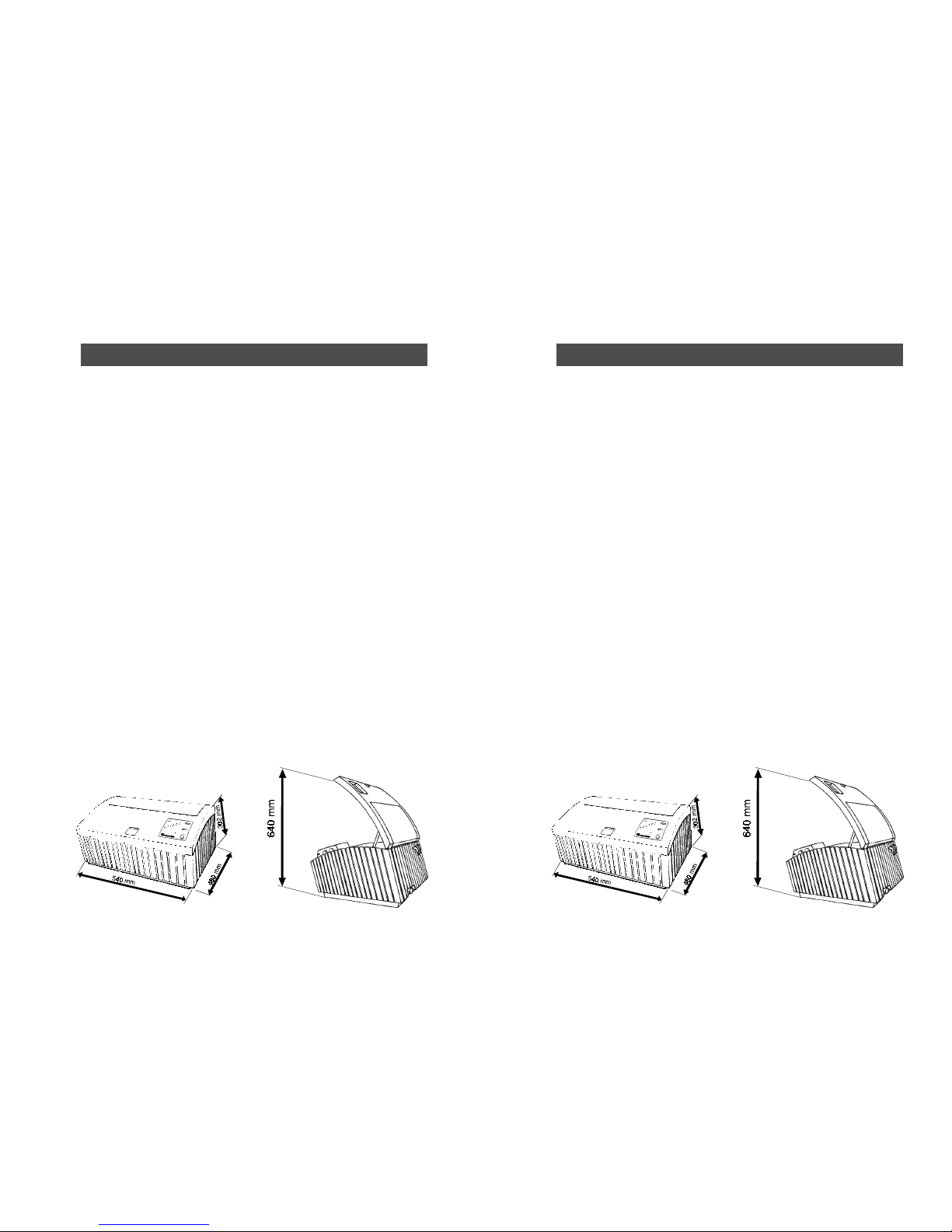
1. TECHNISCHE DATEN
Tiefe: 480 mm
Höhe: 302 mm
Höhe bei geöffnetem Deckel: 640 mm
Breite: 540 mm
Leergewicht: 11 kg
Wassermantelbad-Volumen: 3 L
Spannung: 230V 50/60Hz bzw.
115V 50/60Hz
Leistung: 850 W
zul. Umgebungstemperaturen:
- bei Betrieb +10° bis +30°C
- bei Lagerung + 5° bis +40°C
- bei Transport - 30° bis +60°C
max. Filmformat : 4x5"
max. Papierformat: 20x25/8x10"
max. Filmmengen:
10 135-12
5 135-36
6 120
12 9x12 cm
12 4x5"
max. Papiermengen:
2 9x13/4x5"
1 13x18/5x7"
1 18x24/7x9"
1 20x25/8x10"
1. TECHNICAL SPECIFICATION
Front-to-back size: 480 mm
Height: 302 mm
Height with cover open: 640 mm
Width: 540 mm
Empty weight: 11 kgs
Water jacket volume: 3 litres
Voltage: 230 V 50/60 Hz or
115 V 50/60 Hz
Power: 850 W
Adm. ambient temperatures:
- for operation +10° to +30°C
- for storage + 5° to +40°C
- for transport -30° to +60°C
Max. film size: 4x5"
Max. paper size: 20x25/8x10"
Max. film quantities:
10 135-12
5 135-36
6 120
12 9x12 cm
12 4x5"
Max. paper quantities:
2 9x13/4x5"
1 13x18/5x7"
1 18x24/7x9"
1 20x25/8x10"
Page 5

5
2. LIEFERUMFANG
1 Druckschlauch Art. Nr. 16171
1 Bedienungsanleitung Art. Nr. 86377
1 Film/Papiertrommel Art. Nr. 4218
1 Film/Papiertrommel Art. Nr. 4219
2 Deckel für Film/Papiertrommel Art. Nr. 91047
5 Filmspiralen 135/120 Art. Nr. 2502
1 Planfilmspirale Art. Nr. 2509n
1 Tanktopf Art.Nr. 02031
1 Achsrohr Art. Nr. 04043
2 Lamellenstopfen Art. Nr. 15042
1 Magnetventilkappe montiert Art. Nr. 15023
1 Rückschlagventil-Kappe montiert Art. Nr. 15024
1 Processor-Clean Art. Nr. 4181
1 Paar Seiten-Klappen 9 x12 Art. Nr. 07257
1 Paar Seiten-Klappen 4 x 5" Art. Nr. 07258
2 Ersatzrollen für Rollenbock Art. Nr. 93023
2. SCOPE OF SUPPLY
1 pressure hose Item No. 16171
1 instruction manual Item No. 86378
1 film/paper drum Item No. 4218
1 film/paper drum Item No. 4219
2 lid for film/paper drum Item No. 91047
5 film reels 135/120 Item No. 2502
1 sheet film reel Item No. 2509n
1 Tank body Item No. 02031
1 Core tube Item No. 04043
2 lamellar plug Item No. 15042
1 electrovalve cap, mounted Item No. 15023
1 check valve cap, mounted Item No. 15024
1 Processor-Clean Item No. 4181
1 pair of Sideholder 9 x 12 Item No. 07257
1 pair of Sideholder 4 x 5" Item No. 07258
2 Spare rolls for roller block Item No. 93023
Page 6

6
3. BEDIENUNGSELEMENTE
Bedienungselemente: Siehe letzte Seite
1 Netzschalter
2 Programmwahlschalter
3 Wässerungstaste / Reset Taste
4 Deckelverschlußtaste
5 Flaschenverschlüsse
6 Ablaufhahn für Wassermantelbad
7 Werte ändern
8 Enter-Taste
Anzeigen:
9 SET-LED
10 Wässerungs-LED
11 Chemieschritt-LED
12 Programmanzeige
13 Zeitenkorrekturanzeige
Anschlüsse:
14 temperierter Wasseranschluß (Druck 1-6 bar)
15 Wasseranschluß (mobile Versorgung)
16 Stromanschluß (mobile Versorgung)
17 Buchse externe 12 V Stromversorgung
18 Akkufach
19 Brauchwasserabfluß
20 Chemikalienabfluß
3. OPERATING ELEMENTS
Operating elements: see last page
1 Main switch
2 Program selecting switch
3 Rinsing button / Reset button
4 Lid closing button
5 Bottle caps
6 Outlet cock for water jacket
7 Modification of values
8 Enter-key
Indications:
9 SET LED
10 Rinsing LED
11 Solution step LED
12 Program indication
13 Time correction indication
Connections:
14 Temperature controlled water connection (pressure)
15 Water connection (mobile supply)
16 Power connection (mobile supply)
17 Socket external 12 V power supply
18 Accumulator compartment
19 Used water outlet
20 Solution outlet
Page 7

7
4. STICHWORTVERZEICHNIS
Seite Suchwort
9 Abfluß Wasser/Chemie
9 Chemikalienbehälter
9 Chemie- / Wasserverteiler
17 Deckelverschluß
33 externe Wasserversorgung
21-25 Programmbelegung
20/26 Reinigung
20 Reinigungsschlauch
11/32 Stromversorgung
15/17 Tankabdeckung
15/18 Tankkupplung
36 Transportkoffer
19/20 Wassermantelbad
10/33 Wasserzuleitung
4. INDEX
Page Search word
9 Outlet water/solution
9 Solution container
9 Solution- / water distributor
17 Cap closure
33 External water supply
21-25 Programm assignment
20/26 Cleaning
20 Cleaning hose
11/32 Power supply
15/17 Tank cover
15/18 Tank coupling
36 Transport case
19/20 Water jacket
10/33 Water inlet
Page 8
8
5. VORBEREITUNG
5.1 Auspacken
Entnehmen Sie das Gerät und alle im Karton befindlichen Teile der Verpackung.
Überprüfen Sie die Vollständigkeit der Teile mit der Information des Lieferumfanges
Kapitel 2.
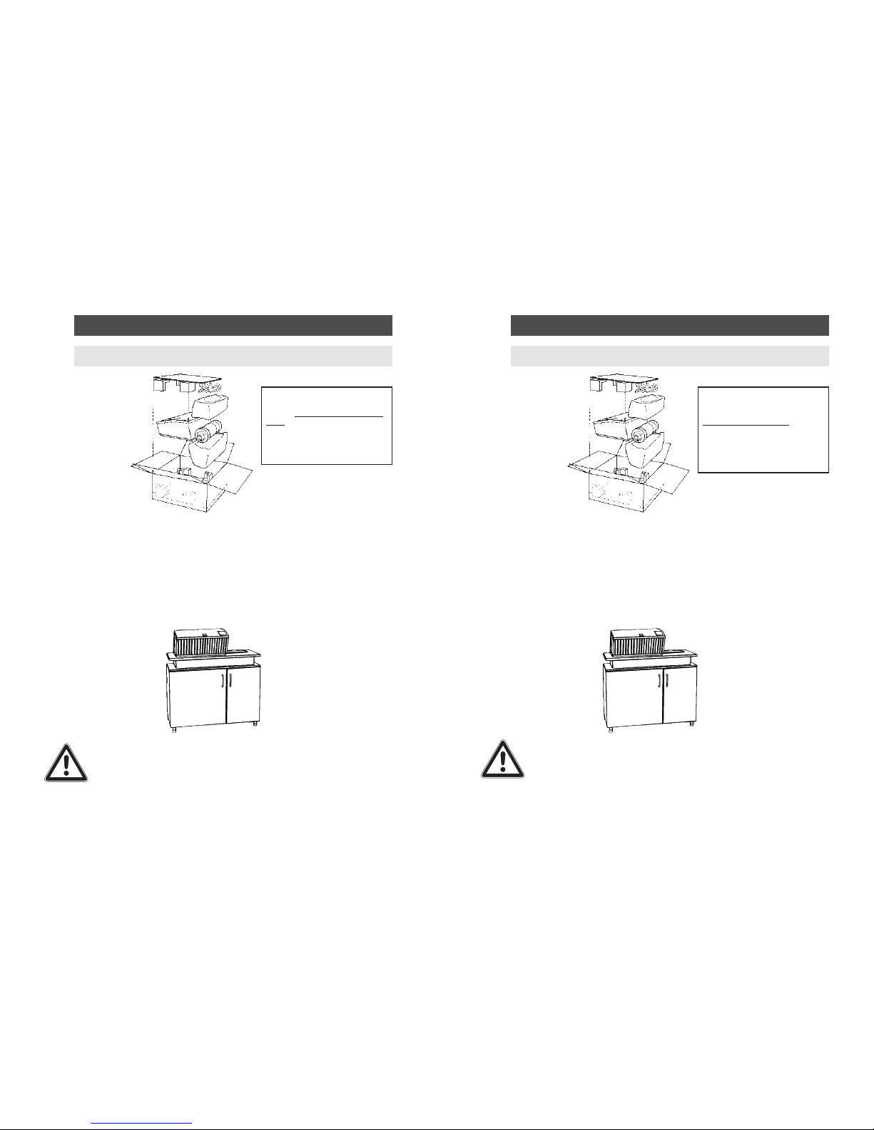
Bedenken Sie bei der Wahl des Standortes, daß ein temperierter Wasseranschluß, sowie
eine geerdete Steckdose und ein Wasserabfluß in erreichbarer Nähe sind. Das ATL 1500
muß nicht in einer Dunkelkammer installiert werden. Das ATL 1500 kann entweder auf
einem Tisch oder auf dem Unterschrank (Art. Nr. 4214) aufgestellt werden. Dieser
Unterschrank bietet eine ideale Arbeitshöhe für den Processor und Aufbewahrungsplatz
für das komplette Zubehör und die Vorratschemikalien (Kanister für die Vorratschemikalien sind im Lieferumfang des Unterschrankes enthalten).
Achtung: Stellen Sie das Gerät niemals in eine Laborwanne, in der sich
abfließendes Wasser stauen kann. Aus Sicherheitsgründen ist
die Bodenplatte des ATL 1500 an verschiedenen Stellen mit
Öffnungen versehen. Eindringendes Wasser kann zu einer
Beschädigung des Gerätes führen. Wenn das Gerät in einem mit
Wasser gefüllten Becken steht, greifen Sie nicht in das Wasser!
Ziehen Sie erst den Netzstecker heraus, um einen elektrischen
Schlag zu vermeiden.
Um einen sicheren Transport bei eventuellen Servicereparaturen zu gewährleisten, verwenden Sie bitte nur den
Originalkarton mit Einlagen und
verpacken Sie das Gerät gemäß
nebenstehender Abbildung. Für
Schäden, die durch unsachgemäße
Verpackung entstehen, kann keine
Haftung übernommen werden.
5. PREP ARA TIONS
5.1 Unpacking
Take the appliance and all other parts out of the box. Check the completeness of the
parts by means of the information about the scope of supply in Chapter 2.
For the choice of the location consider that a temperature-controlled water supply as
well as a grounded socket and a water drain are within reach. The ATL 1500 need not
be installed in a darkroom.
The ATL 1500 can either be placed on a table or on the cabinet (Item No. 4214). This
cabinet provides an ideal working height for the processor and storage space for the
complete accessories and the solution stocks. (Containers for the solution stocks are
part of the scope of supply of the cabinet.)
Note: Never place the appliance into a sink where outflowing water can
rise up. For safety reasons the bottom plate of the ATL 1500 has
openings at various points. Penetrating water can damage the
appliance. If the appliance is standing in a basin filled with water,
do not put your hand into the water! Pull the mains plug first to
prevent an electric shock.
To ensure a safe transport in case of
any required service repairs, please
use only the original packing with the
inlays and pack the instrument
according to the illustrations on this
page. We will not accept any liability
for damages caused by inexpert
packing.
Page 9

9
ATL 1500
Wasserabfluß
Siphon
Entlüftung
Gelb
Blau
5.2 Ablaufinstallationen
Stecken Sie den Abwasserschlauch in einen ausreichend großen Behälter oder fest an
eine Abwasserleitung.
Da bei einem E-6 Prozeß ca. 10 Liter Wasser benötigt werden ist, falls ein Auffangbehälter verwendet werden soll, auf eine ausreichende Größe des Behälters zu achten.
Der Anschlußstutzen des Abwasserschlauchs ist mit einem blauen Aufkleber gekennzeichnet. Der Schlauch muß immer mit Gefälle verlegt werden (Mindestgefälle 10 cm/m).
Achten Sie darauf, daß das Schlauchende nicht in das Wasserniveau eintaucht. Wenn
Schläuche nicht ordnungsgemäß installiert sind läuft Wasser bzw. Chemie über, d.h.
tritt im Bereich des Schlauchstutzen am Geräteboden aus, oder Wasser läuft in den
Chemikalienauffangbehälter bzw. Chemie in den Wasserauffangbehälter.
Falls der Wasserabfluß des ATL 1500 direkt an einen Siphon angeschlossen wird, muß
darauf geachtet werden, daß zwischen dem Siphon und dem ATL 1500 Wasserabfluß
eine Entlüftung vorgesehen wird.
5.2.1 Ablaufinstallation Chemikalien
Da bei einem E-6 Prozeß bis zu 4,5 Liter Chemikalien anfallen können ist, falls ein
Auffangbehälter verwendet werden soll, auf eine ausreichende Größe des Behälters zu
achten. Der Anschlußstutzen des Chemikalienablaufschlauchs ist mit einem gelben
Aufkleber gekennzeichnet.
Der Schlauch muß immer mit Gefälle verlegt werden. (Mindestgefälle 10 cm/m).
Achten Sie darauf, daß die Schlauchenden nicht in das Chemikalienniveau eintauchen.
Wenn Schläuche nicht ordnungsgemäß installiert sind läuft Wasser bzw. Chemie über,
d.h. tritt im Bereich des Schlauchstutzen am Geräteboden aus, oder Wasser läuft in den
Chemikalienauffangbehälter bzw. Chemie in den Wasserauffangbehälter.
5.2 Drain installations
Put the drain hose in a sufficiently sized container or connect it firmly to a drain pipe.
Since in an E-6 process about 10 litres of water are required, it must be ensured that if
you want to use a collecting container this must have a sufficient size. The drain hose
is identified with a blue label.
The hoses must always be installed with a gradient. Please make sure that the hose
ends do not dip into the water. Due to lacking deaeration this might otherwise lead to a
stemming of water and thus to damages of the appliance. In case hosesare not installed
properly, water or chemical solutions can overflow in the area of the hose connection
piece at the bottom of theunit or water can flow in the chemical collection container,
respectively chemicals in the water collection container.
In case the water outlet is directly connected with a syphon, an air escape must be
installed between syphon and water outlet of the processor.
5.2.1 Chemical draining installation
Since in an E-6 process up to 4.5 litres of solution may be used, it must be ensured that
if you want to use a collecting container this must have a sufficient size. The solution
drain hose is identified with a yellow label.
The hoses must always be installed with a gradient. Please make sure that the hose
ends do not dip into the solution. Due to lacking deaeration this might otherwise lead
to a stemming of solution and thus to damages of the appliance.
Yellow
Blue
ATL 1500
water outlet
Syphon
Air escape
Page 10

10
5.3 Wasseranschluß
Schließen Sie den beiliegenden Druckschlauch an eine temperierte Wasserzuleitung an.
Entfernen Sie zu diesem Zweck auf der Geräterückseite des ATL 1500 die Magnetventilkappe des Magnetventilanschlusses.
Achtung: Wasserdruck max. 6 bar.
“Temperiertes Wasser” bedeutet Wasser mit Prozeßtemperatur.
Speziell für diesen Zweck ist der JOBO Warmwasserdruckspeicher (Art. Nr. 4167)
geeignet. Für den E-6 Prozeß ist eine Waschwassertemperatur von 38 Grad ±1°C
empfehlenswert.
Bei anderen Prozessen ist die Waschwassertemperatur wesentlich unkritischer.
Beachten Sie bitte hierzu die Hinweise der Chemikalienhersteller.
5.4 Aufstellen und Ausrichten
Bringen Sie das Gerät in eine waagerechte Position. Die waagerechte Lage des
ATL 1500 ist nötig, um Filme und Papiere gleichmäßig entwickeln zu können. Eine
Hilfslinie in der Wanne erleichtert Ihnen das Ausrichten. Wenn Sie das ATL 1500
einschalten, füllt sich das Wassermantelbad automatisch mit Wasser. Vergleichen Sie
nun den Wasserspiegel mit der Linie im Gerät.
5.3 Water connection
Connect the enclosed pressure hose with a temperature-controlled water supply. For
this purpose remove the return flow safety device on the electrovalve connection on the
back side of the appliance.
Attention: Water pressure shall not exceed 6 bar.
Temperature-controlled water means water at process temperature.
Especially for this purpose the JOBO warm water pressure tank (Item No. 4167) is
suited. For the E-6 process, a rinsing water temperature of 38 ± 1°C is recommended.
With other processes the rinsing water temperature is much less critical. Please observe
the instructions of the chemical manufacturers.
5.4 Installation and adjustment
Bring the appliance into a level position. The level position of the ATL 1500 is
necessary to ensure a uniform development of films and papers. A marking line in the
trough makes adjustment easier for you. When you switch the ATL 1500 on, the water
jacket automatically fills with water. (Only for temperature-controlled processes like
E-6/C-41). Now compare the water level with the line in the appliance.
Page 11
11
5.5 Netzbetrieb
Betreiben Sie das Gerät nur mit der auf dem Typenschild im Innenbereich hinter dem
Bedienfeld angegebenen Spannung.
Verwenden Sie nur eine geerdete Steckdose. Achten Sie darauf, daß der Stromkreis, an
dem das Gerät betrieben wird, durch dieses nicht überlastet wird.
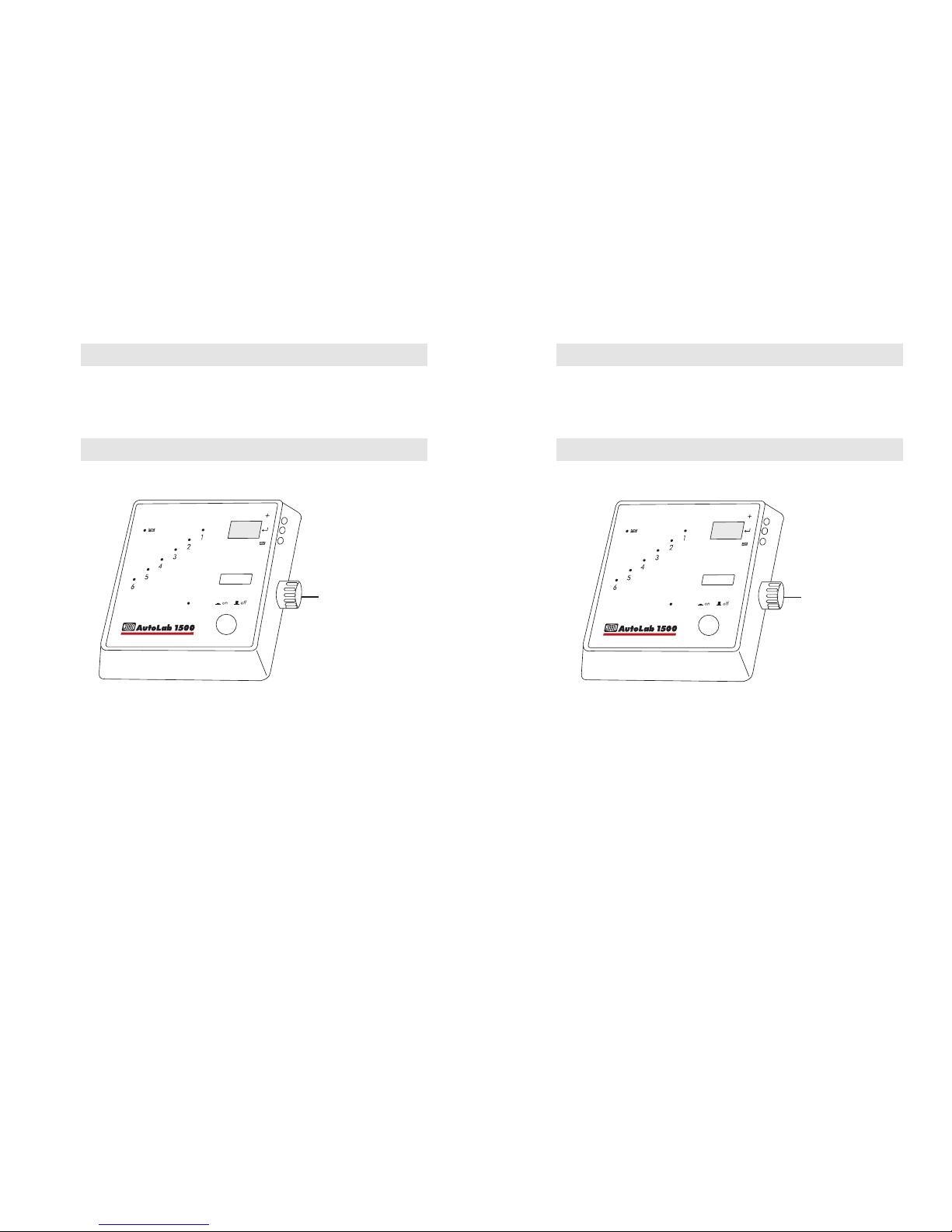
5.6 Programmwahl
Gewünschtes Programm durch Drehen des Programmwahlschalter einstellen.
Die Erläuterungen der zur Verfügung stehenden Programme finden Sie in den
Kapiteln:
Filmverarbeitung Kapitel 8
Papierverarbeitung Kapitel 9
Programmwahlschalter
5.5 Mains operation
Unit should only be used at the voltage indicated on the specification plate on the back side
of the contol panel.
Use only a grounded socket. Make sure that the line on which the appliance is
operated, is not overloaded by it.
5.6 Program selection
Set the desired program by turning the program selecting switch.
You will find explanations of the available programs in chapters:
Film processing Chapter 8
Paper processing Chapter 9
Programm selection switch
Page 12

12
5.7 Befüllen der Chemikalienbehälter
Chemikalienbehälter mit der benötigten Chemikalienmenge in Prozeßreihenfolge (1-6)
befüllen. Die zur Entwicklung benötigten Mengen können Sie an der Tabelle im
ATL 1500 ablesen.
Das Dosieren der drei gängigen Mengen wird Ihnen durch die in den Chemikalienbehältern installierten Füllmengenanzeigen erleichtert. Beim Einfüllen verdunkelt sich,
bei Erreichen der benötigten Chemiemenge das Füllstandsfenster. Wenn die Chemikalienbehälter voll gefüllt sind, fingerbreit unter dem Rand, entspricht das ca. 650 ml.
Hinweis: Um eine reproduzierbare Entwicklungsqualität gewährleisten
zu können, muß die eingefüllte Chemie eine Temperatur von
weniger als 30°C bei 38°C– und weniger als 22°C bei 24°C
–
Prozessen haben.
1x 135
6x 4x5
2x 135
2x 120
2x 4x5
1x 120
12x 4x5
5x 135
6x 120
3x 120
auf
zu
5.7 Filling the solution containers
Fill the solution containers with the required solution quantity in the order of (1-6)
processing. You can take the quantities required for development from the table in
the ATL 1500.
The dosing of the three common quantities is made easier by the filling quantity
indications installed the solution containers. When they are filled, the filling level
window gets dark when the required solution quantity is reached. When the solution
containers are completely filled, i.e. about an inch under the top, this corresponds to
about 650 ml.
Note: In order to ensure repeatable quality results, the solutions, which are
put into bottles 1 to 6 must begin with a temperature of less than 30°C
with 38°C processes and less than 22°C with 24°C processes.
1x 135
6x 4x5
2x 135
2x 120
2x 4x5
1x 120
12x 4x5
5x 135
6x 120
3x 120
close
open
Page 13

13
5.8 Einlegen von Film und Papier
Achtung: Verwenden Sie nur ganz trockene Spiralen und Tanks. In feuchte
Spiralen lassen sich Filme fast nicht einspulen, da die Emulsion
im Randbereich quillt und damit den Film klebrig macht.
Wassertropfen, die in der Vorwärmphase über den Film laufen,
verursachen Streifen und Schlieren.
KB und Rollfilmspirale ( Art. Nr. 2502)
Die Spirale kann ohne zusätzliche Ladehilfe betückt werden. Der Duoclip ermöglicht
die gleichzeitige Entwicklung von zwei 120ern oder zwei 135-12 in einer Spirale.
Die Spirale läßt sich durch Linksdrehen (über einen kleinen Widerstand) und Abziehen
der oberen Spiralenhälfte auf die gewünschte Filmbreite einstellen.
Durch anschließendes Rechtsdrehen der oberen Spiralenhälfte über den kleinen
Widerstand bis zum Anschlag wird diese dann wieder arretiert.
Handling:
Legen Sie, bevor Sie das Licht ausschalten, alle benötigten Teile in Griffweite bereit.
Öffnen Sie bei allen Spiralen den Duoclip, es sei denn, Sie wollen die Spiralen nur im
äußeren Bereich mit einem kurzen Film bestücken. Bei absoluter Dunkelheit wird der
KB-Film gerade abgeschnitten und von den Rollfilmen das Schutzpapier entfernt. Der
Filmanfang wird nun, mit der Schichtseite nach innen, in den Spiralengang bis hinter
die Griffmulde eingeschoben.
Rechter Zeigefinger auf die Filmkante in der Griffmulde legen. Spulenhälfte bis zum
Anschlag im Uhrzeigersinn drehen. Rechten Zeigefinger anheben und den selben
Vorgang mit der linken Spiralenhälfte und linkem Zeigefinger wiederholen.
35 mm
120/220 mm
5.8 Inserting film and paper
Note: Use only completely dry reels and tanks. It is almost impossible to
load films into moist reels, because the emulsion swells around the
edge and makes the film sticky. Drops of water running over the
film in the preheating phase will cause striae and streaks.
Miniature film and rollfilm reel (Item No. 2502)
The reel can be loaded without any additional device. The Duoclip permits the
simultaneous development of two 120 films or two 135-12 films in one reel.
By turning the top half counterclockwise (over a slight resistance) and pulling it off,
the reel can be adjusted to the required film width.
By subsequent clockwise turning of the top reel half over the slight resistance to the
stop this is fixed again.
Handling:
Before turning out the light, place all items you need within reach. Open the Duoclip
on all reels, unless you want to load the reels only in the outer zone with a short film.
In complete darkness, the miniature film is cut off straight, and the protective paper is
removed from the rollfilms. The beginning of the film, with the emulsion side inward,
is now pushed into the reel until it is behind the recess.
Put the right index finger on the film edge in the recess. Turn the reel half clockwise to
the stop. Lift the right index finger and repeat the same procedure with the left reel half.
35 mm
120/220 mm
Page 14

14
Durch abwechselndes Verdrehen der Spiralenhälften gegeneinander den Film ganz in
die Spirale einziehen. Beim Einspulen von zwei Filmen (120ern) den ersten Film bis
zum Anschlag einspulen, dann den Duoclip herunterdrücken und den nächsten Film
einspulen. Der heruntergedrückte Duoclip verhindert, daß Sie den zweiten Film über
den ersten schieben.
Planfilmspirale (Art. Nr. 2509n)
Legen Sie, bevor Sie das Licht ausschalten alle benötigten Teile in Griffweite bereit.
Die Spirale läßt sich durch Linksdrehen (über einen kleinen Widerstand) und Hochziehen der oberen Spiralenhälfte auf die gewünschte Filmbreite einstellen.
Durch anschließendes Rechtsdrehen der oberen Spiralenhälfte bis über den kleinen
Widerstand bis zum Anschlag wird diese dann wieder arretiert.
Handling:
Die Planfilme werden bei absoluter Dunkelheit mit der Schichtseite nach innen,
beginnend mit dem inneren Spiralengang, eingeschoben. Nachdem alle Filme,
max. 6, eingeschoben sind, werden die Seitenklappen eingesetzt.
Für den regelmäßigen Einsatz der Spirale empfehlen wir den Lader 2508, mit den
Schablonen:
2510 für 6X9 2511 für 9X12 2512 für 4X5'
4x 5"
6x 9"
9x12"
By alternately turning the reel halves against each other, load the complete film into
the reel. When loading two films (120), load the first film to the stop, then press
down the Duoclip and load the next film. The pressed down Duoclip prevents the
second film from being pushed over the first.
Sheet film reel (Item No. 2509n)
Before turning out the light, place all items you need within reach.
The reel can be adjusted to the required film width by turning the top reel half
counterclockwise (over a slight resistance) and pulling it up.
By subsequently turning the top reel half clockwise over the slight resistance to the
stop it is fixed again.
Handling:
In complete darkness, the sheet films are pushed in, with the emulsion side inward
and beginning with the inner reel spiral. When all films, six at max., are loaded, the
spiral flaps are put in.
For a regular use of the reel we recommend the loader 2508, with the templates:
2510 for 6x9 2511 for 9x12 2512 for 4x5"
4x 5"
6x 9"
9x12"
Page 15

15
5.9 Bestücken der Tanks
Schieben Sie die bestückten Spiralen auf das Achsrohr und geben Sie sie in den Tank.
Beachten Sie, daß die Trichteröffnung nicht mit dem Lamellenstopfen (Art. Nr. 15042)
versehen ist. Setzen Sie den Deckel auf den Tank auf, achten Sie dabei darauf, daß der
rote Schiebering noch nicht herunter gedrückt ist. Wenn der Deckel richtig aufliegt und
angedrückt ist, drücken Sie den roten Schiebering rundherum vollständig herunter.
Achtung: Wenn der Trichter oder das Achsrohr versehentlich nicht
eingesetzt werden, so werden die Filme durch einfallendes
Licht angeschleiert und somit unbrauchbar.
Der Tank kann jetzt am Kupplungsflansch des ATL 1500 angekuppelt und der
Prozeßablauf gestartet werden. Nach Prozeßende nehmen Sie den Tank aus dem
ATL 1500, ziehen den Schiebering hoch und heben den Tankdeckel ab, um die Filme
zu entnehmen.
5.9 Loading the tanks
Slide the loaded reels onto the centre tube and put them into the tank. Please make sure
that the lamellar plug (Item No. 15042) is not on the funnel opening. Place the cover
on the tank, make sure that the red slide ring is not yet pushed down. When the cover is
in the right position and is pressed on, push the red slide ring right down.
Note: When the funnel or the centre tube are accidentally not put in,
incoming light will fog the films and make them useless.
The tank can now be pushed onto the coupling flange of the ATL 1500 and the process
started. After the end of the process pull the slide ring up and lift the tank cover off to
remove the films.
Page 16

16
6x 9x12/4x5"
12x 9x12/4x5"
5.10 Füllmengen bei der Filmentwicklung
Die angegebenen Füllmengen stellen lediglich eine gleichmäßige Benetzung der Filme
sicher. Bei den unterschiedlichen Chemikalienanbietern können sich durchaus Füllmengen ergeben, die über unseren Benetzungsmengen liegen. Die in der Tabelle
angegebenen Füllmengen liegen z.T. unter den Füllmengen, die durch die optischen
Einfüllhilfen erreicht werden.
Tank
Spiralen
Anzahl 1x 1x 2x 1x 2x 2x 3x 4x 5x
Filme 2502 2502 2502 2509 2509 2502 2502 2502 2502
1x 135/36 170ml
2x 135/36 250ml
3x 135/36 500ml
4x 135/36 500ml
5x 135/36 600ml
1x 120 125ml
2x 120 250ml
3x 120 330ml
4x 120 500ml
5x 120 550ml
6x 120 660ml
1x 220 250ml
2x 220 500ml
3x 220 660ml
250ml
500ml
6x 9x12/4x5"
12x 9x12/4x5"
5.10 Filling quantities for film processing
The filling quantities given below only guarantee an even wetting of the films. With
the different solution manufacturers there may well be filling quantities that are higher
than our wetting quantities. The filling quantities given in the table are sometimes
lower than the filling quantities indicated by the visual filling aids.
Tank
Reels
1x 1x 2x 1x 2x 2x 3x 4x 5x
Films 2502 2502 2502 2509 2509 2502 2502 2502 2502
1x 135/36 170ml
2x 135/36 250ml
3x 135/36 500ml
4x 135/36 500ml
5x 135/36 600ml
1x 120 125ml
2x 120 250ml
3x 120 330ml
4x 120 500ml
5x 120 550ml
6x 120 660ml
1x 220 250ml
2x 220 500ml
3x 220 660ml
250ml
Page 17

17
5.11 Bestücken der Tanks (Papier)
Achtung: Verwenden Sie nur saubere und ganz trockene Tanks und
Deckel. Wassertropfen, die über Papier laufen, verursachen
Streifen und Schlieren.
Um den Deckel abnehmen zu können, schieben Sie den Schiebering hoch und öffnen
den Tank.
Das Papier legen Sie bei absoluter Dunkelheit mit der Schichtseite nach innen ein
(Trägerseite des Papiers zur Trommelwand).
Danach wird der Tankdeckel aufgesetzt und der Schiebering fest heruntergedrückt.
Achtung: Bei der Papierentwicklung muß die Trichteröffnung mit dem
beiliegenden Lamellenstopfen (Art. Nr. 15042) verschlossen
werden.
5.11 Loading the tanks (paper)
Note: Use only clean and completely dry tanks and covers. Drops
of water that run over the paper before processing will cause
striae and streaks.
To lift off the cover, push the slide ring upward and open the tank.
In complete darkness put the paper in, with the coated side inward. (Carrier side of the
paper towards the drum side)
Then the tank cover is replaced and the slide ring pushed down firmly.
Note: For paper development, the funnel opening must be closed with the
enclosed lamellar plug (Item No. 15042).
Page 18

18
Tank an ATL 1500 ankuppeln und den Prozeß starten.
Nach Prozeßende wird das Papier entnommen und getrocknet.
5.12 Füllmengen bei der Raumtemperatur-Papierentwicklung
Füllmengen Tank Bestückung Format
40ml “klein” 2 9x13/4x5"
100ml “groß” 1 13x18/5x7"
1 18x24/7x9"
1 20x25/8x10"
Couple the tank to the ATL 1500 and start the process.
After the end of the process, the paper is removed and dried.
5.12 Filling quantities for paper processing
Filling quantities Tank Amount Size
40 ml “small” 2 9x13/4x5"
100 ml “large” 1 13x18/5x7"
1 18x24/7x9"
1 20x25/8x10"
Page 19

19
6. PROZEßSTART
6.1 Vor dem Start
Kuppeln Sie den bestückten Tank an das ATL 1500 an.
Nachdem alle Flaschendeckel geschlossen wurden, schließen Sie den Gerätedeckel.
Überprüfung: Waschwassertemperatur eingestellt und Zulaufhahn ge-
öffnet?
Programm entspricht der eingefüllten Chemie?
Auffangbehälter nehmen anfallende Menge noch auf?
Ablaufhahn für Wassermantelbad geschlossen?
6.2 Starten eines Prozeßablaufs
Schalten Sie das Gerät am Netzschalter ein. Das ATL 1500 füllt jetzt selbständig das
Mantelbad und beginnt mit der Temperierung der Chemikalien und der Trommel.
Wenn die richtige Temperatur erreicht ist, wird die erste Chemikalie in den Tank
eingefüllt. (Abhängig von der Chemikalienmenge und der Wasser- und Chemikalientemperatur nach 10 bis 35 Minuten). Der Prozeßablauf ist vollautomatisch. Das
Prozeßende wird durch ein akustisches Signal (unterbrochener Piepton) angezeigt.
Achtung: Nach dem Prozeßstart darf der Gerätedeckel nicht mehr
geöffnet werden, da sonst der Prozeß unterbrochen und
nach einigen Sekunden abgebrochen wird!
Fehlbedienung:
Bei einer Fehlbedienung, z.B. Starten eines falschen Prozesses,
gehen Sie folgendermaßen vor:
Sie schalten das Gerät aus, öffnen den Deckel, stellen das
richtige Programm ein, schließen den Deckel und starten das
Gerät durch erneutes Einschalten.
Wurde das Gerät bei offenem Deckel gestartet, ertönt ein
Dauerpiepton. Schalten Sie das Gerät ab, schließen den Deckel
und starten Sie das Gerät erneut nach 10 Sekunden.
Wichtig: Zwischen dem Ein- und Ausschalten müssen
mindestens 10 Sekunden vergehen, da das Gerät über
den Netzschalter auf die Anfangsposition zurückgesetzt wird. (RESET)
6. PROCESS START
6.1 Before starting
Connect the loaded tank to the ATL 1500.
When all bottle caps are closed, close the appliance cover.
Check: Rinsing water temperature set and feed cock opened?
Program corresponds to the filled in solution?
Time controller ±% set to the right value?
Enough space in the collecting containers for the processed
quantities?
Is drain faucet for water jacket closed?
6.2 Starting a process
Switch the appliance on with the mains switch. The ATL 1500 now automatically fills
the water jacket and starts bringing the solutions and the drum to the correct
temperature. When the correct temperature is reached, the first solution is filled into
the tank. (Depending on the solution quantity and the temperature after
10 to 35 minutes.) The process runs fully automatically. The end of the process is
indicated by an acoustic signal (interrupted beep).
Note: After the process start the appliance cover must not be
opened, because this will interrupt the process!
Operating error:
In case of an operating error, e.g. starting of wrong process, proceed
as follows:
Switch the appliance off, open the cover, set the right program,
close the cover and start the appliance again by switching it on.
If the appliance was started with the cover open, you will hear
a continuing beep. Switch the appliance off, close the cover
and start it again after 10 seconds.
Important: Between switching on and off there must be an interval
of at least 10 secs, because the appliance is set back to
the starting position by the mains switch (RESET).
Page 20

20
7. PROZEßENDE
Nach Beendigung des Prozesses schalten Sie das Gerät aus und öffnen den Gerätedeckel. Nachdem Sie den Tank abgenommen haben, werden nun die Filme in einem
separaten Behälter mit Stabibad behandelt und zum Trocknen aufgehängt.
Reinigen des Gerätes:
Stellen Sie dazu das Programm auf “CLEANING” und schalten das Gerät bei geöffnetem Gerätedeckel durch Drücken der ON/OFF-Taste ein. Alle Flaschen werden mit
Wasser aus der Handbrause gefüllt. Nehmen Sie den Wässerungsschlauch aus der
Halterung, halten den Auslauf über die geöffneten Flaschen und betätigen Sie die
Wässerungstaste.
1. Chemikalienflaschen schließen
2. Den benutzten Tank mit dem Achsrohr und den Spiralen ankuppeln.
3. Prüfen, ob die Auffangbehälter das Volumen der Wässerungsmenge
bzw. der Chemikalienmenge aufnehmen können.
4. Den Gerätedeckel schließen. Das Gerät startet selbständig das
Reinigungsprogramm.
Für eine 100% Reinigung des ATL 1500 (notwendig wenn ein anderer Prozeß verarbeitet werden soll) ist das Reinigungsprogramm 3x zu wiederholen.
Eine Reinigung des Gerätes und der Chemikalienbehälter kann entfallen,
wenn am selben Tag nochmals der gleiche Prozeß verarbeitet werden soll.
Tank, Achsrohr und Spiralen sind nach Reinigung und anschließender Trocknung
wieder einsatzbereit.
Hinweis: Der verbleibende Wasserrest in den Chemikalienbehältern
(3-5 ml) muß nicht entfernt werden, da sich diese Wassermenge prozeßneutral verhält.
Aus Gründen der Reinhaltung und der Funktionssicherheit des Gerätes wird das
Entleeren des Wassermantelbades nach Abschluß des Arbeitstages empfohlen.
7. PROCESS END
After the end of the process you switch the appliance off and open the cover. When
you have removed the tank, the films are now treated with stabilizer in a separate
container and hung up to dry.
Cleaning:
For this purpose, set the program to “CLEANING” and start the appliance with the
cover open.. All bottles are filled with water from the hand spray head. Take the
rinsing hose from the holder, hold the outlet over the opened bottles and press the
water button.
1. Close the solution bottles.
2. Connect the used tank, with the centre tube and reels.
3. Check whether there is sufficient empty capacity in water and chemical
reclamation tank.
4. Close the appliance cover, the appliance automatically starts the
cleaning program.
For a 100% cleaning of the ATL 1500, necessary for running another process, the
cleaning program must be repeated 3x.
Cleaning of the appliance and the solution bottles is not required if the
same process is to be run once more on the same day.
Tank, centre tube and reels are ready for use again after cleaning and drying.
Note: The remaining water in the solution containers (3-5 ml) need not
be removed, because this water quantity is neutral to the processes.
For reasons of keeping the appliance clean and in safe working condition, it is
recommended to empty the water jacket when the working day is completed.
Page 21

21
8. FILMVERARBEITUNG
1. E-6 Standard
Temperatur: 38.0° Flasche Zeit
Erstentwickler 1: 6:30
wässern : 2:00
Umkehrbad 2: 2:00
Farbentwickler 3: 5:00
Konditioner 4: 2:00
Bleichbad 5: 6:00
Fixierer 6: 4:00
wässern : 4:00
2. E-6 +1
Temperatur: 38.0° Flasche Zeit
Erstentwickler 1: 8:30
wässern : 2:00
Umkehrbad 2: 2:00
Farbentwickler 3: 5:00
Konditioner 4: 2:00
Bleichbad 5: 6:00
Fixierer 6: 4:00
wässern : 4:00
3. E-6 -1
Temperatur: 38.0° Flasche Zeit
Erstentwickler 1: 4:30
wässern : 2:00
Umkehrbad 2: 2:00
Farbentwickler 3: 5:00
Konditioner 4: 2:00
Bleichbad 5: 6:00
Fixierer 6: 4:00
wässern : 4:00
8. FILM PROCESSING
1. E-6 Standard
Temperature: 38.0° Bottle Time
First developer 1: 6:30
Rinsing : 2:00
Reversal solution 2: 2:00
Colour developer 3: 5:00
Conditioner 4: 2:00
Bleach solution 5: 6:00
Fixing solution 6: 4:00
Rinsing : 4:00
2. E-6 + 1
Temperature: 38.0° Bottle Time
First developer 1: 8:30
Rinsing : 2:00
Reversal solution 2: 2:00
Colour developer 3: 5:00
Conditioner 4: 2:00
Bleaching solution 5: 6:00
Fixing solution 6: 4:00
Rinsing : 4:00
3. E-6 - 1
Temperature: 38.0° Bottle Time
First developer 1: 4:30
Rinsing : 2:00
Reversal solution 2: 2:00
Colour developer 3: 5:00
Conditioner 4: 2:00
Bleaching solution 5: 6:00
Fixing solution 6: 4:00
Rinsing : 4:00
Page 22

22
4. E-6 3 Bad Standard
Temperatur: 38.0° Flasche Zeit
Erstentwickler 1: 6:30
wässern : 2:30
Farbentwickler 2: 6:00
wässern : 2:30
Bleichfix 3: 6:00
wässern : 4:00
5. E-6 3Bad +1
Temperatur: 38.0° Flasche Zeit
Erstentwickler 1: 8:30
wässern : 2:30
Farbentwickler 2: 6:00
wässern : 2:30
Bleichfix 3: 6:00
wässern : 4:00
6. C-41 3 Bad
Temperatur: 38.0° Flasche Zeit
Farbentwickler 1: 3:15
Bleichbad 2: 6:00
wässern : 1:00
Fixierer 3: 6:00
wässern : 4:00
7. C-41 3 Bad +1
Temperatur: 38.0° Flasche Zeit
Farbentwickler 1: 3:45
Bleichbad 2: 6:00
wässern : 1:00
Fixierer 3: 6:00
wässern : 4:00
4. E-6 3 solution standard
Temperature: 38.0° Bottle Time
First developer 1: 6:30
Rinsing : 2:30
Colour developer 2: 6:00
Rinsing : 2:30
Bleachfix 3: 6:00
Rinsing : 4:00
5. E-6 3 solution + 1
Temperature: 38.0° Bottle Time
First developer 1: 8:30
Rinsing : 2:30
Colour developer 2: 6:00
Rinsing : 2:30
Bleachfix 3: 6:00
Rinsing : 4:00
6. C-41 3 solution
Temperature: 38.0° Bottle Time
Colour developer 1: 3:15
Bleaching solution 2: 6:00
Rinsing : 1:00
Fixing solution 3: 6:00
Rinsing : 4:00
7. C-41 3 solution
Temperature: 38.0° Bottle Time
Colour developer 1: 3:45
Bleaching solution 2: 6:00
Rinsing : 1:00
Fixing solution 3: 6:00
Rinsing : 4:00
Page 23

23
8. C-41 2 Bad
Temperatur: 38.0° Flasche Zeit
Farbentwickler 1: 3:15
Bleichfix 2: 8:00
wässern : 4:00
In allen Prozeßabläufen ist eine ausreichende Vorwärmzeit des Tanks
enthalten.
9. S/W 5
Temperatur: 24.0° Flasche Zeit
vorwässern: 5:00
Erstentwickler 1: 5:00
Stoppbad 2: 1:00
Fixierer 3: 6:00
wässern : 4:00
10. S/W 7
Temperatur: 24.0° Flasche Zeit
vorwässern: 5:00
Erstentwickler 1: 7:00
Stoppbad 2: 1:00
Fixierer 3: 6:00
wässern : 4:00
11. S/W 9
Temperatur: 24.0° Flasche Zeit
vorwässern: 5:00
Erstentwickler 1: 9:00
Stoppbad 2: 1:00
Fixierer 3: 6:00
wässern : 4:00
8. C-41 2 solution
Temperature: 38.0° Bottle Time
Colour developer 1: 3:15
Bleachfix 2: 8:00
Rinsing: : 4:00
In all processes a sufficient pre-heating time of the tank is included.
9. B/W 5
Temperature: 24.0° Bottle Time
Pre-rinsing 5:00
First developer 1: 5:00
Stop solution 2: 1:00
Fixing solution 3: 6:00
Rinsing : 4:00
10. B/W 7
Temperature: 24.0° Bottle Time
Pre-rinsing 5:00
First developer 1: 7:00
Stop solution 2: 1:00
Fixing solution 3: 6:00
Rinsing : 4:00
11. B/W 9
Temperature: 24.0° Bottle Time
Pre-rinsing 5:00
First developer 1: 9:00
Stop solution 2: 1:00
Fixing solution 3: 6:00
Rinsing : 4:00
Page 24

24
12. S/W 11
Temperatur: 24.0° Flasche Zeit
vorwässern: 5:00
Erstentwickler 1: 11:00
Stoppbad 2: 1:00
Fixierer 3: 6:00
wässern : 4:00
13. S/W 14
Temperatur: 24.0° Flasche Zeit
vorwässern: 5:00
Erstentwickler 1: 14:00
Stoppbad 2: 1:00
Fixierer 3: 6:00
wässern : 4:00
Tabelle zur Ermittlung von 20°C abweichenden Entwicklungszeiten
Beispiel:
Die Entwicklungszeit bei
20°C beträgt 17 Minuten.
Gehen Sie von dem Punkt
20°C/17 Min. aus entlang
der diagonalen Kennlinie
nach oben bis Sie die 24°CLinie kreuzen. Wenn Sie
nun von diesem Punkt senkrecht nach unten gehen, erhalten Sie die neue Entwicklungszeit.
Diese Angaben sind
Näherungswerte.
12. B/W 11
Temperature: 24.0° Bottle Time
Pre-rinsing 5:00
First developer 1: 11:00
Stop solution 2: 1:00
Fixing solution 3: 6:00
Rinsing : 4:00
13. B/W 14
Temperature: 24.0° Bottle Time
Pre-rinsing 5:00
First developer 1: 14:00
Stop solution 2: 1:00
Fixing solution 3: 6:00
Rinsing : 4:00
Nomograph for determining development times for temperatures other
than 20°C
Example:
The development time is
17 minutes at 20°C. First,
find the inter- section point
of 20°C and 17 minutes.
Then, move upwards along
the diagonal line from this
point until you reach the
line at 24°C. The revised
processing time can now
be read from the horizontal
axis directly below the
point you are at.
These values should be
considered approximations only.
Page 25

25
9. PAPIERVERARBEITUNG
14. RA-4 (MONO PK RT)
Temperatur: 24.0° Flasche Zeit
Farbentwickler 1: 1:30
Stoppbad 2: 0:30
Bleichfix 3: 2:00
wässern : 2:00
9. PAPER PROCESSING
14. RA-4 (MONO PK RT)
Temperature: 24.0° Bottle Time
Colour developer 1: 1:30
Stop solution 2: 0:30
Bleaching solution 3: 2:00
Rinsing : 2:00
Page 26

26
10. PFLEGE UND WA RTUNG
15. Reinigung
Flasche 1: 0:05
Flasche 2: 0:05
Flasche 3: 0:05
wässern : 2:00
16. Reinigung
Flasche 1: 0:05
Flasche 2: 0:05
Flasche 3: 0:05
Flasche 4: 0:05
Flasche 5: 0:05
Flasche 6: 0:05
wässern : 2:00
Pflege/Wartung:
- Wassermantelbad nach Arbeitsende ablassen.
- Regelmäßig nach Arbeitsende Reinigungsprogramm durchführen.
- Chemikalienspritzer sofort entfernen.
- Für alle Kalkrückstände, Algen und Farbentwicklerflecken benutzen Sie ProcessorClean (Art. Nr. 4181) (im Lieferumfang enthalten). Für die Reinigung des
ATL 1500 lösen Sie 5 Eßlöffel Reiniger in 3 Liter warmem Wasser vollständig auf
und geben Sie die Lösung in das leere Mantelbad. Starten Sie das Gerät mit geöffnetem Gerätedeckel auf Programm E-6 und lassen Sie das Gerät für
ca. zwei Stunden eingeschaltet. Gerät ausschalten. Wassermantelbad ablassen, mit
klarem Wasser nachspülen und Ablaufhahn schließen.
- Um die Flaschendichtungen zu schonen, sollten die Deckel bei Nichtgebrauch
geöffnet bleiben.
- Der Gerätedeckel kann trotz geöffneter Flaschendeckel geschlossen werden.
Achtung: Das Gerät darf zur Reinigung nicht in eine senkrechte Lage
gebracht werden, da auslaufende Wasser- und Chemikalienreste
in das Gerät eindringen und einen Geräteschaden verursachen
können. Aus diesem Grund auch nicht mit dem Wasserschlauch
das ATL 1500 absprühen.
10. CARE AND MAINTENANCE
15. Cleaning
Bottle 1: 0:05
Bottle 2: 0:05
Bottle 3: 0:05
Rinsing : 2:00
16. Cleaning
Bottle 1: 0:05
Bottle 2: 0:05
Bottle 3: 0:05
Bottle 4: 0:05
Bottle 5: 0:05
Bottle 6: 0:05
Rinsing : 2:00
Care/Maintenance:
- Empty water jacket after the end of work.
- Regularly run the cleaning program after the end of work.
- Immediately wipe off solution splashes.
- Use Processor-Clean (Item No. 4181) (included in the supply) for all furrings, algae
and colour developer stains. For cleaning the ATL 1500, dissolve 5 tablespoons of
cleaner in 3 liters of warm water and put this solution in the water jacket. Start the
appliance with the cover open in the program E-6 and leave it switched on for about
two hours. Switch unit off. Then empty the water jacket, rinse with the hand spray
head and close drain faucet.
- In order to avoid wearing of the bottle sealing rings, leave cover open when not in use.
- Cover of processor can be closed in spite of open bottle lids
Note: For cleaning, the aapliance must not be brought into a vertical
position, because outflowing water and solution remainders will
penetrate into the appliance and damage it. For this reason
never spray off ATL 1500 with water hose.
Page 27

27
11. TROUBLES
11.1 Appliance troubles
Trouble Cause Remedy
no heating overheating protection is call service
triggered
water jacket not filled Check water supply
when using the mobile water Fill up water jacket by hand
supply water jacket not
filled up
no LED on Electricity disconnected check socket
no power
Internal fuse triggered Switch off and switch on
again after about 15 min.
bottle not empty bottle not tight Exchange bottle lid, test
cleaning program
Bottle lid is not closed Make sure that lids of bottles
are closed before starting the
process
does not start appliance cover not closed switch appl. off,
warning by cont. beep close cover, switch on again
after 5 seconds
when using the mobile water Fill up water jacket by hand
supply water jacket not
Results in small and circulation pump failure call service
large tank are
different
11. STÖRUNGEN
11.1 Gerätestörungen
Störung Ursache Behebung
heizt nicht Überhitzungsschutz Service kontakten
ausgelöst
Mantelbad nicht gefüllt Bei stationärem Wasser-
anschluß Wasserzuleitung prüfen
Bei Benutzung der mobilen Wasser im Mantelbad von
Wasserversorgung Hand auffüllen
keine LED an Stromzufuhr unterbrochen Steckdose überprüfen
Interne Sicherung ausgelöst ausschalten, nach ca.
15 Min. einschalten
Flasche nicht leer Flasche nicht dicht Flaschendeckel wechseln
Test ReinigungsProgramm
Flaschen-Deckel nicht Vor Prozeßstart sichergeschlossen stellen, daß die Flaschen-
deckel geschlossen sind
Startet nicht Gerätedeckel nicht Gerät ausschalten, Deckel
geschlossen schließen, nach 5 Sek.
Warnung durch Dauerton wieder einschalten
Bei Benutzung der Wasser im Mantelbad von
mobilen Wasserversorgung Hand auffüllen
Ergebnisse im Umwälzpumpe ausgefallen Service kontakten
kleinen und großen
Tank sind unterschiedlich
Page 28

28
Trouble Cause Remedy
Processor does not a) When fixed to water
wash supply
Water supply is interrupted Check water supply
Is water stop triggered?
External water supply is Disconnect plug of external
connected
water supply
Magnet valve does not open call service
b) When applying mobile
water supply
Not enough water in the tank Refill tank before starting
a process
External pump has sucked air Fill up tank. Briefly check
with program B/W 5 and
connected tank. When water
was pumped, switch off
processor and empty by
hand.
External pump does not call service
function
Störung Ursache Behebung
Gerät wässert nicht a) bei stationärem Wasser-
anschluß
Wasserzulauf unterbrochen Wasserzulauf prüfen
Wasserstop ausgelöst?
Stecker für externe Pumpe Stecker für externe Pumpe
steckt herausziehen
Magnetventil öffnet nicht Service kontakten
b) bei mobiler Wasser-
versorgung
zu wenig Wasser im Kanister Kanister vor Prozeßstart
auffüllen
externe Pumpe hat Luft ange- Kanister auffüllen
saugt Kurztest mit B/W 5 und an-
kuppelten Tank
Gerät ausschalten nachdem
Wasser gepumpt wurde
und Tank von Hand
entleeren
externe Pumpe läuft nicht Service kontakten
Page 29

29
11.2 Problems
Problem Cause Remedy
Chemical solutions Drain hoses are bended Check installation of drainand water is not Drain hoses have insufficient age (page 9)
separated gravity
Drain hoses dip in the water/
solutions (reclamation container is filled up)
Chemical bifurcation is defect call service
Water/Solutions Water/Solutions accumulate in Check drainage installation
leak (s) from bottom the drainage hoses
part
Stopper for magnet valve or Insert stopper (page 33)
external water supply is not
installed
Internal hose connection leaks call service
Water jacket does Water supply disconnected Check water supply
not fill up when Was water stop triggered?
installed to water
supply and with Chemistry was filled in too Control temperature of
processes using warm chemicals before filling
warm water, like for in bottles (must be below 30°C)
example E-6 and
C-41 Magnet valve does not open Switch off processor imme-
diately; call service
Hand spray head Water supply is disconnected Check water supply
does not work (only
when processor is Magnet valve does not open call service
installed to water
supply)
11.2 Probleme
Problem Ursache Abhilfe
Chemie und Wasser Ablaufschläuche geknickt Ablaufinstallation prüfen
werden nicht ge- Ablaufschläuche unzureich- (Seite 9)
trennt endes Gefälle
Ablaufschläuche tauchen ins
Niveau (Auffangbehälter voll)
Wasserstau z.B. im Siphon
Chemieweiche defekt Service kontakten
Wasser/Chemie Chemie/Wasser staut sich in Ablaufinstallation prüfen
läuft aus dem den Ablaufschläuchen
Bodenteil
Verschlußstopfen für Magnet- Stopfen einsetzen (Seite 33)
ventil oder externer Wasseranschluß nicht gesteckt
Interne Schlauchverbindung Service kontakten
undicht
Mantelbad wird Wasserzulauf unterbrochen Wasserzulauf prüfen
nicht aufgefüllt Wasserstop ausgelöst?
bei stationärem
Wasseranschluß und Chemie zu warm eingefüllt Vor dem Einfüllen Temptemperierten eratur prüfen (weniger als
Prozessen wie z.B. 30°C)
E-6 und C-41
Magnetventil öffnet nicht Gerät direkt ausschalten
Service kontakten
Handdusche funk- Wasserzulauf unterbrochen Wasserzulauf prüfen
tioniert nicht (nur
bei stationärem Magnetventil öffnet nicht Service kontakten
Wasseranschluß)
Page 30

30
11.3 Faulty film development results
Trouble Cause Remedy
streaks not enough solution Check filling quantity of
solutions
appliance not level Compare water level and
marking line of appliance
(page 10)
tank not dried use only dry tanks,
reels and covers
light entry centre core is missing use centre core
bleach remainders Processor has not applied Check wash water inlet and
wash water
additionally rinse films for
2 minutes under running
water
Different results with Circulation pump does not call service
small and large tank work
E-6 manual:
To enable you to react efficiently to possible faults or colour variations in the E-6
processing, we recommend JOBO’s E-6 handbook (Item No. 4192). Here you will find
many special correction measures and processing instructions for the JOBO rotation.
11.3 Fehlerhafte Film-Entwicklungsergebnisse
Störung Ursache Behebung
Streifen zuwenig Chemie Füllmenge prüfen
Gerät nicht waagerecht Wasserspiegel und
aufgestellt Markierungslinie verglei-
chen (Seite 10)
Tank nicht ausgetrocknet Tank, Spiralen und Deckel
nur trocken verwenden
Lichteinfall Achsrohr fehlt Achsrohr einsetzen
Bleichreste Gerät hat nicht gewässert Wasserzullauf prüfen.
Filme nachträglich 2 Min.
unter fließendem Wasser
wässern.
Ergebnisse im Umwälzpumpe arbeitet nicht Service kontakten
kleinen und großen
Tank unterschiedlich
E-6 Handbuch:
Um bei der E-6 Entwicklung gezielt auf etwaige Fehler oder Farbverschiebungen
reagieren zu können, empfehlen wir Ihnen das JOBO-E-6 Handbuch (Art. Nr. 4192).
Hier finden Sie viele spezielle Korrekturmaßnahmen und Verarbeitungshinweise zur
JOBO-Rotation.
Page 31

31
11.4 Fehlerhafte Papier-Entwicklungsergebnisse
Störung Ursache Behebung
Streifen zuwenig Chemie Füllmenge prüfen
Gerät nicht in der Waage Wasserspiegel und
Markierungslinie vergleichen
Tank nicht ausgetrocknet Tank und Deckel nur
trocken verwenden
Lichteinfall Stopfen im Trichter fehlt Stopfen einsetzen bei der
Papierentwicklung
Bleichreste Gerät hat nicht gewässert Wasserzuleitung prüfen
(siehe Hinweise Gerätestörung)
Papier nachträglich 2 Min.
unter fließendem Wasser
wässern
11.4 Faulty paper development results
Trouble Cause Remedy
streaks not enough solution Check filling quiantity of
solutions
appliance not level Compare water level and
marking line of appliance
tank not dried use only dry tanks, reels
and covers
light entry Stopper in funnel is missing Insert stopper when
processing paper
bleach remainders Processor has not washed film Check water supply (see
comments on appliance
troubles)
Additionally rinse paper
for 2 minutes under running
water
Page 32

32
12. SONDERMÖGLICHKEITEN
12.1 Betrieb mit 12 V Stromquelle
12.1.1 12 V Stromversorgung bei Stromausfall Akku (Art. Nr. 4211)
Die zusätzliche 12 V-Stromversorgung über den Akku dient als Schutz des laufenden
Prozesses bei Stromausfall,um den begonnenen Prozeß zu Ende zu führen.
Der angeschlossene Akku wird bei Netzbetrieb automatisch nachgeladen. Der Akku ist
nicht ausgelegt, um netzunabhängig Entwicklungen fahren zu können. Wenn eine
Entwicklung gestartet ist, kann sie weder durch EIN/AUS-Schalten noch durch Ziehen
des Netzsteckers unterbrochen werden. Um den laufenden Prozeß zu unterbrechen:
1. Öffnen Sie den Gerätedeckel
2. Betätigen Sie die Wässerungstaste
12. SPECIAL FEATURES
12.1 Operation with 12 V power source
12.1.1 12 V power supply in case of power failure Accu (Item No. 4211)
The additional 12 V power supply from the accumulator (Item No. 4211) serves as a
protection of the running process in case of a power failure, because the running
process is completed safely.
The connected accumulator is automatically recharged during mains operation. The
accumulator is not designed for running processes independently of the mains supply.
When a process has been started, it can be interrupted neither interruped by actuating
the ON/OFF switch nor by pulling the mains plug. To interrupt a running process
1. Open the cover
2. Push the soacking switch
Page 33

33
H1
H2
J1
12.2 ATL 1500 Betrieb ohne Druckwasseranschluß
Für den Einsatz des ATL 1500 ohne Druckwasseranschluß, z.B. als Reportergerät im Hotel oder im
Wohnmobil, kommt die Tauchpumpe (Art. Nr. 4212) zum Einsatz. Der Pumpenstecker wird in die
Gerätebuchse J1 auf der Rückseite des ATL 1500 und der Schlauch siehe Bild an den Schlauchstutzen H1
gesteckt. (Vorher die Schutzkappe von H1 entfernen und die Magnetventilschutzkappe H2 aufstecken).
Achtung: Pumpe nur bei ausgeschalteter Maschine einstecken!
Bei temperierten Prozessen muß das Wassermantelbad manuell mit Wasser gefüllt werden (ca. 3 Liter).
Die Hilfslinie im Mantelbad zeigt Ihnen sowohl den benötigten Wasserstand als auch die waagerechte
Positon des Gerätes an.
Legen Sie nun die Pumpe in einen ausreichend mit Wasser gefüllten Behälter (Waschbecken, Kanister,
Eimer). Wenn die Pumpe trockengelaufen ist, sollte vor dem Starten einer Entwicklung geprüft
werden, ob Wasser gefördert wird.
1. Öffnen Sie den Gerätedeckel.
2. Wählen Sie CLEANING.
3. Kuppeln Sie eine leerer Trommel an.
4. Schließen Sie den Gerätedeckel.
5. Schalten Sie das Gerät ein.
Nach kurzer Wartezeit läuft die Pumpe 6 Sek. lang. In dieser Zeit muß Wasser
gefördert werden (keine Luftblasen im Pumpenschlauch!). Wenn Wasser gefördert wird,
Gerät ausschalten. Wenn kein Wasser gefördert wird, Gerät ausschalten, 5 Sek. warten und
Gerät erneut einschalten. Sollte auch beim zweiten Versuch kein Wasser gefördert werden,
so ist die Lage der Pumpe im Vorratsbehälter zu überprüfen.
Bitte achten Sie bei empfindlichen Prozessen, z.B. E-6, auf eine richtige
Waschwassertemperatur. Die für den gesamten Prozeß benötigte Angabe der Wassermenge
entnehmen Sie den Prozeßbeschreibungen. Die richtige Wassertemperatur kann mit dem
Tauchheizstab (Art. Nr. 4216) zuverlässig erreicht und erhalten werden.
Achtung: 1 . Füllen Sie den Vorratsbehälter mit Wasser.
2. Legen Sie dann den Tauchheizstab flach auf den Behälterboden.
3. Stecken Sie erst jetzt den Stecker des Tauchheizstabes in
die geerdete Steckdose.
Warnung: Tauchheizstab niemals ohne Wasser betreiben.
Bevor Sie den Tauchheizstab aus dem Behälter nehmen, ziehen Sie auf jeden Fall
zuerst den Netzstecker.
H1
H2
J1
12.2 ATL 1500 operation without connection to water under
For operating the ATL 1500 without connection to water under pressure, e.g. as a reporter’s unit in the
hotel or in the mobile home, the submerged pump (Item No. 4212) is used. The pump plug is plugged into
the appliance socket J1 on the back and the hose is connected to the hose connecting piece H1. (First remove
the protective cap of H1 and put on the magnet valve protective cap H2.)
Note: Connect pump only when the machine is switched off!
To ensure a perfect rinsing, now place the pump in a container sufficiently filled with water (washbasin,
can, bucket). Then select the desired program and fill the water jacket by hand up to the line (3 liter). This
is only necessary for temperature-controlled processes like E-6 and C-41.
If the pump has run dry, you should, before you begin a developing process, check whether water is actually
pumped.
1. Open the instrument cover.
2. Select CLEANING.
3. Connect an empty tank to the tank coupling.
4. Close the cover.
5. Switch on the instrument.
After a short waiting period, the pump will run for 6 sec.. During this time water will
be supplied (with no bubbles in the pump hose!). If water is pumped, switch off the
instrument. If no water is pumped, switch off the instrument, wait for 5 seconds and
switch on again. If in the second attempt still no water is pumped, the position of the
pump inside the vessel must be checked.
For sensitive processes (E-6) please make sure that the rinsing water temperature is
right. The water quantity needed for the complete process is specified in the process
descriptions. The correct water temperature can be reliably obtained and maintained
with the immersion heater (Item No. 4216).
Note: 1. Fill the container with water
2. Place the immersion heater on the container bottom
3. Now put the plug of the immersion heater in the grounded
mains plug.
Warning: Never operate the immersion heater from the container bottom.
Before removing the heating rod from the container, make sure to unplug the unit.
Page 34

34
Der Tauchheizstab hat einen Trockengehschutz. Dieser schaltet das Gerät ab, wenn es
ohne Wasser betrieben wird. Bitte ziehen Sie in diesem Falle den Stecker für
ca. 1 Minute aus der Steckdose. Nach dem Einstecken arbeitet das Gerät wieder.
Achtung: Der Trockengehschutz ist nur für den Notfall gedacht. Bevor der
Trockengehschutz anspricht, erreicht der Tauchheizstab eine
Oberflächentemperatur von ca. 250°C.
Deshalb:
Nicht berühren! Nicht auf brennbare Materialien legen!
Aufheizzeit von kaltem Wasser auf 38° ca. 60 Minuten.
Soll eine Entwicklung (C-41 / E-6) sofort gestartet werden, empfiehlt sich
warmes Wasser in den Kanister zu füllen.
12.3 Ändern der Prozeßdaten
Was Wie Anzeige
Programm Drehschalter 2 Nr./Name steht im Fenster 12
einstellen
SET-MENÜ ENTER 8 gedrückt halten LED 9 blinkt
und Gerät einschalten
Temperatur mit “+” Taste 7 zwischen Anzeige im Fenster 13
ändern 24-38° umschalten
Zeit ändern mit ENTER 8 eingegebenen Anzeige im Fenster 13 , LED
Wert bestätigen (=speichern)
und zum nächsten Schritt
weiterschalten,
mit "+" 7 Zeit einstellen 10 und 11 zeigen den
Chemikalienschritt.
SET-Menü Nach der letzten mit Im Fenster 13
verlassen ENTER 8 bestätigten 24/38° Anzeige
Eingabe,
Gerät ausschalten.
The appliance has a dry-run protection. This switches the appliance off if it is operated
without water. If this has happened, please pull the plug from the socket for about
1 minute. After re-plugging it the appliance will work properly again.
Note: The dry-run protection is only for emergency. Before the dry-run
protection reacts, the immersion heater reaches about 250°C at its
surface.
Note:
Do not touch! Do not put on inflammable materials.
Heating-up time from cold water to 38°C approx. 60 minutes.
If a process (C-41 / E-6) is to be started immediately, we recommend to fill warm
water into the vessel.
12.3 Modification of Process Data
Intention Procedure Indication in display
Selecting the Turn selection knob 2 Programme number and
programme name are shown in window 12
Enter SET Menue Turn unit on 8 LED 9 blinks
while pressing ENTER
Changing the Select processing temperature Selected temperature
temperature (between 24-38°C) is displayed in window 13
by using the "+" key 7
Changing program After entering SET menue, press the Selected time is displayed.
times "+" key 7 to increase the processing 10 and 11 indicate step.
time by increments of 10 seconds.
Then, press the ENTER button 8 to
save the change and move to the next
process step to set the time.
Exiting After entering the last value Selected temperature
SET Menue with "ENTER" 8 , (24-38°C) is displayed
switch the unit off. in window 13
10 and 11 = Rinsing step between
Chemical 1 und 2
10 und 11 = Wässerungschritt
zwischen Chemie
1 und 2
Page 35

35
Hinweise: 1. Die Prozeßzeiten beginnen jeweils mit 30 Sekunden.
Kürzere Zeiten sind nicht einstellbar
2. Die Prozeßzeiten können in 5 Sekunden Schritten erhöht
werden. Ab 10 Minuten in 10 Sekunden Schritten
3. Um einen Prozeßschritt zu überspringen reicht es aus, die
Zeiten zu "0" zu setzten .Halten Sie dazu die "+ Taste" gedrückt.
4. Soll die Programmänderung abgebrochen werden ohne die letzte
Änderung zu übernehmen, so genügt es RESET zu betätigen.
5. Die Prozeßzeit für Chemie 1 kann nicht zu "0" gesetzt werden,
da alle Prozesse mit Flasche 1 beginnen müssen (hier sitzt der
Chemikalientemperaturfühler).
6. Bei 24° C– Filmprozessen darf die Vorwässerungszeit von
5 Minuten aus Gründen der Temperiergenauigkeit nicht
geändert werden!
Sonderfunktionen:
Was Wie Anzeige
Anzeigen- Drehschalter 2 , b.no (brighness “normal”)
helligkeit ändern Cleaning Nr. 15 einstellen
ENTER Taste 8 gedrückt
halten und Gerät einschalten.
Mit "+" 7 umschalten b.hi / b.no / b.lo
zwischen High, Normal, Low
SET-Menü Nach der letzten mit Im Fenster 13
verlassen ENTER 8 bestätigten 24/38° Anzeige
Eingabe, Gerät
ausschalten.
Werkseinstellung Programm 16 einstellen! SET / def abwechselnd
ENTER und "+" Taste 7 blinkend
gedrückt halten und
Gerät einschalten.
Mit ENTER 8 bestätigen
oder mit RESET 3 verlassen
Notes: 1. Processing times start in 30 second increments.
2. They can then be modified in 5 second increments (or ten second increments
if processing time exceeds 10 minutes).
3. If you want to skip one particular bottle, set the time to "0" and press and
hold the "+".
4. If you need to abort changing a program, press "RESET". None of the
changes will take effect.
5. It is not possible to skip the first chemical bottle by entering a time of "0".
The first bottle contains the chemical temperature sensor.
6. Due to reasons of temperature accuracy, the pre-rinsing time (5 minutes)
for 24°C film processes should not be changed!
Special functions:
Intention Procedure Indication in display
Changing the Turn the selection knob 2 The display
brightness of to No.15, the cleaning will brighten
the display program. Turn the unit on or dim depending.
while pressing "ENTER" 8 .
Adjust brightness using
between High, Normal, and
Low using the „+“ key 7 .
Exiting After entering the last value Selected temperature
SET Menue with "ENTER" 8 , (24-38°C) is displayed
switch the unit off. in window 13
Resetting to Select programme 16! "SET/def" (set default)
factory defaults Turn the unit on while will be blinking
holding down the "ENTER"
and "+" keys 7 . Confirm with
"ENTER" 8 or abort
with "RESET" 3 .
Page 36

36
12.4 Mit dem ATL 1500 auf Reisen
Um den ATL 1500 gelegentlich sicher zu transportieren, verwenden Sie z.B. die
Verpackung, in der das Gerät geliefert wurde (5.1). Diese Verpackung ist speziell nach
den Transportbelangen des Gerätes konstruiert worden. Wenn das Gerät regelmäßig
transportiert werden muß, empfiehlt sich die Anschaffung des Transportkoffers
(Art. Nr. 4209). In diesem Koffer finden neben dem Gerät auch die erforderlichen
Zubehörteile wie Wasserversorgung, Tauchheizstab, Trommeln und Spiralen Platz.
Achtung: Vor jedem Transport des Gerätes muß alle Chemie aus den
Flaschen, sowie alle Wasserreste aus den Schläuchen und dem
Wassermantelbad entfernt werden. Die Verschlußstopfen müssen
auf das Magnetventil und den Pumpenanschluß aufgesetzt sein.
Wasserschäden, die auf einen unsachgemäßen Transport
schließen lassen, fallen nicht unter die Garantie. Bei entleertem
Wassermantelbad bleibt ein geringer Rest Wasser zurück, sowie
auch in den Flaschen. Ein Kippen des Gerätes über die vordere
linke Ecke ermöglicht das vollständige Entleeren, ohne daß Feuchtigkeit in das Gerät eindringen kann.
12.5 Separator (Art. Nr. 4220)
Lassen Sie Ihre Chemikalien entsorgen?!
Mit dem JOBO-Separator, sortiert das ATL 1500 die gebrauchten Chemikalien nach
alkalischen (Entwickler) und sauren (Fixierbäder) Lösungen.
Das spart Geld bei der Entsorgung!
Das ATL 1500 ist bereits mit den Anschlüssen für den Separator ausgerüstet. Der
Separator ist nach Anschließen von 3 Luftschläuchen am ATL 1500 betriebsbereit.
Keine zusätzlichen Stromanschlüsse, kleinster Platzbedarf, komplett mit raumsparenden Auffangkanistern.
12.4 Travelling with the ATL 1500
To transport the ATL 1500 safely, use for instance the box in which the appliance was
supplied. This box was specifically designed to meet the transport demands of the
appliance. If the appliance has to be transported regularly, we recommend to buy the
transport case (Item No. 4209). In this case there is room not only for the appliance
itself, but also for the necessary accessories such as water supply, immersion heater,
drums and reels.
Note: Before any transport of the appliance, all chemicals must be
removed from the bottles and all remaining water from the hoses and
the water jacket. The caps must be put on the electrovalve and the
pump connection. Water damages that suggest improper transport
are not covered by the guarantee. In the emptied water jacket, a little
water will remain, also in the bottles. Tilting the appliance over the
front left corner permits a complete emptying without letting moisture
penetrate into the appliance.
12.5 Separator (Item No. 4220)
Do you recycle your chemistries?!
With the JOBO Separator ATL 1500 separates used chemistry into alkaline
(developers) and acid (fixing baths) solutions.
This reduces the cost of recycling!
The ATL 1500 is equipped with connections for the separator. After connection of the
three air hoses, the separator is ready to work. No additional electrical connection is
needed. It requires small space and comes complete with reclamation tanks.
Page 37

37
OPERATING ELEMENTS
1 Main switch
2 Program selecting switch
3 Rinsing button / Reset button
4 Lid closing button
5 Bottle caps
6 Outlet cock for water jacket
7 Modification of values
8 Enter-key
Indications:
9 SET LED
10 Rinsing LED
11 Solution step LED
12 Program indication
13 Time correction indication
Connections:
14 Temperature controlled water connection (pressure)
15 Water connection (mobile supply)
16 Power connection (mobile supply)
17 Socket external 12 V power supply
18 Accumulator compartment
19 Used water outlet
20 Solution outlet
JOBO Labortechnik GmbH + Co KG
Kölner Str. 58 08097 (86 378)
D-51645 Gummersbach (Derschlag) Made in Germany Technical modifications are reserved.
BEDIENUNGSELEMENTE
1 Netzschalter
2 Programmwahlschalter
3 Wässerungstaste / Reset Taste
4 Deckelverschlußtaste
5 Flaschenverschlüsse
6 Ablaufhahn für Wassermantelbad
7 Werte ändern
8 Enter-Taste
Anzeigen:
9 SET-LED
10 Wässerungs-LED
11 Chemieschritt-LED
12 Programmanzeige
13 Zeitenkorrekturanzeige
Anschlüsse:
14 temperierter Wasseranschluß (Druck 1-6 bar)
15 Wasseranschluß (mobile Versorgung)
16 Stromanschluß (mobile Versorgung)
17 Buchse externe 12 V Stromversorgung
18 Akkufach
19 Brauchwasserabfluß
20 Chemikalienabfluß
JOBO Labortechnik GmbH + Co KG
Kölner Str. 58 08097 (86 378)
D-51645 Gummersbach (Derschlag) Made in Germany Techn. Änderungen vorbehalten.
Page 38

38
4
6
5
20
1914
15
16
18
17
 Loading...