

Page 1

JMK Pedals
Programmable Bypass
Looper
User Manual
Rev 1.0: 12/30/2013
Introducing the JMK Programmable Bypass Looper
5 True Bypass loops for switching either single or multiple effects in and out of a signal
•
chain. These loops feature relay controlled true bypass, which completely removes
unused effects from the chain, as well as operating with little or no noise or popping.
Four banks hold five programmable presets in each bank. These presets are made up
•
of any combination the five true bypass loops in sequential (1-5) order.
Each Preset gives the ability to allow a user to switch several effects on or off at once
•
without having to do the typical ʻtap dancing actʼ that conventional bypass units still
rely on. Each set of combinations is accessed using five loop switches with dual colour
LEDs that indicate both which preset and which loops are on or off.
The ʻfirstʼ bank is dedicated to be used in ʻmanual mode.ʼ Manual mode allows the
•
user to turn each of the five true bypass loops on or off as a typical bypass unit would
allow. There are no presets in this mode, which allows a user to simply choose a
combination of loops on the fly without needing to program.
The bank switch cycles through the five banks available (manual mode plus preset
•
banks A through D) and is also used for programming each preset. It is accompanied
by an RGB LED indicating which bank is currently active with five different colors.
The Programmable Bypass Looper is easy to program! You only need to use your feet
•
to program any preset - you can do so while standing and holding your instrument.
The fifth loop can also be set, using internal jumpers, to be used as a switch for an
•
external device. This feature is designed to be used to switch functions on an amp on
or off, or for switching on any device that uses an open/closed latching switch between
tip and ground.
The Programmable Bypass Looper also features a Midi Output option, which allows
•
the user to program a midi controllable unit to work in conjunction with the presets in
each of the 4 programmable banks of the Programmable Bypass Looper. In Manual
Mode, Midi Output is inactive. Currently, there is no midi input support available.
For power, the Programmable Bypass Looper runs on standard 9VDC tip negative
•
power supplies. The estimated amperage use of the unit is under 400mA.
This Document is designed for personal use only! Do not post this document online or use this to create a
product for sale without permission of itʼs owner: [email protected]
Page 2
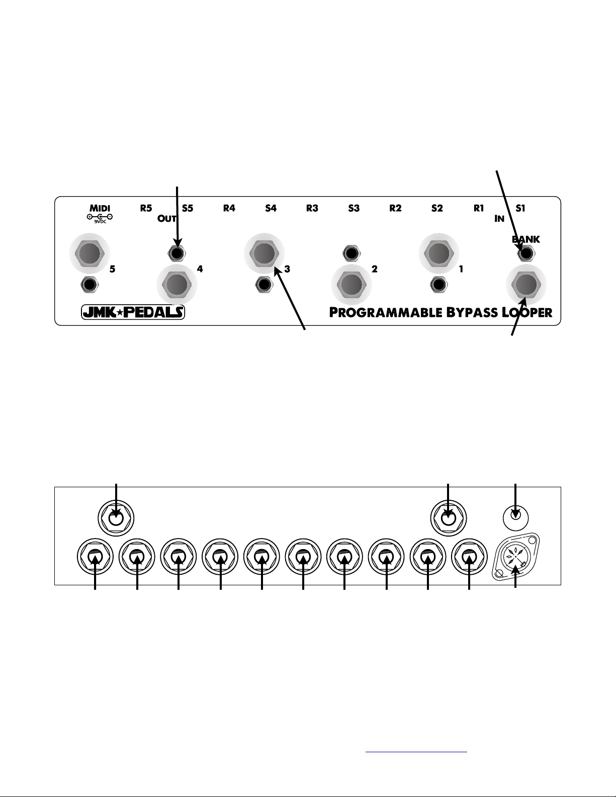
Programmable Bypass Looper Diagrams
Loop Bypass/Preset
LEDs
Top Panel
Loop Bypass/Preset
switches
Bank/Program LED
Bank/Program Switch
Back Panel
Input Jack
S1 S2 S3 S4 S5R1 R2 R3 R4 R5
Loop Jacks
Output Jack DC Jack
Midi Output
Jack
S = Send
R = Return
This Document is designed for personal use only! Do not post this document online or use this to create a
product for sale without permission of itʼs owner: [email protected]
Page 3
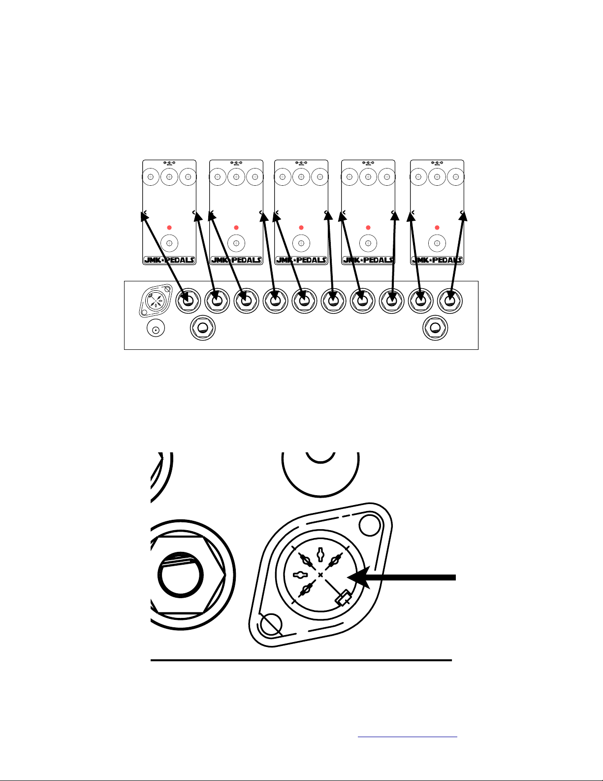
How to setup your Programmable Bypass Looper
Step One: Each Loop has a Send and Receive jack. Use a patch cord to connect
•
each Send Jack of each loop to the input of each pedal you want in the loops. Use
more patch cords to connect the Receive Jack of each loop to the output of pedal
that corresponds. Make sure each Pedal is active. (There is no rule that requires
the user to put only one effect in a loop)
Step Two: Connect the Midi Output Jack to the Midi Input Jack of any pedal you
•
wish to control via Midi using a typical 5 pin Midi cable. If you want to control
multiple pedals, you must use the Midi Output Jack of the first device you have
connected to and connect each subsequent device in Series. (This step is optional)
This Document is designed for personal use only! Do not post this document online or use this to create a
product for sale without permission of itʼs owner: [email protected]
Page 4
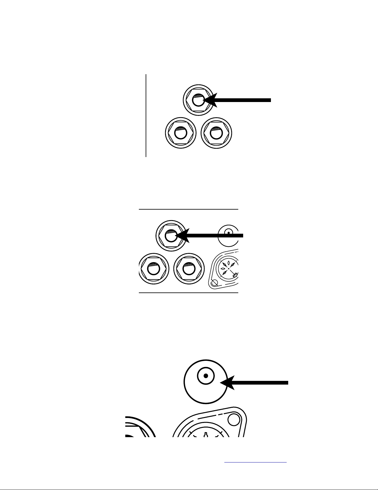
Step Three: Plug your instrument signal into the Input Jack of the Programmable
•
Bypass Looper. You can directly connect your instrument (Guitar, Bass, Etc.) to the
Programmable Bypass Looper, or you can connect from another pedal or device
used inline. The Programmable Bypass Looper does not need to be first in the
signal chain.
Step Four: Plug the Programmable Bypass Looperʼs Output into the next device
•
you want to in your signal chain. This could be another pedal or device, or it could
be an amplifier or DI box sent to FOH.
Step Five: Connect the proper power to each pedal being used, including the
•
Programmable Bypass Looper. The Programmable Bypass Looper requires a
power supply of 9V DC, and uses a tip negative polarity. It is recommended to use
a power supply that supplies 400mA of current or more.
This Document is designed for personal use only! Do not post this document online or use this to create a
product for sale without permission of itʼs owner: [email protected]
Page 5

How to Operate the Programmable Bypass Looper
Once the Looper is setup, your instrument is plugged in, and your amplifier is turned on,
you will need to learn to use the Programmable Bypass Looper. Weʼve done our best to
make itʼs operation is as intuitive and simple as possible. There are a few key features
that you will need to understand.
The Bank switch cycles through the Banks. On powering the unit, the
•
Programmable Bypass Looper will default into Manual Mode. Each time you press
the Bank switch, you cycle up into a new Bank: pressing once will move you from
from Manual Mode to Preset Bank A, pressing the Bank switch again will move you
from Preset Bank A to Preset Bank B, and so on. Once reaching Preset Bank D,
pressing the Bank Switch will send you from Preset Bank D back to Manual Mode
again. As you select each mode, the Bank LED changes to one of five different
colours.
The Bank switch also functions as the Programming Switch. Each of the 20
•
available presets can be programmed to utilize a combination of the effects you
have plugged into the Programmable Bypass Looper. When in Programming
Mode, the Bank LED will blink. In Manual Mode, there is no programming or Midi.
In Manual Mode, each Loop switch functions as an on/off switch for each Loop,
•
essentially letting the Programmable Bypass Looper function as a high quality,
relay based, true bypass looper.
In each Preset Bank, each Loop switch now functions as a Preset Selection switch,
•
with each switch working to turn off the previous preset, and turn on the new preset
Each Loop LED is a bi-colour LED, which means that when a loop is active, the
•
LED will be one colour, and when a Preset is selected, the LED will be another
colour, and when both a loop is active and a preset is selected using the same
switch, the LED will a combination of those first two colours.
How to Program a Preset In a Preset Bank
Select a Bank in which to program a Preset
•
Select a Preset switch to be programmed. A Preset may already be programmed,
•
or it may be blank. A preset must be selected to program, and the selected preset
will be the one that is programmed.
Hold the Bank switch for approximately 3 seconds to enter program mode
•
Use the 5 Loop switches to determine which loops are turned off or on. Each loop
•
LED will be turned off or on to reflect the loopʼs off or on status.
Hold the Bank switch for approximately 3 seconds to Save your preset.
•
To Exit Program Mode, simply hold the Bank switch for approximately 3 seconds.
•
This will also save your preset at the same time.
This Document is designed for personal use only! Do not post this document online or use this to create a
product for sale without permission of itʼs owner: [email protected]
Page 6
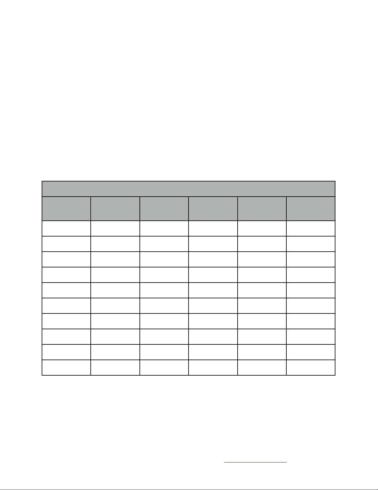
Using the Midi Output
Preset PC Message Change List
Bank
Preset PC Message Change List
Preset
Midi
Program
Bank
Preset
Midi
Program
AAAAABBBBB1
001C1
0112002C2
012
3
003C3
013
4
004C4
014
5
005C5
015
1
006D1
016
2
007D2
017
3
008D3
018
4
009D4
019
5
010D5
020
Using the Midi Output of the Programmable Bypass Looper will allow you to utilize the
Midi functions of any effects you utilize. Here is some useful info to help you understand
how this functions:
First, ensure that the Midi Output of the Programmable Bypass Looper is
•
connected via a 5 pin Midi Cable to the Midi Input of whatever effect you desire to
control.
Select a Preset Bank via the Bank switch.
•
As you choose a Preset from the Bank you are currently in, A Midi Program
•
Change (PC) message is sent via your Midi Cable.
When you select a new Preset, either from the Bank youʼre currently in or in
•
another Bank, a new PC Message will be sent to your Midi connected unit.
** Please Note: Midi Devices often start with Program 000, so keep in mind that your
Preset saved in the first slot in the effect device memory bank might get skipped.
This Document is designed for personal use only! Do not post this document online or use this to create a
product for sale without permission of itʼs owner: [email protected]
Page 7
Setting the Midi Output ChanneL
Midi Channel
Dip Switch 1
Dip Switch 2
Dip Switch 3
Dip Switch 4
12345678910111213141516off
off
off
offonoff
off
off
offonoff
offonon
off
off
off
off
offonon
off
offonoffonoffonononoffonoff
offonoffonoffonoff
offonon
offonononoff
off
offonononoffonon
offonononononon
on
In order to send a Program Change message via Midi, you need to make sure that the
midi device you are trying to change and the device you are controlling it with (the
Programmable Bypass Looper for example) are using the same Midi Channel. There is
a potential for 16 different channels of midi communication, and you can set your
Programmable Bypass Looper to ʻspeakʼ on any of those 16 different channels. Hereʼs a
description on how to set your channel:
This Document is designed for personal use only! Do not post this document online or use this to create a
product for sale without permission of itʼs owner: [email protected]
Page 8

Bypass/Switching with Loop Five
There are two ways to set up loop five to operate:
Loop five can operate in ʻLoop Modeʼ as a normal true bypass loop, just as loops
•
one through four would operate
Loop five can operate in ʻSwitching Modeʼ as a switching device typically used for
•
toggling an amp channel, or reverb, or some other device or function which utilizes
a remote switch.
Keep in mind that when in ʻSwitching Modeʼ instead of ʻLoop modeʼ that the signal
passes from loop four to the output. This means that you can still use the first four loops
in the standard format, and simply control your switched device as needed.
While in ʻSwitching Mode,ʼ the two jacks for loop five change from ʻsendʼ and ʻreturnʼ to
the following function:
The Send Jack is ʻopen,ʼ meaning that the tip of the jack is disconnected from
•
Ground when the switch is off. When the switch is turned on, the send jack
becomes ʻclosed,ʼ meaning that the tip of the jack is connected to ground.
The Return Jack operates in reverse from the send jack. The Return jack is
•
ʻclosedʼ when the switch is off, and is ʻopenʼ when the switch is on.
Consult your device or amp for the required switching scheme needed to determine if
the Programmable Bypass Looper is capable of handling your switching needs, and
which jack to utilize. Currently, TRS switching jacks are not supported, so keep that in
mind if when using this element of the Programmable Bypass Looper.
Setting Loop five for Switching or bypass
Setting loop five for Switching or Bypass simply requires 3 shunts, which connect three
sets of two pins on the 2x4 pin header located on the Audio Board. They need to be set
in one of the following configurations:
Switching Bypass
This Document is designed for personal use only! Do not post this document online or use this to create a
product for sale without permission of itʼs owner: [email protected]
 Loading...