

Page 1
MÁQUINA DUPLICADORA ECCO PLUS
Manual de instrucciones
KEY CUTTING MACHINE ECCO PLUS
Instruction manual
KOPIERMASCHINE ECCO PLUS
Anweisungshandbuch
MACCHINA DUPLICATRICE ECCO PLUS
Manuale d’istruzione
MACHINE A TAILLER LES CLES ECCO PLUS
Notice d'utilisation
MÁQUINA DUPLICADORA ECCO PLUS
Manual de instruções
Page 2
Indice / Index / Inhaltsverzeichnis / Indice / Index / Indice
1. Presentación y aspectos generales
1-1 Generalidades 3
1-2 Transporte y embalaje 3
1-3 Etiqueta identificadora 3
2. Características de la máquina
2-1 Nomenclatura de la llave 3
2-2 Elementos principales de la máquina 3
2-3 Datos técnicos 3
2-4 Componentes y partes funcionales 4
3. Operatividad y funcionamiento
3-1 Reglaje máquina 4
3-2 Operación de duplicado de llave 5
4. Mantenimiento y seguridad
4-1 Cambio de fresa o del cepillo 5
4-2 Recomendaciones de seguridad 5
5. Figura
1. Presentation and general aspects
1-1 General points 6
1-2 Transport and packing 6
1-3 Identification label 6
2. Caracteristics of the machine
2-1 Parts of a key 6
2-2 Main elements of the machine 6
2-3 Technical information 6
2-4 Components and funtional parts 7
3. How the machine works
3-1 Machine adjustment 7
3-2 Key cutting operation 8
4. Maintenance and safety
4-1 Changing the milling cutter 8
4-2 Safety recommendations 8
5. Figure
3
3-4
4-5
5
21-22
6
6-7
7-8
8
21-22
1. Presentazione e aspetti generali
1-1 Generalita’ 12
1-2 Trasporto e imballaggio 12
1-3 Targhetta d´identificazione 12
2. Caractteristiche della macchina
2-1 Identificazione della chiave 12
2-2 Elementi principali della macchina 12
2-3 Dati tecnici 12
2-4 Accessori e parti funzionali della macchina 13
3. Operativitá e funzionamento
3-1 Regolazione della macchina 13
3-2 Duplicazione della chiave 14
4. Manutenzione e sicurezza
4-1 Cambio della fresa e della spazzola 14
4-2 Raccomandazioni di sicurezza 14
5. Figura
1. Presentation et aspects generaux
1-1 Generalites 15
1-2 Transport et emballage 15
1-3 Plaque signaletique 15
2. Caracteristiques de la machine
2-1 Nomenclature de la clé 15
2-2 Elements principaux de la machine 15
2-3 Donnees techniques 15
2-4 Composants et parties fonctionnelles 16
3. Fonctionnement
3-1 Reglage de la machine 16
3-2 Reproduction de cles 17
4. Maintenance et securite
4-1 Remplacement de la fraise ou de la brosse 17
4-2 Recommandations de securite 17
5. Figure
12
12-13
13-14
14
21-22
15
15-16
16-17
17
21-22
1. Vorstellung und grundlegende begriffe
1-1 Allgemeines 9
1-2 Transport und verpackung 9
1-3 Typenschild 9
2. Eigenschaften der maschine
2-1 Nomenklatur des schlüssels 9
2-2 Hauptbestandteile der maschine 9
2-3 Technische daten 9
2-4 Komponenten und funktionsbauteile 10
3. Betriebsfähigkeit und funktionsweise
3-1 Einstellung der maschine 10
3-2 Schüsselkopiervorgang 11
4. Wartung und sicherheit
4-1 Fräserwechsel 11
4-2 Sicherheitsempfehlungen 11
5. Abbildung
9
9-10
10-11
11
21-22
1. Apresentação e aspectos gerais
1-1 Generalidades 18
1-2 Transporte e embalagem 18
1-3 Etiqueta identificadora 18
2. Características da máquina
2-1 Nomenclatura da chave 18
2-2 Elementos principais da máquina 18
2-3 Dados tecnicos 18
2-4 Componentes e partes funcionais 19
3. Operação e funcionamento
3-1 Regulação da máquina 19
3-2 Duplicação de chaves 20
4. Manutenção e segurança
4-1 Mudança de fresa ou de catrabuxa 20
4-2 Recomendações de segurança 20
5. Figura
18
18-19
19-20
20
21-22
Page 3
1
Presentation
and general aspects
2
Characteristics
of the machine
English
General points
1.1
The ECCO PLUS key cutting machine has been designed
taking into account the safety standards currently in
force in the EU.
Although the machine is not difficult to install, it is best
not to try to install, adjust or use it without having first
read this manual.
The machine leaves our factory ready for use and only
requires the carrying out of calibration operations for
the tools that are going to be used.
Transport and packing
1.2
The machine comes packed in packing of the following
size:
Width = 570 mm, length = 520 mm, height = 410mm
Machine weight plus packing = 20 Kg.
When the machine has been unpacked, check carefully
to see if it has suffered any damage during transportation. If you find any problems, please inform the carrier
immediately and do not do anything with the machine
until the carrier’s agent has carried out an inspection.
Identification label
1.3
The ECCO PLUS key cutting machine has an identification label, giving the serial number, the name and
address of the manufacturer, the CE mark and the year
of manufacture.
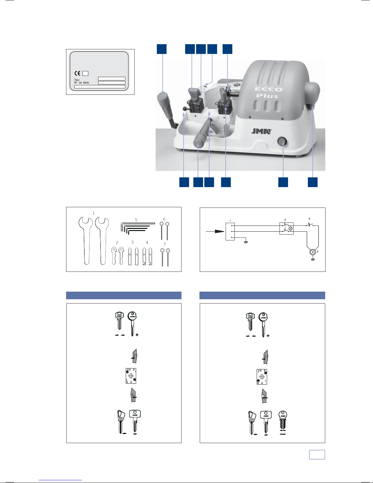
See figure 1
The ECCO PLUS machine is a robust and precise manual
machine for cutting flat cylinder lock keys, vehicle keys,
cross-shaped keys and special keys.
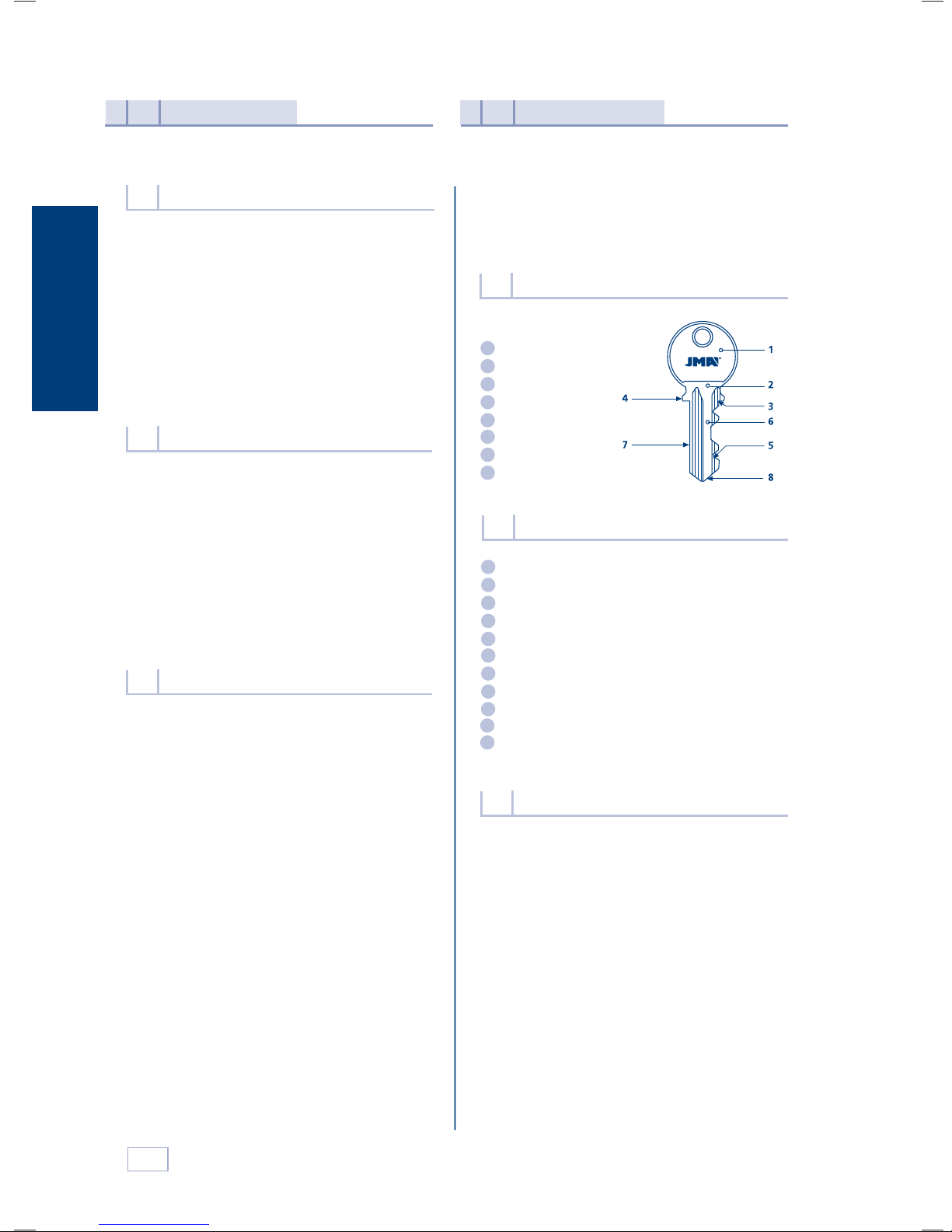
Parts of a key
2.1
1
Head
2
Neck
3
Top shoulder
4
Bottom shoulder
Teeth
5
6
Blade
Back
7
Tip
8
Main elements of the machine
2.2
Milling cutter
1
2-sided clamp
2
Clamp handle
3
Slide
4
Slide handle
5
6
Fold-away stop
Tracer point
7
8
Start switch
9
Tracer point adjustment control
10
Plane
11
Slide advance lever
See Figure 2
6
Technical information
2.3
The main technical information is as follows:
Motor: Single phase 220V, 50Hz, 0.18Kw,1500 rpm, 1.7 Amp.
or Single phase 110V, 60Hz,0.18Kw, 1800 rpm 3.14 Amp.
Milling cutter: Extra quick speed steel Ø63 x 16 x5 mm.
Speed: 1.500 rpm.
Clamps: 2 sided.
Displacement: On self-lubricated bearings.
Effective travel: X axis = 70 mm.
Dimensions: Width = 530 mm, Depth = 245 mm,
Height = 280 mm.
Weight: 16,5 Kg.
Page 4

3
How the machine
works
Components and functional parts
2.4
2.4.1 Accesories See Figure 3
1
Size 18 spanner.
Keys to adjust the height and depth of the
2
teeth.
3
Wedges to adjust the tip of the key.
4
Recessed wedges to cut cross-shaped keys.
5
Set of allen keys (2, 2.5, 3, 4, 5).
2.4.2 Electric circuit See Figure 4
The main components of the electric circuit and
the electronic components are as follows:
1
Socket
2
Start switch
3
Motor
4
Microswitch
2.4.3 2-sided clamp See Figure 5
The clamp is designed to secure a different family
of keys on each side. The figure shows the possibilities for cutting on each side of the clamp.
1) Cutting the key with support on the back:
- Keys with normal blade
- Keys with narrow blade
2) Cutting by means of clamping the key by the
guide (profile).
Machine adjustement
3.1
3.1.1 Control and adjustment of the side distance
• Place the two adjustment keys (1) in the clamps, so
that the head of the adjustment key rests against
the inner stop of side 1 or 2 of the clamp.
• Then tighten the clamps.
• Move the clamps with the adjustment keys (1)
towards the tracer point (I) and the milling cutter
(F), so that the adjustment keys are in the correct
position in respect of the tracer point and milling
cutter. This is done by moving the slide backwards
and keeping it in that position with the help of
the handle (M), moving the slide to the right with
the help of the arm (B), thereby releasing the
slide, and then moving the slide gently over the
tracer point (I) and milling cutter (F).
• If the grooves of the adjustment key do not coin-
cide properly with the tracer point and the milling
cutter, proceed as follows:
• By gently loosening the shaft screws (T), you will be
able to move the milling cutter to the right or left.
You have to move the milling cutter to a position in
which it coincides with the groove of the corresponding adjustment key. To carry out this operation,
you have to remove the motor guard first.
• The distance is now perfectly adjusted, with the
tracer point and milling cutter coinciding with the
respective recesses of the adjustment keys. Now
tighten the shaft screws (T).
See Figure 6
3.1.2 Control and adjustment of the cutting depth
• Place the two adjustment keys (1) in the clamps, so
that the head of the adjustment key rests against
the inner stop of side 1 or 2 of the clamp..
• Move the clamps with the adjustment keys (1)
towards the tracer point (I) and the milling cutter
(F), so that the adjustment keys rest on the tracer
point and the milling cutter. The machine slide can
be released in the following way: move the slide
backwards and keeping it in that position with the
help of the lever (M), move the slide to the right,
with the help of the arm (B). To lock the slide again,
reverse the process, with the slide midway along
its travel. Move the slide back with the help of the
handle (M) and keeping it in that position, move
the slide to the left with the help of the arm (B).
With the slide as far to the left as possible, gently
release the slide so that it becomes locked.
• Turn the milling cutter by hand. If it gently rubs the
adjustment keys, the machine is properly adjusted.
• If the milling cutter turns freely, without rubbing,
this indicates that it is to far back in respect of the
tracer point and is not cutting deeply enough. On
the other hand, if the milling cutter becomes jammed up against the adjustment key, this indicates
that it is too far forward in respect of the tracer
point and is cutting too deeply.
• If either of these situations should occur, proceed as
follows:
- Undo the screw (L) securing the tracer point (I)
and turn the micrometric screw (H). See Figure 7.
- Move the tracer point forwards or backwards
until the milling cutter turns freely and rubs
English
7
Page 5

4
Maintenance and
safety
English
gently against the adjustment key. Then tighten the tracer point screw (L).The machine is
now in perfect working order.
Key cutting operation
3.2
• Insert the original key into the left-hand clamp, keeping
it a distance of 2 to 3 mm from the edge of the clamp.
See Figure 8.
• Tighten up the clamp, keeping the back of the key pro-
perly pressed against the base of the clamp.
• Insert the key blank to be cut into the right-hand clamp
and, before tightening up the clamp, raise the gauge (C)
and align the two keys. Ensure that the two pointers of
the gauge are resting firmly up against the top shoulders of both keys. Finally, tighten up the clamps.
• Both the original key and the key blank to be cut should
be inserted in the left-hand side of the respective clamps.
• Withdraw the gauge (C). Start the machine and release
the slide (as explained in point 3.1.2). Move the keys
towards the tracer point (I) and the milling cutter (F).
• Remember that you have to work from left to right. Rest
the original key against the tracer point and start to work,
moving the slide from right to left, using the arm (B),
ensuring that the pressure exercised on the tracer point is
that required by the spring that acts on the slide shaft.
• Once the key has been cut, return the slide to its initial
position, as explained in chapter 3.1.2. Then remove the
keys by undoing the clamps.
• If the key cutting operation has left any burrs on the
cut key, these can be removed with the plane that the
machine has been fitted with for this purpose.
3.2.1 Duplication of narrow bit key. Use of rods
1.2 and 1.7
The rods are inserted between the bottom of the
clamp and the back of the key when the key to be
duplicated has a narrow bit. The rods prevent contact
with the clamp itself by making the key protrude
further. See Figure. 9
3.2.2 Cutting keys without shoulders
When carrying out maintenance operations, the following requirements must be met:
Never carry out any maintenance operation with the
1
machine switched on.
2
Unplug the machine.
3
The indications in this manual must be strictly adhered to.
4
Use original spare parts.
Changing the milling cutter
4.1
Undo the two milling cutter guard screws and remove
the guard.
To change the milling cutter: With the help of the two
size 18 spanners, lock the milling cutter shaft and undo
the nut (K) – left-hand thread – securing the milling cutter (F). Then replace the milling cutter and finally put the
milling cutter guard back into place. See Figure.12.
To change the plane: Lock the milling cutter shaft with
the help of a size 18 spanner. Undo the screw (R) with
the help of an allen key. Replace the plane and finally
put the milling cutter guard back into place.
Safety recommendations
4.2
1
Do not try and start or handle the machine until all
safety matters, installation instructions, operator guides and maintenance procedures have been fulfilled
and understood.
2
Always switch off the power supply before carrying
out any cleaning or maintenance operation.
3
Always keep the machine as well as its surroundings
clean.
4
Work with dry hands.
5
Use safety glasses, even if the machine is fitted with
guards.
6
Ensure that the machine is earthed.
Insert the two wedges (2) (see Figure.10) into the
vertical slots (R) of each clamp, depending on the
length of the key to be cut.
Rest the tips of the keys against the wedges (2).
The keys are now adjusted. Then tighten up the
clamps. Before starting to cut the key, it is advisable to remove the wedges.
3.2.3 Cutting cross-shaped keys.
Side 1 of the clamp
This type of key must be inserted into the clamps from
left to right. Place the wedges (5) (see Figure.11) with
the opening or recess facing upwards, in one slot or the
other (R), depending on the length of the key to be cut.
The teeth of the key can be cut in three operations,
by turning and locking the shoulder of the key against
the wedge (5) each time.
8
Page 6
ALEJANDRO ALTUNA, S.A.
Bidekurtzeta, 6
20500 MONDRAGON
(Guipuzcoa) Spain
Figura 1 / Figure 1 / Abbildung 1
711 9
13
Figura 3 / Figure 3 / Abbildung 3
Standard Portugal
2456
Figura 2 / Figure 2 / Abbildung 2
Figura 4 / Figure 4 / Abbildung 4
8 10
Figura 5 / Figure 5 / Abbildung 5
21
Page 7
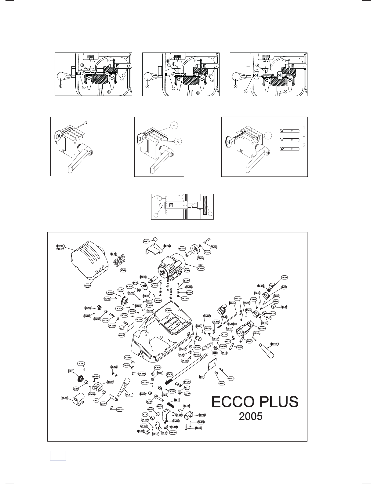
Figura 6 / Figure 6 / Abbildung 6 Figura 7 / Figure 7 / Abbildung 7 Figura 8 / Figure 8 / Abbildung 8
F
K
R
Figura 9 / Figure 9 / Abbildung 9
Figura 10 / Figure 10 / Abbildung 10
Figura 12 / Figure 12 / Abbildung 12
Figura 11 / Figure 11 / Abbildung 11
22
Page 8

Bidekurtzeta, 6. Apdo. 70
20500 Arrasate-Mondragón
(Gipuzkoa) ESPAÑA
Tel. + 34 943 79 30 00 / 943 79 33 32
Fax. + 34 943 79 72 43
www.jma.es
e-mail:[email protected]
 Loading...