

Page 1
Page 2

Indice / Index / Inhaltsverzeichnis / Indice / Index / Indice
1. Presentación y aspectos generales
1.1 Generalidades 4
1.2 Transporte y embalaje 4
1.3 Etiqueta identificadora 4
2. Características de la máquina
2.1 Elementos principales de la máquina 4
2.2 Datos técnicos 4
2.3 Componentes y partes funcionales 4-5
2.3.1 Circuito eléctrico 4
2.3.2 Mordazas 4
2.3.3 Bloqueo del carro en el eje “ X “ 4
2.3.4 Palpado elástico o bloqueo 5
2.3.5 Regulación vertical del palpador 5
2.3.6 Cambio de fresa y palpador 5
2.3.7 Accionamiento del motor 5
3. Operatividad y funcionamiento
3.1 Regulacion y puesta a punto 6
3.1.1 Ajuste de la profundidad de corte 6
3.1.2 Flexibilidad del palpador 6
3.2 Duplicado de llaves 6
3.2.1 Duplicado de la llave SEA-1 6
3.2.2 Duplicado de las llaves tipo OP-WH.P y OP-WY.P 6
3.2.3 Llaves tipo ME-3.P y ME-4.P 6
3.2.4 Llave JIS-4.P 6
3.2.5 Laves WIN-1D, WIN-2D, WIN-3D y WIN-4D 6
3.2.6 Llaves KABA 7
3.2.7 Llave tipo FO-6.P 7
4. Mantenimiento y seguridad
4.1 Sustitucion de la correa 8
4.2 Sustitucion de los fusibles 8
4.3 Recomendaciones de seguridad 8
4-5
6-7
4
1. Einleitung und allgemeine hinweise
13
1.1 Allgemeines 13
1.2 Transport und verpackung 13
1.3 Typenschild 13
2. Merkmale der maschine
13-14
2.1 Wichtigste maschinenteile 13
2.2 Technische daten 13
2.3 Komponenten und funktionsteile 13-14
2.3.1 Elektrokreislauf 13
2.3.2 Pannbacken 13
2.3.3 Blockieren des Schlittens auf der X-Achse 13
2.3.4 Blockierter oder elastischer Kopiertaster 14
2.3.5 Vertikaleinstellung des Kopiertasters 14
2.3.6 Austausch von Fräser und Kopiertaster 14
2.3.7 Einschalten des Motors 14
3. Betriebsfähigkeit und funktionsweise
15-16
3.1 Regulierungen und einrichten 15
3.1.1 Einstellen der Schnitttiefe 15
3.1.2 Flexibilität des Kopiertasters 15
3.2 Kopieren von schlüsseln 15
3.2.1 Kopieren des SEA-1 Schlüssels 15
3.2.2
Kopieren von Schlüsseln des Typs OP-WH.P und OP-WY.P
15
3.2.3 Schlüssel des Typs ME-3.P und ME-4.P 15
3.2.4 Schlüssel JIS-4.P 15
3.2.5
Schlüssel des Typs WIN-1D, WIN-2D, WIN-3D und WIN-4D
15
3.2.6 KABA-Schlüssel 16
3.2.7 Schlüssel des Typs FO-6.P 16
8
4. Wartung und sicherheit
17
4.1 Austausch des riemens 17
4.2 Austausch der sicherungen 17
4.3 Sicherheitshinweise 17
5. Accesorios para cortar diferentes modelos de llaves
1. Presentation and general aspects
1.1 General points 9
1.2 Transport and packaging 9
1.3 Identifying label 9
2. Machine characteristics
2.1 Main elements of the machine 9
2.2 Technical data 9
2.3 Components and functional parts 9-10
2.3.1 Electrical circuit 9
2.3.2 Clamps 9
2.3.3 Carriage lock on X-axis 9
2.3.4 Flexible tracing or locking 10
2.3.5 Vertical tracer point adjustment 10
2.3.6 Changing the milling cutter and tracer point 10
2.3.7 Motor operation 10
3. Operation and adjustment
3.1 Regulation and adjustment 11
3.1.1 Adjusting the cutting depth 11
3.1.2 Tracer point flexibility 11
3.2 Cutting keys 11-12
3.2.1 Cutting SEA-1 keys 11
3.2.2 Cutting OP-WH.P and OP-WY.P type keys 11
3.2.3 ME-3.P and ME-4.P type keys 11
3.2.4 JIS-4.P keys 11
3.2.5 WIN-1D, WIN-2D, WIN-3D and WIN-4D keys 11
3.2.6 KABA keys 12
3.2.7 FO-6.P type keys 12
4. Maintenance and safety
4.1 Replacing the belt 12
4.2 Replacing the fuses 12
4.3 Safety recommendations 12
5. Accessories for cutting different models of keys
30-33
9
9-10
11-12
12
30-33
5. Fräszubehör für einige schlüsselmodelle
1. Presentazione ed aspetti generali
1.1 Generalita' 18
1.2 Trasporto e imballaggio 18
1.3 Targhetta identificativa 18
2. Caratteristiche della macchina
2.1 Elementi principali della macchina 18
2.2 Dati tecnici 18
2.3 Componenti e parti funzionali 18-19
2.3.1 Circuito elettrico 18
2.3.2 Morsetti 18
2.3.3 Blocco carrello sull’asse X 18
2.3.4 Tastatore bloccato o flessibile 19
2.3.5 Regolazione verticale del tastatore 19
2.3.6 Cambio della fresa e del tastatore 19
2.3.7 Interruttori 19
3. Operativita' e funzionamento
3.1 Regolazioni e taratura 20
3.1.1 Regolazione della profondità di taglio 20
3.1.2 Flessibilità del tastatore 20
3.2 Duplicazione delle chiavi 20
3.2.1 Duplicazione chiave SEA-1 20
3.2.2 Duplicazione delle chiavi OP-WH.P e OP-WY.P 20
3.2.3 Duplicazione delle chiavi ME-3.P e ME-4.P 20
3.2.4 Duplicazione chiavi JIS-4D 20
Duplicazione chiavi WIN-1D, WIN-2D, WIN-3D e WIN-4D
3.2.5
20
3.2.6 Duplicazione delle chiavi KABA 21
3.2.7 Duplicazione chiavi FO-6P 21
4. Manutenzione e sicurezza
4.1 Sostituzione della cinghia 21
4.2 Sostituzione dei fusibili 21
4.3 Raccomandazioni di sicurezza 21
5. Accessories for cutting different models of keys
30-33
18
18-19
20-21
21
30-33
Page 3

1
Presentation
and general aspects
2
Machine
Characteristics
General points
1.1
The DAKKI key cutting machine has been designed
taking into account the safety standards currently in
force in the EEC.
The safety of the persons operating this type of machine can only be guaranteed by means of a correctlydesigned personal safety programme, implementing
a maintenance programme and following the advice
recommended, and compliance with the safety standards indicated in this manual.
Although machine installation is a simple process, this
manual should be carefully read before installing, adjusting and using it.
The machine leaves our factory ready for use and only
requires calibration of the tools to be used.
Transport and packaging
1.2
The DAKKI machine is supplied in a strong cardboard
box, protected with packing foam and with the following dimensions:
Width = 520 mm; Height = 650 mm; Depth = 575 mm
Weight of machine with packaging = 23 Kg.
On unpacking the machine, check whether it has suffe-
red any damage during transportation.
If you should observe any problems, inform the carrier
immediately and do not use the machine until it has
been inspected by the carrier’s agent.
To move the machine, we recommend picking it up by
its base only, and not by any other part.
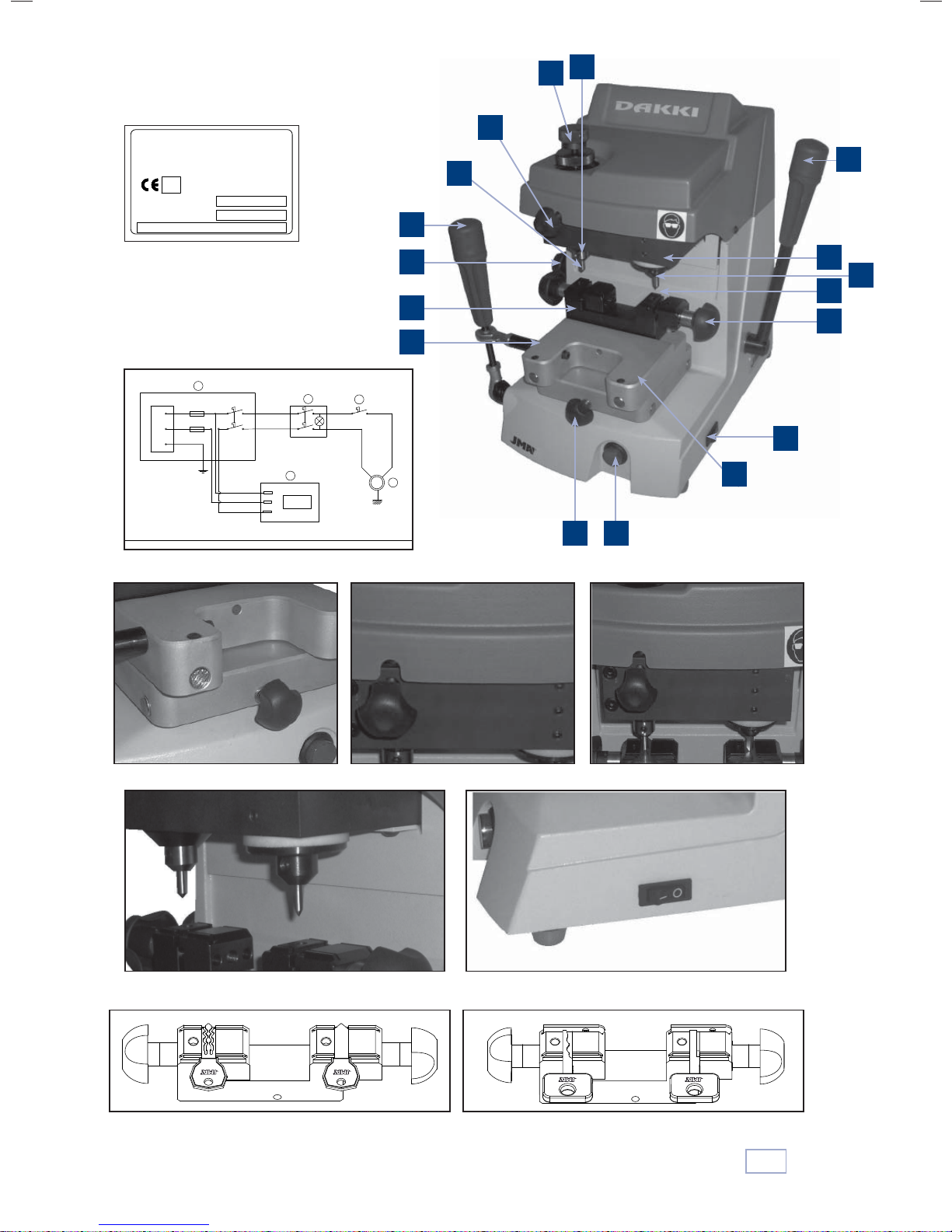
1.3
Identification label
The DAKKI key cutting machine has an identification
label specifying the serial or registration number of the
machine, the name and address of the manufacturer,
the EC conformity mark and the year of manufacture.
See figure 1
The DAKKI machine is an accurate, robust key cutting
machine with an interchangeable clamp enabling duplication of a large range of key types.
Main elements of the machine
2.1
1.-Clamp holder carriage (X- and Y-axes)
1
2.-Head (Z-axis)
2
3.-Clamp
3
4
4.-Clamp opening/closing knob
5.-Clamp holder carriage locking knob (X-axis)
5
6
6.-Head blocking knob (Z-axis)
7
7.-Tracer point locking knob (fixed/springing)
8
8.-Tracer point adjustment wheel
9
9.-Carriage drive lever (X- and Y-axes)
10
10.- Head drive lever (Z-axis)
11
11.- Milling cutter holder head
12
12.- Tracer point holder head
13
13.- Milling cutter
14
14.- Tracer point
15
15.- Master switch
16
16.- Start-up switch
17
17.- Motor switch
Technical data
2.2
Motor: Single phase 200 W, 230 V - 50 Hz; (Optional: Single
phase 200W, 110V – 60Hz)
Milling cutter: High-speed steel (HSS)
Milling cutter speed: 5500 r.p.m.
Clamps: Interchangeable
Displacement: Guided by ground shafts
Effective travel: X-axis = 32 mm; Y-axis = 40 mm; Z-axis = 27 mm
Dimensions: Height = 378 mm; Width = 270 mm; Depth = 340 mm
Weight: 18 Kg
Components and functional parts
2.3
See figure 2
2.3.1 Electrical circuit See figure 3
The main components of the electrical and electronic
circuit are as follows:
Mains connection: With fuses and a master
1
switch.
2
Connection plate: Base for connections.
Start-up switch: Visible luminous switch for
3
starting up the machine.
4
2-way switch: Start/stop.
Motor: Single phase brush motor.
5
English
2.3.2 Clamps
The standard machine is supplied with a universal clamp,
interchangeable with any of the optional clamps, which
are specially designed so that this machine can duplicate
a wider range of key families.
2.3.3 Carriage lock on X-axis See figure 4
The X-axis lock is used for straight-line milling or pointing,
in the direction of the Y-axis.
To lock and unlock the carriage in this direction, turn the
corresponding knob.
99
Page 4

2.3.4 Flexible tracing or locking See figure 5
The tracer point is the axis protruding from the left side of
the machine head, seen from the front. This tracer point
has two operating modes, depending on the work to be
carried out:
Flexible tracer point: With the flexible tracer
1
point, key cutting is performed with vertical
advance (Z-axis). Duplication by points.
2
English
Tracer point locked: With the tracer point locked,
key cutting is performed with horizontal advance
(X- and Y-axes).
To switch from “tracer point locked” to “flexible tracer
point”, simply loosen the corresponding knob. To switch
from “flexible tracer point” to “tracer point locked”, push
the tracer point upwards manually and when it reaches its
limit, lock it in place with the corresponding knob.
2.3.5 Vertical tracer point adjustment See Figure 6
Place the two keys in the clamps (the original key in the
left-hand clamp and the key to be cut in the right-hand
clamp).
Make the adjustment as follows:
• Place the tracer point in “tracer point locked” operating mode.
• Lower the head and rest the tools on a flat part of the
key, without pressing down.
• When the tools make contact with the keys, there are
three possibilities
The milling cutter and the tracer point make con-
1
tact with their respective keys at the same time.
This means the machine is correctly adjusted.
2
The tracer point makes contact with the key, but
the milling cutter does not.
If this situation occurs, the vertical position of the
tracer point needs to be adjusted, raising the tracer point. This is done as follows:
- Place the tracer point in “flexible tracer point”
operating mode.
- Lower the head and rest the tools on a flat part
of the key, without pressing down.
- Unlock the tracer point depth adjustment wheel
and turn it anti-clockwise until the milling cutter
and the tracer point make contact with their
respective keys at the same time.
- In this position, lock the adjustment wheel using
its locking nut.
3
The milling cutter makes contact with the key,
but the tracer point does not.
If this situation occurs, the vertical position of
the tracer point needs to be adjusted, lowering
the tracer point. This is done as follows:
- Place the tracer point in “flexible tracer point”
operating mode.
- Lower the head and rest the tools on a flat part
of the key, without pressing down.
- Unlock the tracer point depth adjustment wheel
and turn it clockwise until the milling cutter and
the tracer point make contact with their respective keys at the same time.
- In this position, lock the adjustment wheel using
its locking nut.
2.3.6 Changing the milling cutter and tracer point
See figure 7
To release the milling cutter, simply loosen the
•
two setscrews on the milling cutter holder shaft
and remove it. Insert the new milling cutter,
making sure it reaches its limit.
• To release the tracer point, simply loosen the sets-
crew on the tracer point holder shaft and remove
it. Insert the new tracer point, making sure it
reaches its limit.
2.3.7 Motor operation See figure 8
• On the right side of the machine there is a two-
way switch (0/I) for activating the milling cutter
rotation speed:
- 0 > Milling cutter off
- I > Milling cutter rotating
10
Page 5

3
Operation
and functioning
Regulation and adjustment
3.1
3.1.1 Adjusting the cutting depth
• This adjustment is to be made each time the milling
cutter and tracer point are changed.
• The procedure for making this adjustment is detai-
led in point “2.3.5” of this manual.
3.1.2 Tracer point flexibility
• The tracer point can be positioned below its adjust-
ment position, when it is in flexible mode.
• This tracer point location enables the milling cutter
descent to be guided during the key cutting operation. The tracer point is gradually inserted in each
of the holes in the original key to be duplicated.
When the tracer point is inserted in its corresponding hole, the milling cutter has not yet begun to
machine they key. When the milling cutter begins
to cut the key, the machine head is guided by the
tracer point, thus preventing the milling cutter
from accidentally going off course.
• The functioning of this system is explained in point
2.3.4 of this manual.
Cutting keys
3.2
For safety during the cutting operation, the following
points must be observed:
1
Always work with dry hands.
Ensure the earth is connected.
2
Wear protective goggles.
3
All key clamping and releasing operations must be
4
done with the machine switched off.
3.2.1 Cutting SEA-1 keys
• Milling cutter and tracer point F-1 / P-1 are used for
cutting the side points of the keys, and the points
are cut normally.
• Milling cutter and tracer point F-3 / P-3 are used for
cutting the grooves in the key blade. The grooves
are cut as follows:
- Adjust the heights of the milling cutter and tracer
point, and take the tracer point out of flexible
mode.
- Lower the tracer point slightly by turning the
corresponding adjustment wheel (around 1/10 of
a turn).
- Insert the tracer point in the groove in the key
blade and lock the machine head.
- Raise the tracer point slightly so that it does not
drag the key.
- Guide the tracer point along the centre of the
groove without touching the sides. On the second
run, the tracer point should enter from the right
and exit by the left. Do not exert pressure (just
rest the tracer point lightly on the key).
3.2.2 Cutting OP-WH.P and OP-WY.P type keys
• Milling cutter and tracer point F-11 / P-11 are used
for cutting these keys.
• Clamp the original key and the new key in the
clamp, making a tip stop.
• Adjust the heights of the milling cutter and tracer
point, and take the tracer point out of flexible
mode.
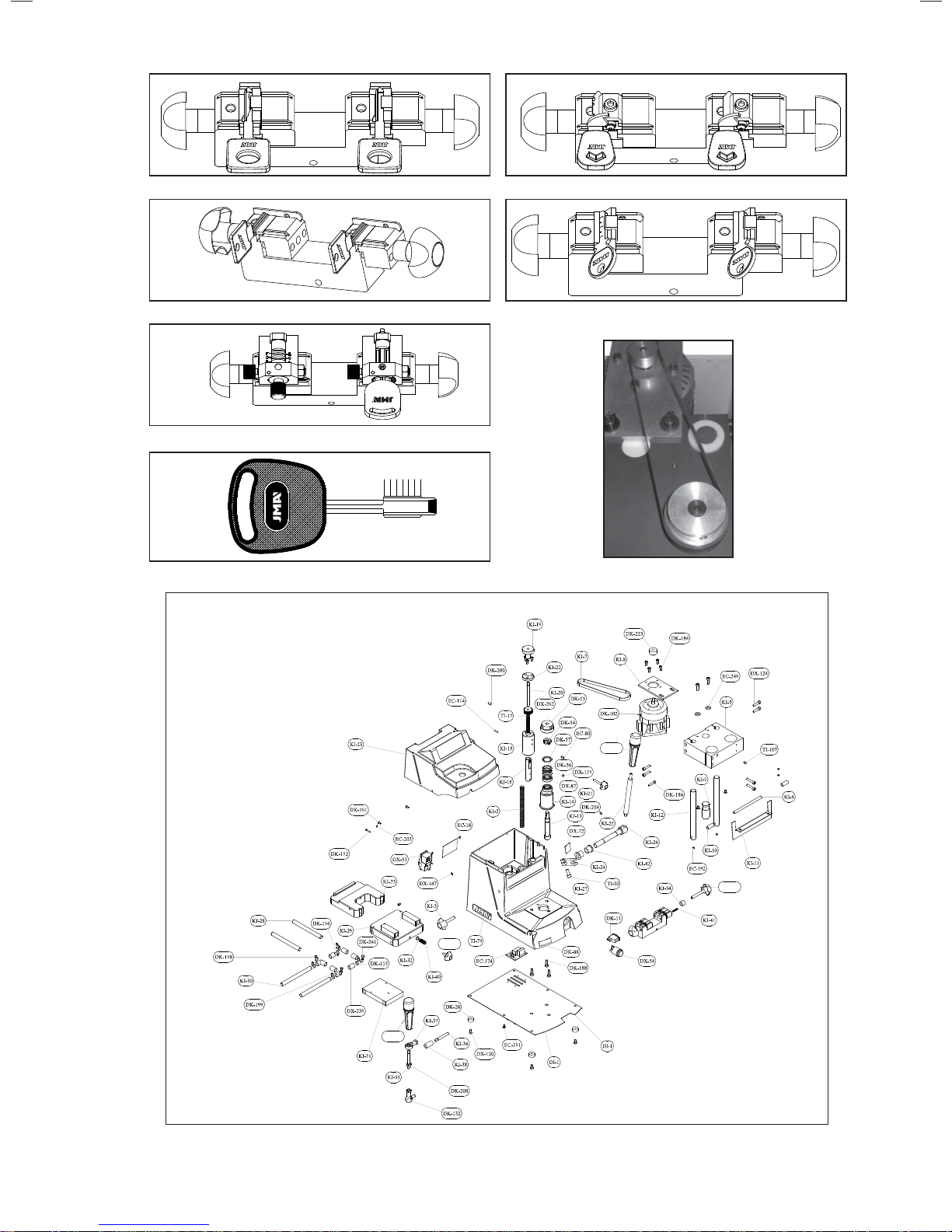
See figure 9
See figure 10
Lower the tracer point very slightly by turning the
•
corresponding adjustment wheel (around 1/10 of a
turn).
• Insert the tracer point in the groove in the key
blade and lock the machine head.
• Raise the tracer point slightly so that it does not
drag the key.
• It is recommendable to make a preliminary rough-
grinding run and then another finishing run,
following the whole marking profile of the key.
Machine it downwards (from the tip to the head of
the key).
3.2.3 ME-3.P and ME-4.P type keys
• Milling cutter and tracer point F-11 / P-11 are used
for cutting these keys.
• To clamp the keys in the clamps, adaptor AD-MM2
will need to be used (see diagram).
- Place the adaptors on the clamp.
- Insert the two keys in their respective adaptors.
- Fit the adaptor to the clamp until it reaches its limit.
The key will then be clamped in its adaptor.
• Adjust the heights of the milling cutter and tracer
point, and take the tracer point out of flexible
mode.
• Lower the tracer point very slightly by turning the
corresponding adjustment wheel (around 1/10 of a
turn).
• Insert the tracer point in the groove in the key
blade and lock the machine head.
• Raise the tracer point slightly so that it does not
drag the key.
• Make the first key-cutting run.
• As these keys are reversible, only turn the key to be
cut, making the second run on this key.
3.2.4 JIS-4.P keys
• Milling cutter and tracer point F-11 / P-11 are used
for cutting these keys.
• To clamp the keys in the clamps, adaptor AD-MJ
will need to be used (see diagram).
- Position the adaptors and fix them to the clamp.
- Insert the two keys in their respective adaptors
(until they reach their limit on the turning plate,
against the key stops). In this position, clamp the
keys to their adaptors.
• Adjust the heights of the milling cutter and tracer
point, and take the tracer point out of flexible
mode.
• Make the first cutting run.
• Turn the two keys on the other side of the adaptor,
and proceed as described in the above process for
placing the keys.
• Make the second run.
See figure 11
See figure 12
3.2.5 WIN-1D, WIN-2D, WIN-3D and WIN-4D keys
• Milling cutter and tracer point F-15 / P-15 are used
for cutting these keys.
• Clamp two flat key blanks in the clamp, and use
them to adjust the heights of the milling cutter and
tracer point.
• Take the tracer point out of flexible mode, and
take out the two flat key blanks.
• To clamp the keys in the clamps, the “Winhaus
template P-WIN” adaptor will be needed (see
diagram).
- Position the adaptors on the clamp.
See figure 13
English
1111
Page 6

4
Maintenance
and safety
- Place the key in the correct position with the grooves facing upwards (as shown in the diagram).
- Clamp the keys in the clamps with the aid of the
adaptor, making a tip stop.
• Precisely insert the tracer point in one of the points,
and lock the machine head at this height.
• Cut the key.
3.2.6 KABA keys
• The milling cutters and tracer points to be used will
English
depend on the model of Kaba key you wish to cut.
To find out which model of milling cutter and tracer point needs to be used, consult the list in point
5 of this manual.
• To clamp the keys in the clamps, adaptor AD-5º,
AD-15º or AD-45º will need to be used, depending
on which Kaba key you wish to cut (see diagram).
- Position the adaptors on the clamp.
- Mount the keys in their corresponding adaptors,
with the key head pointing towards the key cutting machine (as shown in the diagram).
- Clamp the adaptor in the clamp, making a tip
stop against the adaptor. The key will be clamped
in its adaptor.
• Obtain the code from the first of the two rows of
holes on this face of the key blade.
• Turn the key so that the head points towards the
machine. In this position, obtain the code from the
second row of holes.
• Carry out the same procedures for the other key
face.
3.2.7 FO-6.P type keys
• Milling cutter and tracer point F-22 / P-22 are used
for cutting these keys.
• The corresponding adaptor will need to be used to
obtain the code for this key.
- Position the adaptors and clamp them to the
clamp.
- When placing the key, ensure it is perfectly flat so
that the two cutting runs are exactly the same.
• Adjust the heights of the milling cutter and tracer
point, and take the tracer point out of flexible
mode.
• Insert the tracer point into the channel for one of
the letters. Lock the head height and slightly raise
the tracer point so that it does not hit the adaptor.
• Cut the key.
Reading the original key code:
• The original key has 6 duplicating positions, defi-
ned by letters A, B, C, D, E and F, as shown in the
figure below.
In each of the key positions 4 different combinations are
possible (defined by numbers). These are as follows:
1 2 3 4
See figure 14
See figure 15
See figure 16
The following points must be complied with when
carrying out any maintenance operations:
Never carry out any operations with the machine
1
running.
2
Unplug the cable from the mains.
3
Strictly follow the indications given in the manual.
Use original spares only.
4
Replacing the belt
4.1
The procedure for checking the belt is correctly tightened,
or for replacing it, is as follows:
1
Switch off the machine at the master switch and
unplug the connection cable.
2
Remove the four screws holding the machine guard
in place.
Loosen the two screws holding the motor support to
3
the head.
Tighten or replace the belt.
4
To tighten the belt, push the motor towards the rear
5
of the machine and tighten the two screws holding the
motor support to the head.
6
To replace the belt, carry out the same procedure as for
tightening it, but with a new belt.
Replacing the fuses
4.2
If the machine does not start up when the start-up switches are activated, you should check the fuses.
This is done as follows:
Switch off the machine at the master switch and
1
unplug the connection cable.
2
Remove the fuse holder beside the master switch.
Using a tester, check for any blown fuses, and if this
3
is the case, replace them with new fuses of the same
type and power.
Safety recommendations
4.3
1
Do not attempt to start up or handle the machine before having read, understood and complied with all the
safety recommendations, installation instructions, user
guide and maintenance procedures.
Always unplug the machine from the mains before
2
carrying out any cleaning or maintenance.
Always keep the machine and its surrounding area
3
clean.
See figure 17
• Height” 1 indicates that the key should not be cut.
Position 2 indicates there is a slight recess in the key,
and position 3 that there is a slightly larger recess. The
largest recess in the key is indicated by height 4.
• Take the key and mark the combinations of each of
the 6 positions, as shown in the example below:
POSITION A B C D E F
COMBINATION 3 4 1 2 4 2
NOTE: The series of numbers in the combination is the key code.
12
Page 7

REFERENCIA MARCA FRESA PALPADOR INCLINACION ADAPTADOR
REFERENCE No. BRAND M.CUTTER T.POINT ANGLE ADAPTER
ARTIKELNUMMER
CODICE MARCA FRESA TASTATORE INCLINAZIONE ADATTATORE
REFERENCE MARQUE FRAISE PALPEUR ANGLE ADAPTATEUR
REFERÊNCIA MARCA FRESA PALPADOR INCLINAÇÃO ADAPTADOR
ABC-6 ABC F-5 T-5
ABC-7 ABC F-5 T-5
ABL-1 ABLOY F-11 T-11 AD-ABL
ABL-2 ABLOY F-11 T-11 AD-ABL
ABL-3 ABLOY F-11 T-11 AD-ABL
ABL-4 ABLOY F-11 T-11 AD-ABL
ABU-16 ABUS F-1 T-1
ABU-34 ABUS F-1 T-1 AD-CI
ABU-61 ABUS F-1 T-1 AD-CI
ABU-63 ABUS F-1 T-1 AD-CI
AGA-12 AGA F-13 T-13
AGA-25 AGA F-13 T-13
AGA-29 AGA F-5 T-5
AGA-38 AGA F-5 T-5
AGA-39 AGA F-5 T-5
AGA-42 AGA F-5 T-5
AGA-43 AGA F-5 T-5
AGA-44 AGA F-5 T-5
AGB-2 AGB F-1 T-1
AMG-8D AMIG F-5 T-5
AMG-9D AMIG F-5 T-5
AMG-10 AMIG F-5 T-5
AMG-10D AMIG F-5 T-5
AP-1D APEX F-13 T-13
AX-2.P AXA F-1 T-1
AZ-7 AZBE F-15 T-15
AZ-8D AZBE F-5 T-5
AZ-9 AZBE F-13 T-13
AZ-12 AZBE F-13 T-13
AZ-14 AZBE F-13 T-13
AZ-29 AZBE F-13 T-13
BAG-1 BAGEM F-1 T-1
BEY-1D BEY F-13 T-13
BKY-1 BORKEY F-1 T-1
BKY-2 BORKEY F-1 T-1
BM-1.P BMW F-1 T-1
BM-4 BMW F-11 T-11 AD-MJ
BM-5.P BMW F-11 T-11 AD-MJ
BRAS-1 BRAS F-13 T-13
BUL-1 BULAT F-1 T-1
BRI-16 BRICARD F-1 T-1
BRI-25 BRICARD F-1 T-1
BRI-26 BRICARD F-1 T-1
BRI-27 BRICARD F-1 T-1 AD-CI
BRI-28 BRICARD F-1 T-1 AD-CI
BRI-29 BRICARD F-1 T-1 AD-CI
BRI-30 BRICARD F-1 T-1 AD-CI
CAY-2 CAYS F-1 T-1
CHU-10 CHUBB F-1 T-1
CI-14 CISA F-1 T-1
CI-17 CISA F-1 T-1
CI-21 CISA F-1 T-1 AD-CI
CI-25 CISA F-1 T-1 AD-CI
CI-26 CISA F-1 T-1 AD-CI
CI-30 CISA F-1 T-1 AD-CI
CI-31 CISA F-1 T-1 AD-CI
CI-32 CISA F-1 T-1 AD-CI
CI-33 CISA F-1 T-1 AD-CI
CI-35 CISA F-1 T-1 AD-CI
CI-48 CISA F-1 T-1 AD-CI
COR-37 IFAM F-19 T-19
CVL-9D CVL F-13 T-13
DAF-2 DAF F-13 T-13
DAF-3D DAF F-13 T-13
DAF-4D DAF F-13 T-13
DEK-3 DEKABA F-1 T-1
DEK-8 DEKABA F-1 T-1
DLC-1 DELCA F-1 T-1
DLC-2 DELCA F-1 T-1
DO-3 DOMUS F-1 T-1
DO-4 DOMUS F-1 T-1
HERSTELLER FRÄSER TASTER NEIGUNG ADAPTER
30
Page 8

REFERENCIA MARCA FRESA PALPADOR INCLINACION ADAPTADOR
REFERENCE No. BRAND M.CUTTER T.POINT ANGLE ADAPTER
ARTIKELNUMMER
CODICE MARCA FRESA TASTATORE INCLINAZIONE ADATTATORE
REFERENCE MARQUE FRAISE PALPEUR ANGLE ADAPTATEUR
REFERÊNCIA MARCA FRESA PALPADOR INCLINAÇÃO ADAPTADOR
DOM-17I DOM F-1 T-1
DOM-22 DOM F-1 T-1
DOM-30 DOM F-1 T-1
DOM-31 DOM F-1 T-1
DOM-32 DOM F-1 T-1
DOM-33 DOM F-1 T-1 AD-STS
DOM-34 DOM F-1 T-1 AD-STS
DOM-39 DOM F-1 T-1
DOM-43 DOM F-1 T-1
DOM-B1 DOM F-1 T-1
ELZ-10 ELZETT F-1 T-1
EZ-DS10 EZCURRA F-1, F-16 T-1, T-16
EZ-DS10E EZCURRA F-1, F-16 T-1, T-16
EZ-DS15 EZCURRA F-1, F-16 T-1, T-16
EZ-DS15R EZCURRA F-1, F-16 T-1, T-16
FAV-2 BYP F-5 T-5
FAC-19 FAC F-1 T-1
FAY-1D FAYN F-5 T-5
FI-16P TRW-SIPEA F-11 T-11
FO-6.P FORD F-22 T-22 AD-FO
FO-24P FORD F-11 T-11 AD-FO24
FTH-7 FTH F-5 T-5
FTH-16 FTH F-5 T-5
FTH-23 FTH F-5 T-5
FTH-24 FTH F-5 T-5
FTH-25 FTH F-5 T-5
FTH-26D FTH F-5 T-5
FTH-29 FTH F-5 T-5
GDA-1.P GERDA F-1 T-1
GIOB-3.P LANCIA F-6 T-6
HOND-17.P HONDA F-11 T-11
HU-2.P HUF F-11 T-11
HU-DH.P VOLVO F-11 T-11
HU-DN.P VOLVO F-11 T-11
HU-HAA.P1 HUF F-11 T-11 AD-AUDI
IF-2 IFAM F-1 T-1
IF-4 IFAM F-1 T-1
IF-6 IFAM F-19 T-19
IR-1.P IR F-1 T-1
IS-6D ISEO F-13 T-13
IS-10.P ISEO F-1 T-1
IS-14D ISEO F-1 T-1
ITO-2D ITO F-1 T-1
JIS-4.P JIS F-11 T-11 AD-MJ
KA-1 KABA (8) F-1 T-1
KA-2 KABA (20) F-5, F43 T-5, T-43 45º AD-45º
KA-3 KABA (GEMINI) F-1 T-1 15º AD-15º
KA-4 KABA (CUATRO) F-1 T-1 15º AD-15º
KA-4 KABA NUEVA F-1 T-26 45º ADAPTADOR KA-4
KA-5 KABA F-5 T-5
KA-6 KABA F-1 T-1
KA-7 KABA F-1 T-1
KA-8 KABA F-1 T-1
KA-10 KABA F-1 T-1
KA-11 KABA F-1 T-1
KAE-1 KALE F-1 T-1
KAE-2 KALE F-1 T-1
KAE-4 KALE F-1 T-1
KAE-10D KALE F-1 T-1
KE-1 KESO F-1 T-1 5º AD-5º
KE-2 KESO F-1 T-1
KE-3 KESO (2000) F-5 T-5
KE-4 KESO (2000) F-1 T-1
JAU-1.P TIBBE F-1 T-1
JAU-2.P TIBBE F-1 T-1
LAP- 4 LAPERCHE F-13 T-13
LAP- 8D LAPERCHE F-13 T-13
LAP-10D LAPERCHE F-13 T-13
LAP-11D LAPERCHE F-13 T-13
LAP-13.P LAPERCHE F-13 T-13
LAP-17.P LAPERCHE F-13 T-13
HERSTELLER FRÄSER TASTER NEIGUNG ADAPTER
31
Page 9

REFERENCIA MARCA FRESA PALPADOR INCLINACION ADAPTADOR
REFERENCE No. BRAND M.CUTTER T.POINT ANGLE ADAPTER
ARTIKELNUMMER
CODICE MARCA FRESA TASTATORE INCLINAZIONE ADATTATORE
REFERENCE MARQUE FRAISE PALPEUR ANGLE ADAPTATEUR
REFERÊNCIA MARCA FRESA PALPADOR INCLINAÇÃO ADAPTADOR
LAP-20.P LAPERCHE F-13 T-13
LAP-21.P LAPERCHE F-13 T-13
LAP-22.P LAPERCHE F-13 T-13
LAP-23.P LAPERCHE F-13 T-13
LIN-13 LINCE F-12B T-12B
LIN-13 LINCE F-5 T-5
LIN-19D LINCE F-5 T-5
LIN-21D LINCE F-1 T-1
MAS-15P MASTER F-6 T-6
MASL-1 MASTER LOCK F-1 T-1
MAZ-12.P1 MAZDA F-1 T-1
MCM- 4SS MCM F-1 T-1
MCM- 4SS MCM F-B T-B
MCM- 4SS MCM F-C T-C
MCM-10 MCM F-13 T-13
MCM-16 MCM F-1 T-1
ME-2.P MERCEDES F-11 T-11 AD-MJ
ME-3.P MERCEDES F-11 T-11 AD-MJ
ME-4.P MERCEDES F-11 T-11 AD-MM
ME-5.P MERCEDES F-11 T-11 AD-MM
ME-6.P MERCEDES F-11 T-11 AD-MM
ME-7.P MERCEDES F-11 T-11 AD-MM
ME-8.P MERCEDES F-11 T-11 AD-MM
ME-10.P MERCEDES F-11 T-11 AD-MM
ME-11.P MERCEDES F-11 T-11 AD-MM
ME-12.P MERCEDES F-11 T-11 AD-MM
MLM-4 MLM F-1 T-1
MULT-2.P MULTLOCK F-12A T-12A
MULT-2.P MULTLOCK F-12B T-12B
MULT-3.P MULTLOCK F-12A T-12A
MULT-3.P MULTLOCK F-12B T-12B
MULT-4.P MULTLOCK F-12A T-12A
MULT-4.P MULTLOCK F-12B T-12B
MULT-5.P MULTLOCK F-12A T-12A
MULT-5.P MULTLOCK F-12B T-12B
MUL-T10.P MULTLOCK F-12A T-12A
MUL-T10.P MULTLOCK F-12B T-12B
NE-40.P VOLVO F-11 T-11
NE-41.P VOLVO F-11 T-11
NE-51P2 PEUGEOT F-11 T-11
OJ-Q OJMAR F-5 T-5
OMC-3 OMEC F-1 T-1
OMC-4 OMEC F-1 T-1
OP-11C1 OPEL F-11 T-11
OP-WH.P OPEL F-11 T-11
OP-WHC OPEL F-11 T-11
OP-WY.P OPEL F-11 T-11
PEN-2 PENZMASH F-1 T-1
PEU-1C1 PEUGEOT/ VALEO F-11 T-11
PEU2C1 VALEO/PEUGEOT F-11 T-11
PIC-8D PICARD F-1 T-1
ROSE-1 ROSSETTI F-1 T-1
SAA-1.P SAAB F-11 T-11
SEA-1 SEA F-3 T-3 Canal
SEA-1 SEA F-1 T-1 Lateral
SEA-2 SEA F-3 T-3 Canal
SEA-2 SEA F-1 T-1 Lateral
SCR-1 SECURITAL F-1 T-1
SIP-4P4 TRW-SIPEA F-11 T-11
SIP4-P3 TRW-SIPEA F-11 T-11
SPI-1 SPIDER F-1 T-1
SPI-1D SPIDER F-1 T-1
STS-35 STS F-1 T-1
STS-36 STS F-1 T-1
STS-37 STS F-1 T-1
STS-38 STS F-1 T-1
T-10P STS-TESA F5 T-5
T-10 STS – TESA F-13 T-13
T-10 2005 TESA F-1 T-1
TE-T11 TESA F-5 T-5
T-14 STS F-5 T-5
HERSTELLER FRÄSER TASTER NEIGUNG ADAPTER
3232
Page 10

REFERENCIA MARCA FRESA PALPADOR INCLINACION ADAPTADOR
REFERENCE No. BRAND M.CUTTER T.POINT ANGLE ADAPTER
ARTIKELNUMMER
CODICE MARCA FRESA TASTATORE INCLINAZIONE ADATTATORE
REFERENCE MARQUE FRAISE PALPEUR ANGLE ADAPTATEUR
REFERÊNCIA MARCA FRESA PALPADOR INCLINAÇÃO ADAPTADOR
TE-T60 TESA F-5 T-5
TE-T61 TESA F-5 T-5
TE-T80 TESA F-5 T-5
TE-T80SC TESA F-5 T-5
TEC-2 TECSESA F-5 T-5
TIT-6 TITAN F-1 T-1
TOV-2 TOVER F-1 T-1
TOV-4 TOVER F-1 T-1
TOV-5 (2f25) TOVER F-1 T-1
TOV-5 (2f25) TOVER F-6 T-6
TOV-6 TOVER F-1 T-1
TOV-7 TOVER F-1 T-1
TOYO-18.P TOYOTA F-11 T-11
TV-3 IX - STS -TESA F-1 T-1
TV-5 IX - STS -TESA F-1 T-1
TV-8 IX - STS -TESA F-1 T-1
TV-9 IX – STS - TESA F-1 T-1
UCEM-5D UCEM F-14 T-14
UCEM-5I UCEM F-14 T-14
UCEM-8D.P UCEM F-13 T-13
UCEM-13D UCEM F-13 T-13
UCEM-17D UCEM F-13 T-13
VA-15 VACHETTE F-21 T-21
VA-70 VACHETTE F-1 T-1
CIT-1.P VALEO F-11 T-11
PEU-1.P VALEO F-11 T-11
VI-14 VIRO F-13 T-13
WIN-1D WINKHAUS F-15 T-15 P-WIN
WIN-1I WINKHAUS F-15 T-15 P-WIN
WIN-2D WINKHAUS F-15 T-15 P-WIN
WIN-3D WINKHAUS F-15 T-15 P-WIN
WIN-4D WINKHAUS F-15 T-15 P-WIN
X-5 STS - TESA F-5 T-5 AD-STS
X-6 STS - TESA F-5 T-5 AD-STS
YA-23 YALE F-11 T-11 AD-JIS
YAR-1 YARDENI F-1 T-1
YAR-2 YARDENI F-1 T-1
ZA-10 ZADI F-1 T-1
HERSTELLER FRÄSER TASTER NEIGUNG ADAPTER
3333
Page 11
Tipo:
N de Serie:
O
-
ALEJANDRO ALTUNA, S.A.
Bidekurtzeta, 6
20500 MONDRAGON
(Guipuzcoa) Spain
12
8
7
Figura 1 / Figure 1 / Abbildung 1
1
0
Fuses
1
1
2
3
Figura 3 / Figure 3 / Abbildung 3
14
10
9
6
2
11
13
3
4
15
3
4
17
2
M
5
Figura 2 / Figure 2 / Abbildung 2
1
165
Figura 2 / Figure 2 / Abbildung 2
Figura 4 / Figure 4 / Abbildung 4 Figura 5 / Figure 5 / Abbildung 5 Figura 6 / Figure 6 / Abbildung 6
Figura 7 / Figure 7 / Abbildung 7 Figura 8 / Figure 8 / Abbildung 8
Figura 9 / Figure 9 / Abbildung 9 Figura 10 / Figure 10 / Abbildung 10
34
Page 12
DAKKI
IX-2006
DX-26
DX-26
KI-4
KI-43
Figura 11 / Figure 11 / Abbildung 11 Figura 12 / Figure 12 / Abbildung 12
Figura 13 / Figure 13 / Abbildung 13 Figura 14 / Figure 14 / Abbildung 14
Figura 15 / Figure 15 / Abbildung 15
ABCDEF
Figura 16 / Figure 16 / Abbildung 16 Figura 17 / Figure 17 / Abbildung 17
Page 13

Bidekurtzeta, 6. Apdo. 70
20500 Arrasate-Mondragón
(Gipuzkoa) ESPAÑA
Tel. + 34 943 79 30 00 / 943 79 33 32
Fax. + 34 943 79 72 43
www.jma.es
e-mail:[email protected]
 Loading...