

Page 1

sBOX8D / sBOX8R
GPI Control Panel for eBOX & gBOX
User Manual
Page 2

sBOX8D, sBOX8R, gBOX eBOX are trademarks of JLCooper Electronics. All
other brand names are the property of their respective owners.
sBOX8D/sBOX8R User Manual, Second Edition
Part Number 932131
©2014 JLCooper Electronics, 142 Arena Street, El Segundo, CA 90245 USA
phone (310) 322-9990 fax (310) 335-0110 web www.jlcooper.com
2
Page 3

Table of Contents
...............................................................................Introduction 4
........................................................................sBOX Variations 5
................................................................................Installation 6
.............................................................................................eBOX 6
.............................................................................................gBOX 7
...........................................................................Multiple sBOXes 8
..............................................................................Rack Mounting 9
..........................................................................Configuration 10
..........................................................................................eBOX 11
..........................................................................................gBOX 13
..............................................................................Button Action 15
.................................................................................Operation 16
............................................................Using the GPI Outputs 17
......................................................................Troubleshooting 19
......................................................................Care and Service 19
......................................................Declaration of Conformity 20
.............................................RoHS Statement of Compliance 21
................................JLCooper Electronics Limited Warranty 20
3
Page 4

Introduction
The sBOX8D and sBOX8R are companion products to the JLCooper eBOX and
gBOX GPI Interfaces.
The sBOX8D and sBOX8R connect to the eBOX and gBOX using an
included expansion cable and provides a convenient user interface to
trigger GPI outputs of an eBOX or gBOX.
Each sBOX can manage a bank of 8 GPI outputs at a time. For
flexibility, an sBOX can be configured to be able to bank switch among
groups of 8 GPI outputs. Or, an sBOX can be configured to address a set
bank of 8 GPI outputs.
Multiple sBOXes can be chained together to form larger user interfaces
or to allow for multiple control areas.
The expansion cable that connects the sBOX to either the eBOX or
gBOX carries the data signals and power to the sBOX. No separate
power supply is required for the sBOX.
4
Page 5

sBOX Variations
sBOX8D - Desktop Version
Note: The labels shown in the buttons are for illustrative purposes and are
not included with the unit.
sBOX8R - Rackmount Version
Note: The labels shown in the buttons are for illustrative purposes and are not
included with the unit.
The sBOX is available in two form factors, the sBOX8D which is the
desktop version and the sBOX8R which is the rackmount version. The
two different versions are shown below.
The functionality and configuration of the two versions is identical. This
allows a system to be comprised of sBOX8Ds and sBOX8Rs.
5
Page 6
Installation
1 2 3
GPI Output
eBOX
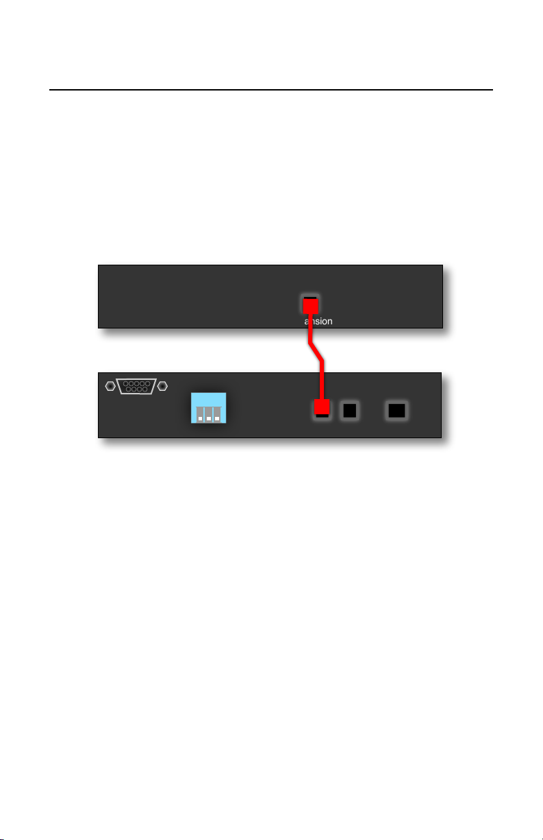
Installation of the sBOX with an eBOX is straightforward. Simply
connect the sBOX to the eBOX using the supplied cable as shown in the
image below.
Expansion
eBOX
Bank
Expansion
Aux
sBOX8
Connecting an eBOX to an sBOX8
6
Page 7

gBOX
GPI Output
Installation of the sBOX with the gBOX is just as straightforward.
Simply connect the sBOX to the gBOX using the supplied cable as
shown in the image below.
Expansion
gBOX
1 2 3
Bank
Expansion
Connecting an gBOX to an sBOX8
Aux
sBOX8
7
Page 8
Multiple sBOXes
GPI Output
GPI Output
GPI Output
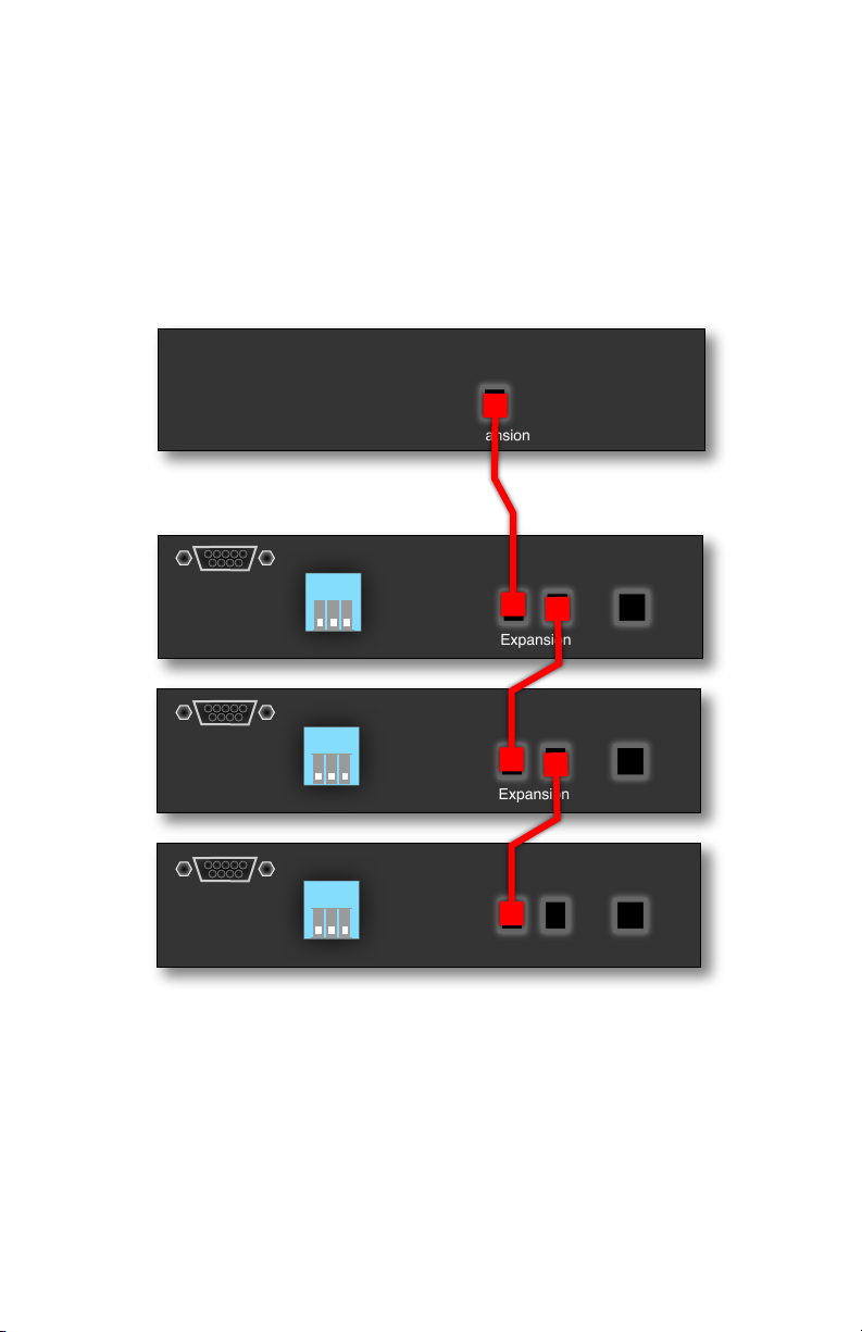
Installation of multiple sBOXes with an eBOX or gBOX is similarly
straightforward. Simply connect the sBOXes to the eBOX or gBOX in a
“daisy chain” fashion using the supplied cables as shown in the image
below.
Expansion
eBOX
1 2 3
Bank
Expansion
Aux
sBOX8 #1
1 2 3
Bank
Expansion
Aux
sBOX8 #2
1 2 3
Bank
Expansion
Aux
sBOX8 #3
Connecting an eBOX to multiple sBOX8s
8
Page 9

Rack Mounting
Mounting an eBOX and sBOX8R to the JLC-Racktray
The sBOX8R is designed to be mounted in a standard 19 inch rack. This
can be accomplished by using the optional JLCooper Racktray. The part
number for this item is JLC-RACKTRAY.
Mounting the sBOX8R to the racktray is straightforward. Simply follow
the directions below.
1. Remove any rubber feet from the bottom of the unit.
2. Align the mounting holes on the bottom of the unit with two
mounting holes on the racktray.
3. Screw the included 6-32 screws into the holes.
4. Turn the screws clockwise until the unit is securely mounted to
the racktray.
5. Repeat for any additional unit such as an eBOX or another
sBOX8R.
6. Install racktray into rack with four rack screws (not included).
9
Page 10
Configuration
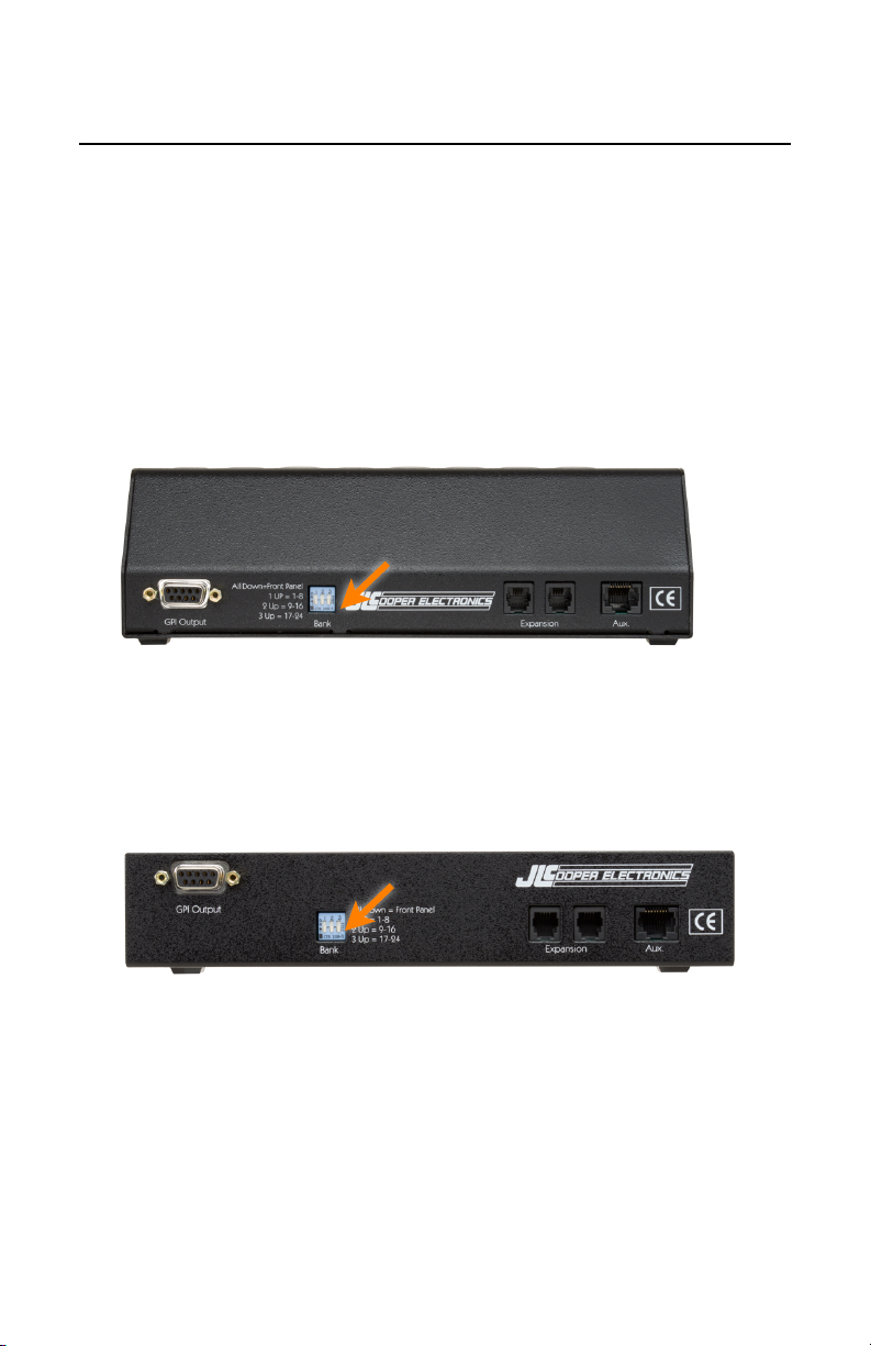
sBOX8D - Rear Panel
sBOX8R - Rear Panel
Configuration of the sBOX is performed by the rear panel DIP switches.
By default, the sBOX GPI Outputs can be selected by the Bank button on
the left side of the front panel. Using the rear panel DIP switches, the
sBOX can be configured to control a specific bank of 8 GPI Outputs.
The following pictures below identify the location of the rear panel DIP
switches.
10
Page 11

eBOX
sBOX
Button
Bank
1-8
Bank
9-16
Bank
17-24
119172210183311194412205513216614227715238816
24
sBOX Button to eBOX GPI Mapping
The eBOX has 24 GPI Outputs. Using the sBOX, they are accessed in
three banks of eight GPI Outputs. The following table shows the
mapping of the sBOX buttons to the actual GPI Outputs in the various
banks.
11
Page 12
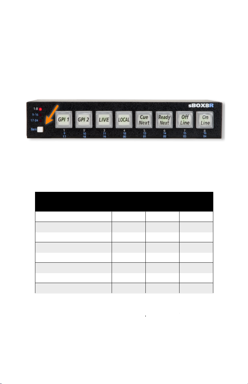
The Bank Button on the front panel of the sBOX can determine the
Location of Bank Button on sBOX8R
Note: The labels shown in the buttons are for illustrative purposes and are
not included with the unit.
sBOX
Mode
DIP
SW1
DIP
SW2
DIP
SW3
Bank 1-8, 9-16, 17-24*
Down
Down
Down
Bank 1-8
Up
Down
Down
Bank 9-16
Down
Up
Down
Bank 17-24
UpUpDown
Not used
Down
DownUpNot used
Up
DownUpNot used
DownUpUp
Not used
UpUpUp
sBOX Operational Mode Configuration for eBOX
* This mode allows the Bank button to select the bank of GPIs to
control.
control.
behavior of the large buttons on the sBOX. The sBOX allows switching
between three banks of 8 GPI and Outputs using the Bank Button
highlighted in the picture below.
Using the rear panel DIP switches, the sBOX can be configured to
control a specific bank of 8 GPI Outputs. In this setting, the Bank Button
has no effect.
12
Page 13

gBOX
sBOX
Button
Bank
1-8
Bank
9-16
Bank
17-24
Bank
25-32
Bank
33-40
Bank
41-48
119172533412210182634423311192735434412202836445513212937456614223038467715233139478816243240
48
sBOX Button to gBOX GPI Mapping
sBOX Button to gBOX GPI Mapping
The gBOX has 48 GPI Outputs. Using the sBOX, they are accessed in
six banks of eight GPI Outputs. The following table shows the mapping
of the sBOX buttons to the actual GPI Outputs in the various banks.
13
Page 14

The Bank Button on the front panel of the sBOX can determine the
Location of Bank Button on sBOX8R
Note: The labels shown in the buttons are for illustrative purposes and are
not included with the unit.
sBOX
Mode
DIP
SW1
DIP
SW2
DIP
SW3
Bank 1-8, 9-16, 17-24*
Down
Down
Down
Bank 1-8
Up
Down
Down
Bank 9-16
Down
Up
Down
Bank 17-24
UpUpDown
Bank 25-32, 33-40, 41-48*
Down
DownUpBank 25-32
Up
DownUpBank 33-40
DownUpUp
Bank 41-48
UpUpUp
sBOX Operational Mode Configuration for gBOX
* This mode allows the Bank button to select the bank of GPIs to
control.
behavior of the large buttons on the sBOX.
By default, the sBOX GPI Outputs can be selected by the Bank button on
the left side of the front panel. Using the rear panel DIP switches, the
sBOX can be configured to control a specific bank of 8 GPI Outputs.
Using the rear panel DIP switches, the sBOX can be configured to
control/view a specific bank of 8 GPI Outputs. In this setting, the Bank
Button has no effect.
14
Page 15

Button Action
LED
Behavior
Button
Behavior
Steady
To gg l e
Flashing
Momentary
sBOX Button to eBOX GPI Mapping
The behavior of the GPI Buttons can be configured to act as a
momentary switch or toggle switch. To change the behavior of the GPI
Buttons, simply press and hold the Bank Button for 3 seconds. The GPI
Buttons will indicate their behavior by the state of the LEDs.
To change the Button behavior press and hold the Bank Button for 3
seconds. Continue holding the Bank button and press the GPI Button
until the desired behavior is indicated by the LED state. After the
buttons have been configured, release the Bank button.
15
Page 16

Operation
Using the sBOX is straightforward.
1. If Bank switching is enabled, simply press the Bank Button until the
desired bank of GPI Outputs is selected and,
2. Press the desired GPI Button to change the state of the GPI Output.
16
Page 17

Using the GPI Outputs
sBOX Function
GPI Output
Pin
Ground
1
sBOX GPI 1
3
sBOX GPI 2
2
sBOX GPI 3
4
sBOX GPI 4
8
sBOX GPI 5
9
sBOX GPI 6
7
sBOX GPI 7
6
sBOX GPI 8
5
sBOX GPI Output Pinout
Switch LED
State
GPI Output
State
On
0 Volts
Off
5 Volts
sBOX GPI Output State
The sBOX has a 9 pin D-Subminiature connector that has 8 GPI outputs.
These outputs mirror the state of switch LEDs 1-8 on the front panel.
The outputs are CMOS outputs.
17
Page 18

The outputs of the sBOX GPI ports are CMOS. The output signal
1
74HC374
GPI Output Example #1 with LED
2
5 Volts
!
1
74HC374
GPI Output Example #2 with LED
2
is referenced to pin 1 of the GPI Output Port. The GPI Outputs
deliver 0 or +5 volts and are rated to +/- 6mA.
74HC374
Detail of GPI Output
Note: Because the outputs are CMOS, the output voltage MUST be limited to
voltage levels between 0 and 5 volts. This can occur if driving a circuit that is
powered by a voltage higher than 5 volts.
The example circuits below shows a GPI Output driving an LED.
This also applies to driving the LED of an optoisolator input.
18
Page 19

Troubleshooting
If for some reason the sBOX8 does not give you the expected results,
take a moment to do some investigating. The most important concept is
that you have your sBOX8 connected properly as outlined in Installation
and Use. Take a moment to double check your setup.
What is the state of the DIP switches?
In addition, the JLCooper website (www.jlcooper.com) will contain up to
date information on drivers, applications and troubleshooting.
If all else fails, you can contact the JLCooper Service Department at:
service@jlcooper.com.
Care and Service
If properly cared for, your sBOX8 should provide years of trouble free
performance. While the sBOX8 is built in a rugged metal enclosure,
please avoid dropping the sBOX8.
Clean with a soft, damp cloth. Do not allow liquids, dust or other foreign
matter to get inside the unit.
There are no user-serviceable parts in the sBOX8. Please refer to the
JLCooper Electronics Limited Factory Warranty on the last page for
detailed warranty and service information.
19
Page 20

JLCooper Electronics Limited Warranty
JLCooper Electronics ("JLCooper") warrants this product to be free of defects in materials or
workmanship for a period of 12 months from the date of purchase. This warranty is nontransferable and the benefits apply only to the original owner. Proof of purchase in the form of
an itemized sales receipt is required for warranty coverage. To receive service under this
warranty, customers in the United States should contact the JLCooper factory at (310)
322-9990 and talk to a service technician. If necessary, a Return Authorization number may be
issued. For our customers outside the United States, it is recommended that you first contact
your Dealer or Distributor, since they may offer their own service or support policy. If local
support is not obtainable, please send a FAX to JLCooper's Service Department at +1 310 335
0110 with a detailed description of the service required. Upon issuance of return authorization,
the product should be packed in the original shipping materials and shipped prepaid and
insured to: Service Department, JLCooper Electronics, 142 Arena Street, El Segundo, CA
90245. Please include the following: copy of the sales receipt, your name and address (no P.O.
Boxes, please), a brief description of the problem, and any other related items discussed with
the service department and considered necessary to evaluate the product or effect a repair. The
return authorization number must be clearly written on the outside of the package. JLCooper
will at its option, without charge for parts or labor, either repair or replace the defective
part(s) or unit. Carriage, insurance, customs duties, impounds, tariffs, taxes, surcharges,
brokerage fees and other shipping costs are not covered by this warranty. JLCooper's normal
repair turn around time at the factory is approximately 15 business days from receipt of
product to shipping. Your actual turn around time will include return shipping. Actual turn
around time will vary depending upon many factors including the repeatability of the
customer's reported complaint, the availability of parts required for repair, the availability of
related products needed to evaluate the product if necessary. Priority services are available at
additional cost. These should be discussed with the service technician at the time the return
authorization is issued. This warranty provides only the benefits specified and does not cover
defects or repairs needed as result of acts beyond the control of JLCooper including but not
limited to: abuse, failure to operate in accordance with the procedures outlined in this owner's
manual; nor does it cover damage from accident, negligence, using incorrect power supply,
modification, alteration, improper use, unauthorized servicing, tampering, ingress of foreign
matter; nor for damage from natural or man-made events such as, but not limited to flooding,
lightning, electrostatic discharge, tornadoes, earthquake, fire, civil unrest, war, terrorism, etc.
THE DURATION OF ANY OTHER WARRANTIES, WHETHER IMPLIED OR EXPRESS,
INCLUDING BUT NOT LIMITED TO THE IMPLIED WARRANTY OF MERCHANTABILITY,
IS LIMITED TO THE DURATION OF THE EXPRESS WARRANTY HEREIN. JLCOOPER
HEREBY EXCLUDES INCIDENTAL AND CONSEQUENTIAL DAMAGES, INCLUDING
BUT NOT LIMITED TO: LOSS OF TIME, INCONVENIENCE, DELAY IN PERFORMANCE
OF THIS WARRANTY, THE LOSS OF USE OF THE PRODUCT OR COMMERCIAL LOSS,
AND FOR BREACH OF ANY EXPRESS OR IMPLIED WARRANTY OF MERCHANTABILITY APPLICABLE TO THIS PRODUCT. JLCOOPER SHALL NOT BE LIABLE FOR
DAMAGES OR LOSS RESULTING FROM THE NEGLIGENT OR INTENTIONAL ACTS OF
THE SHIPPER OR HIS CONTRACT AFFILIATES. THE CUSTOMER SHOULD CONTACT
THE SHIPPER FOR PROPER CLAIMS PROCEDURES IN THE EVENT OF DAMAGE OR
LOSS RESULTING FROM SHIPMENT. THIS WARRANTY SHALL BE GOVERNED BY THE
LAWS OF THE STATE OF CALIFORNIA.
20
 Loading...