

Page 1
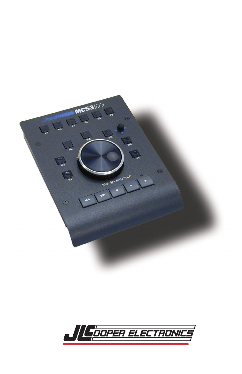
Media Control Station
9 Pin Version
3
User's Manual First Edition
©1999-2002 JLCooper Electronics
142 Arena Street • El Segundo, CA 90245 U.S.A
Page 2

MCS, Media Control Station, MCS3, and Media Control Station3 are trademarks of
JLCooper Electronics. All other brand names are the property of their respective
holders.
MCS3 9 Pin User's Manual First Edition
Part Number for this manual is 932076-9pin
©1999 -2002 JLCooper Electronics • 142 Arena Street • El Segundo,
U.S.A.
(310)322-9990
(310)322-0110 fax
www.jlcooper.com
CA 90245
Page 3

Table of Contents
Introduction................................................. 4
3
Connecting the MCS
Features and Operation .............................. 6
Transports ..................................................... 6
V-Stick ........................................................... 6
Jog Mode....................................................... 7
Shuttle Mode................................................. 7
Shuttle LEDs.................................................. 7
Locate............................................................ 8
Track Arming Analog or Digital Machines... 9
Track Number Shifting ................................. 9
Track Mapping.............................................10
Technical Information .............................. 11
3
MCS
Specifications ...............................................11
Care and Service ..........................................11
Warranty.......................................................12
as Computer Controller .....................11
..........................................
5
3
Page 4

Introduction
The JLCooper Media Control Station3 is a remote control for
VTRs and other machines that support Sony 9 Pin "P2"
protocol.
The MCS3 controls professional analogue and digital VTRs,
modular digital multitracks, and disk-based VTR emulators.
The MCS3 can also operate in certain applications as a control
station “input device” for computer-based editing systems.
The MCS3 features a smooth, weighted and optically encoded
jog shuttle wheel with concentric shuttle ring, and transport
and function keys.
As shipped from the factory, the MCS3 is normally configured
and “ready to use” as a VTR controller.
When the MCS3 is intended to be used as an input device for a
computer editing system, it will need to be reconfigured
internally. Instructions for doing this are provided at the end of
this manual.
This manual relates to the features and operation of the MCS
as a 9 Pin/2 controller. If the MCS3 is used as an input device to
a computer-based system, follow the instructions included with
the system.
Please take a moment to send in your product registration card,
so we can notify you in the future about any new products or
updates as they become available.
3
4
Page 5

3
Connecting the MCS
Connect the supplied external power supply to the power jack
on the MCS3's captive cable.
In case a replacement supply is used, see to it that it has the
same rating as the original supply: The power supply's output
is rated at 9 volts DC, 500 mA, with a center positive 2.1 mm
plug.
Connect MCS3 9 Pin cable to the 9 Pin remote input of the
machine that you are controlling.
5
Page 6

Features and Operation
Transport Functions
The Transports control Rewind, Fast Forward, Stop, Play, and
Record. Pause is enabled by pressing the button marked W7.
The Record button is interlocked with the Play button.
To enable Record, you must hold down one and push the
other.
Record only operates if tracks have been enabled (“armed”)
first. (See Track Enabling below.)
To Record, first arm tracks. Then press and release Play, and
allow the machine to come up to speed.
Then press Play again and hold it down.
While holding down Play, press Record.
Then release both switches.
While in Record mode, the pressing of the Play button send a
Record Exit command, dropping the controlled unit out the
record state.
V-Stick Functions
The “V/Stick” is located to the upper right of the jog/shuttle
control. It is a soft, four position switch.
The switch is activated by applying pressure either left, right,
toward you, or away from you. (It is not necessary to press
down or rotate the control.) It performs the following
• V-Stick Down = Reverse 2x Speed
• V-Stick Up = Forward 2x Speed
• V-Stick Left = Reverse 1x Speed
• V-Stick Right = Forward 1x Speed
functions
:
6
Page 7

Jog Mode
The center wheel is for Jog mode. In Jog mode, playback
speed and direction is proportional to the speed and direction
that the wheel is rotated.
Rotate the wheel clockwise for forward playback.
Rotate the wheel counter clockwise for reverse playback.
In Jog mode, continuously rotating the wheel results in 1X play
speed, either forward or backward.
To stop the tape, simply stop turning the wheel.
Shuttle Mode
The outer ring is for Shuttle mode. In Shuttle mode, playback
speed is related to the extent of rotation away from the starting
position of the wheel.
Rotate the ring clockwise for forward shuttle.
Rotate the ring counter clockwise for reverse shuttle.
The program continues to shuttle until the ring is returned to
its center position. Alternately, simply press Stop.
Shuttle LEDs
Normally, on power up, the shuttle ring LEDs will not light
until the shuttle ring is centered.
After that, the shuttle ring LEDs will light depending upon the
direction of rotation from center. Both LEDs are on when the
ring is centered.
7
Page 8

Locate Functions
The MCS3 may be “taught” locations either on the fly (program
is playing) or while stationary (program is stopped.)
Locates are stored by pressing and holding the Record button,
and while holding the Record button, press W1 thru W6.
A location request will be sent, and the response stored within
the MCS3 . This will be remembered until power is removed
from the MCS3 .
The MCS3 stores six locate points:
• W1 Locate 1
• W2 Locate 2
• W3 Locate 3
• W4 Locate 4
• W5 Locate 5
• W6 Locate 6
8
Page 9

Track Arming Analog or Digital Machines
The MCS3 can send the appropriate commands for track
arming analog or digital machines.
The unit normally is configured for digital track arming.
To change modes, press and hold down buttons F5 and F6 at
the same time.
While holding down F5 and F6, press F2 to change to analog
mode.
While holding down F5 and F6, press F1 to return to digital
mode.
Track Number Shifting
Function Keys F1 - F4 can be used to arm tracks 1 - 4, and
Function Keys F1 - F4 can be used to arm tracks 5 - 8.
Function Keys F5 & F6 act as track number "shift buttons".
For example,
F1 through F4 toggle the track arming state of tracks 1 - 4.
Press and release F6:
F1 through F4 now toggle the track arming state of tracks 5 - 8.
Press and release F5:
F1 through F4 now toggle the track arming state of tracks 1 - 4
again.
Be aware that the MCS3 has no knowledge of any track
enabling done on the front panel of the VTR machine itself.
Nor does it know the status of the machine when the MCS3 is
first powered on. The MCS3 powers-up operating under the
assumption that all tracks are not enabled.
9
Page 10

Analog Machine Track Mapping
Actual mapping of tracks to audio/video is machine
dependent, and should be confirmed before doing any real
editing.
Typically, the mapping is:
Track 1- Audio Track 1
Track 2- Audio Track 2
Track 3- Time Code
Track 4- not used
Track 5- Video
Track 6- Assemble
Track 7- Insert
Track 8- not used
10
Page 11

Technical Information
MCS3 as Computer Controller
The RS-422/P2 MCS3 can operate in either of two modes,
either as a stand-alone Master Controller for machines that
respond to the so-called “P2” format, or as a “Slave RS-422
device” meant to be attached to a Master Host. This generally
means that the MCS3 is a control station for a computer-based
editing system.
As shipped from the factory, the MCS3 is normally configured
as a Master device, but is easily re-configured for “Slave/Host”
mode to act as a computer input device. To do so, a 5/64"
Allen wrench and a small flat-blade screwdriver are needed.
(1) Remove the four screws from the front.
(2) Carefully slide the cable’s strain relief from its slot on the
unit bottom.
(3) On the small circuit board, remove the 8-pin IC which is
inserted into U3 “To Mach.” and move it over to the “To Host”
socket. Make sure orientation is preserved.
(4) Remove the jumper JB1. Store the jumper by placing it over
only one pin of JB1.
(5) Carefully re-insert the strain relief, dress the inside section
of cable away from the sensitive Jog Wheel assembly, and reinsert the four screws.
Specifications
Dimensions:...................6.5" X 7" X 1.25"
Shipping Weight ............ 3.7 lbs.
Care and Service
If properly cared for, your MCS3 should provide years of
trouble-free performance. Avoid dropping the MCS3, or hard
banging on the keys.
Clean with a soft cloth dampened with window cleaner.
Do not allow liquids to get inside the unit.
There are no user-serviceable parts in the MCS3. Please refer to
the really fine print following for detailed warranty and service
information.
11
Page 12

JLCooper Electronics Limited Factory Warranty
JLCooper Electronics (“JLCooper”) warrants this product to be free of defects in
materials or workmanship for a period of 12 months from the date of purchase.
This warranty is non-transferable and the benefits apply to the original owner. Proof
of purchase in the form of an itemized sales receipt is required for
To receive service under this warranty, customers in the United States should
contact the JLCooper factory at (310) 322-9990 and talk to a service technician.
If necessary, a Return Authorization number may be issued.
For our customers outside the United States, it is recommended that you first contact
your Dealer or Distributor, since they may offer their own service or support policy.
If local support is not obtainable, please send a FAX to JLCooper’s
at (310) 335-0110, with a detailed description of the service required.
Upon issuance of return authorization, the product should be properly packed and
shipped to Service Department, JLCooper Electronics, 142 Arena St., El Segundo, CA
90245.
Please include the following: copy of the sales receipt, your name and address (no
P.O. Boxes, please), a brief description of the problem, and any other related items
discussed with the service department and considered necessary to evaluate the
product or effect a repair. The return authorization number must be clearly written
on the outside of the package.
JLCooper will, without charge for parts or labor, either repair or replace the
defective part(s). Shipping costs are not covered by this warranty.
JLCooper’s normal repair turn around time at the factory is approximately 15
business days, from receipt of product to shipping. Your actual turn around time will
include return shipping.
Actual turn around time will vary depending upon many factors including the
repeatability of the customer’s reported complaint, the availability of parts required
for repair, the availability of related products needed to evaluate the product if
necessary.
Priority services are available. These should be discussed with the service technician
at the time the return authorization is issued.
This warranty provides only the benefits specified and does not cover defects or
repairs needed as result of acts beyond the control of JLCooper including but not
limited to: abuse, damage by accident/negligence, modification, alteration, improper
use, unauthorized servicing, tampering, or failure to operate in accordance with the
procedures outlined in the owner’s manual; nor for acts of God such as flooding,
lightning, tornadoes, etc.
THE DURATION OF ANY OTHER WARRANTIES, WHETHER IMPLIED OR EXPRESS,
INCLUDING BUT NOT LIMITED TO THE IMPLIED WARRANTY OF
MERCHANTABILITY, IS LIMITED TO THE DURATION OF THE EXPRESS
WARRANTY HEREIN. JLCOOPER HEREBY EXCLUDES INCIDENTAL AND
CONSEQUENTIAL DAMAGES, INCLUDING BUT NOT LIMITED TO: LOSS OF TIME,
INCONVENIENCE, DELAY IN PERFORMANCE OF THIS WARRANTY, THE LOSS OF
USE OF THE PRODUCT OR COMMERCIAL LOSS, AND FOR BREACH OF ANY
EXPRESS OR IMPLIED WARRANTY OF MERCHANTABILITY, APPLICABLE TO THIS
PRODUCT. JLCOOPER SHALL NOT BE LIABLE FOR DAMAGES OR LOSS
RESULTING FROM THE NEGLIGENT OR INTENTIONAL ACTS OF THE SHIPPER
OR HIS CONTRACT AFFILIATES. THE CUSTOMER SHOULD CONTACT THE
SHIPPER FOR PROPER CLAIMS PROCEDURES IN THE EVENT OF DAMAGE OR
LOSS RESULTING FROM SHIPMENT.
warranty coverage.
Service Department
 Loading...