

Page 1
gBOX
Ethernet to GPI Interface
Users Manual
Page 2

2
gBOX, eBOX and eBOX I/O are trademarks of JLCooper Electronics. All other
brand names are the property of their respective owners.
gBOX User’s Manual, First Edition
Part Number 932126
©2011 JLCooper Electronics, 142 Arena Street, El Segundo, CA 90245 USA
(310) 322-9990 (310) 335-0110 www.jlcooper.com
Page 3

3
Table of Contents
Introduction ................................................................................... 4!
Setup ............................................................................................... 5!
Unpacking ................................................................................... 5!
Connections ................................................................................. 5!
Configuration ................................................................................ 7!
Operating Modes ........................................................................ 7!
Ethernet ................................................................................... 7!
Serial ....................................................................................... 7!
Expander ................................................................................. 7!
Ethernet Interface ....................................................................... 8!
Mode Selection ....................................................................... 8!
Server Mode ............................................................................ 9!
Client Mode .......................................................................... 10!
Serial Interface .......................................................................... 11!
Expander ................................................................................... 11!
gBOX Security ........................................................................... 12!
Technical Reference .................................................................... 13!
Electrical Connections .............................................................. 13!
Ethernet ................................................................................. 13!
Serial ..................................................................................... 14!
GPI Port Pinouts ................................................................... 16!
GPI Port Circuitry Details ..................................................... 17!
Power ............................................................................................ 19!
Troubleshooting .......................................................................... 20!
Care and Service ....................................................................... 21!
Declaration of Conformity ......................................................... 22!
RoHS Statement of Compliance ................................................ 23!
JLCooper Electronics Limited Warranty ................................ 24!
Page 4

4
Introduction
The gBOX is a general purpose interface box that converts up to
48 GPI (General Purpose Interface) inputs and outputs to
100/10baseT Ethernet or a serial interface. Up to 8 gBOXes may
be slaved off a master gBOX to convert up to a total of 432 GPI
inputs and outputs.
The gBOX communicates over standard TCP/IP which allows it be
used with any host computer running any operating system that
uses TCP/IP protocol. The gBOX can also be connected to other
gBOXes to allow longer runs than traditional GPI cables. Since
the gBOX uses TCP/IP, traffic can be routed over internal LANs,
wireless LANs, MANs, WANs and even over the public Internet.
Unit configuration is accomplished using the rear panel DIP
switches.
When the gBOX is outfitted with an Ethernet Interface (JLCooper
p/n 920394) the unit functions as either a server or client. When
configured as a server, it passively waits for client devices to
connect to it. The device can be a computer or another gBOX
configured as a client. When the gBOX is configured as a client, it
will actively attempt to connect to the server gBOX. Once this is
accomplished, the either gBOX will pass data received in the serial
or GPI ports to the remote gBOX. If there is no data received in
the gBOX, the gBOX will not send any TCP packets.
Page 5

5
Setup
Unpacking
The gBOX package will contain the following items:
• gBOX
• Power Supply
• This Users Manual
• Four rubber feet
Connections
The gBOX connections are straightforward:
1. Plug the power supply into the gBOX.
2. Install an Ethernet or serial interface into the interface slot.
3. Connect Ethernet cable or serial cable to unit.
4. Connect GPI cables into GPI ports.
Page 6

6
Pin
Function
Pin
Function
1
Ground
1
Ground
2
GPI 1
2
GPI 25
3
GPI 2
3
GPI 26
4
GPI 3
4
GPI 27
5
GPI 4
5
GPI 28
6
GPI 5
6
GPI 29
7
GPI 6
7
GPI 30
8
GPI 7
8
GPI 31
9
GPI 8
9
GPI 32
10
GPI 9
10
GPI 33
11
GPI 10
11
GPI 34
12
GPI 11
12
GPI 35
13
GPI 12
13
GPI 36
14
GPI 13
14
GPI 37
15
GPI 14
15
GPI 38
16
GPI 15
16
GPI 39
17
GPI 16
17
GPI 40
18
GPI 17
18
GPI 41
19
GPI 18
19
GPI 42
20
GPI 19
20
GPI 43
21
GPI 20
21
GPI 44
22
GPI 21
22
GPI 45
23
GPI 22
23
GPI 46
24
GPI 23
24
GPI 47
25
GPI 24
25
GPI 48
gBOX Master GPI In/Out Pinout
Page 7

7
Configuration
Operating Modes
Ethernet
When the gBOX has an Ethernet Interface installed, it has two
distinct modes of operation that are set by the rear panel DIP
switches. The modes are:
• Server
• Client
The DIP switches are read only at power on so the gBOX must be
power cycled for the changes to take effect.
Serial
When the gBOX has a serial Interface installed, it has just one
distinct mode of operation. This is GPI to serial conversion.
Expander
When the gBOX has an Ethernet or serial interface installed, it is a
master unit, which communicates directly with another master unit
or a host computer.
When the gBOX does not have an interface installed, it becomes
an Expander gBOX. An Expander gBOX adds 48 additional GPI
Inputs and Outputs to a Master gBOX. An Expander gBOX
connects to a Master gBOX using an Expander cable plugged into
one of the Expander ports on the rear panel. Up to 8 Expander
gBOXes can be added to a master gBOX.
Page 8
8
Ethernet Interface
When MCS-Ethernet Interface is installed, the rear panel DIP
switches on the left side set the IP Address and behavior of the
gBOX.
The rear panel DIP switches on the right side are currently not used
and are ignored.
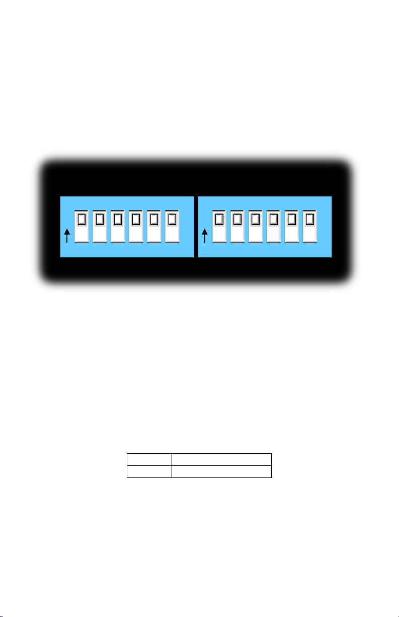
Mode Selection
When DIP switch 5 on the left side is in the Off position, the
gBOX behaves as a server. That is, the gBOX waits for a device
such as a host computer or client gBOX to establish a connection
to it. Conversely, when DIP switch 5 is in the On position, the
gBOX behaves as a client. That is, the gBOX attempts to connect
to a server device such as a server gBOX to establish a connection
to it.
SW5
Mode
Off
Server
On
Client
Mode Selection of gBOX
Figure 1
CONFIGURATION
1 2 3 4 5 6 O N 1 2 3 4 5 6 O
N
Page 9

9
Server Mode
In the Server Mode of operation, DIP Switches 1, 2, 3 and 4 on the
left side set the IP address of the gBOX. The units IP address is set
according to the table below.
SW1
SW2
SW3
SW4
Off
Off
Off
Off
192.168.254.102
On
Off
Off
Off
192.168.254.104
Off
On
Off
Off
192.168.254.106
On
On
Off
Off
192.168.254.108
Off
Off
On
Off
192.168.254.110
On
Off
On
Off
192.168.254.112
Off
On
On
Off
192.168.254.114
On
On
On
Off
192.168.254.116
Off
Off
Off
On
10.0.0.128
On
Off
Off
On
10.0.0.130
Off
On
Off
On
10.0.0.132
On
On
Off
On
172.16.0.128
Off
Off
On
On
172.16.0.130
On
Off
On
On
Not used
Off
On
On
On
Not used
On
On
On
On
User Setting
Left DIP Switch Settings
Note: The gBOX listens on TCP port 23.
Page 10

10
Client Mode
In the Client Mode of operation, DIP Switches 1, 2, 3 and 4 on the
left side set the IP address of the gBOX. The units IP address is set
according to the table below.
SW1
SW2
SW3
SW4
Off
Off
Off
Off
192.168.254.103
On
Off
Off
Off
192.168.254.105
Off
On
Off
Off
192.168.254.107
On
On
Off
Off
192.168.254.109
Off
Off
On
Off
192.168.254.111
On
Off
On
Off
192.168.254.113
Off
On
On
Off
192.168.254.115
On
On
On
Off
192.168.254.117
Off
Off
Off
On
10.0.0.129
On
Off
Off
On
10.0.0.131
Off
On
Off
On
10.0.0.133
On
On
Off
On
172.16.0.129
Off
Off
On
On
172.16.0.131
On
Off
On
On
Not used
Off
On
On
On
Not used
On
On
On
On
User Setting
Left DIP Switch Settings
Note: The gBOX attempts to connect to TCP port 23 on the server.
Page 11

11
Serial Interface
When the 920465 Standard RS-422 Interface Card or 920466
Standard RS-232 Interface Card is installed, the rear panel DIP
switches on the left side set the serial port parity. The bitrate of the
gBOX is fixed at 38400 bits/sec.
SW1
SW2
On x No Parity
Off
Off
Odd Parity
Off
On
Even Parity
x = Don’t Care
Serial Port Parity Settings
Expander
The gBOX can be daisy chained to allow one Ethernet or Serial
connection to accommodate up to 432 GPI Inputs and Outputs.
When the rear panel slot is vacant, the gBOX assumes it is an
expander unit and uses the rear panel DIP switches 1, 2 and 3 on
the left side to set the expander ID. The expander ID as defined in
the table below.
SW1
SW2
SW3
Off
Off
Off
Expander #1 (GPI 49-96)
On
Off
Off
Expander #2 (GPI 97-144)
Off
On
Off
Expander #3 (GPI 145-192)
On
On
Off
Expander #4 (GPI 193-240)
Off
Off
On
Expander #5 (GPI 241-288)
On
Off
On
Expander #6 (GPI 289-336)
Off
On
On
Expander #7 (GPI 337-384)
On
On
On
Expander #8 (GPI 385-432)
gBOX Expander Unit Definition
Page 12

12
gBOX Security
The gBOX contains a basic security mechanism that prevents
unintended hosts or gBOXes from passing data through a secured
gBOX. A gBOX can be protected with password that is set on the
configuration web page. The password is stored in nonvolatile
memory and, is read upon power up.
When password protection is enabled, the sending gBOX embeds
the password in the transmitted IP packet. At the remote end, the
receiving gBOX must have password protection enabled AND
have a matching password.
The DIP switches are read only at power on so the gBOX must be
power cycled for any changes to take effect.
This security mechanism is only used in gBOX Server and gBOX
Client modes. SW6 should be set to the off position when used in
the GPI to Serial and GPI to Ethernet modes.
SW6 On
Disable password protection
Off
Enable password protection
Security Configuration
The effect of SW6 takes place immediately.
Note: If a gBOX has password protection is disabled; it will ignore the
password and act on any packets sent to it.
Page 13

13
Technical Reference
Electrical Connections
Ethernet
This gBOX port is just like Ethernet ports on a computer, to
connect it to a hub, switch or router, use a straight through cable.
To connect it to another gBOX or computer, use a crossover cable.
The gBOX supports IEEE 802.3u clause 28 Auto-Negotiation that
automatically senses the Ethernet port speed & duplex operation
and chooses the highest performance settings.
In addition, four LEDs on the front panel that indicate various
operating conditions of the Ethernet port. These LEDs are:
• Link
• 100BaseT activity
• 10BaseT activity
• Collision
Page 14

14
Serial
When the 920466 Standard RS-232 Interface Card or the 920465
Standard RS-422 Interface Card is installed the unit is a simple
GPI to serial converter. The pinout of the serial interface is
detailed in the table below.
Interface
RS-232C
RS-422A
RS-422A
“Mach”
“Host”
Pin 1
not used
not used
not used
Pin 2
Transmit
Receive A
Transmit A
Pin 3
Receive
Transmit B
Receive B
Pin 4
not used
Ground
Ground
Pin 5
Ground
not used
not used
Pin 6
not used
Ground
Ground
Pin 7
not used
Receive B
Transmit B
Pin 8
not used
Transmit A
Receive A
Pin 9
not used
not used
not used
Serial Port Pinout
Page 15

15
Serial port communications occurs with the following parameters:
• Bit rate: 38400 bits/sec
• Start bits: 1
• Data bits: 8
• Stop bits: 1
The parity of the serial port can be set on the leftmost set of DIP
switches on the rear panel. The parity is set using the following
table.
Switch 1
Switch 2
Parity
Down
Down
Odd
Down
Up
Even
Up
x
None
Serial Port Parity Selection
X= Don’t Care
Page 16

16
GPI Port Pinouts
The GPI ports on the rear of the gBOX are 25 pin D-sub
connectors. The GPI In connector has 24 TTL/CMOS compatible
inputs with internal pull-ups to +5 volts. The GPI Out connector
has 24 TTL/CMOS compatible outputs. On both connectors, pin 1
is the ground reference and pins 2-25 are the GPI signals.
When gBOXes connected together in a client/server manner
establish a connection, both client and server gBOXes will send
the state of its GPI In ports to each other so it can be shown on the
GPI Out port on the remote gBOX. After that, changes to a GPI In
port will cause a gBOX to send a GPI message to the remote
gBOX. Additionally, the gBOXes will send a GPI message every
5 seconds to keep the connection alive and to refresh the state of
the GPI outputs.
A packet is sent whenever a change to the GPI In is sensed. At
present, it is sampled about every 20 milliseconds. This can be
changed via the configuration web page.
MSB
LSB
Byte1
Pin 9
Pin 8
Pin 7
Pin 6
Pin 5
Pin 4
Pin 3
Pin 2
Byte2
Pin 17
Pin 16
Pin 15
Pin 14
Pin 13
Pin 12
Pin 11
Pin 10
Byte3
Pin 25
Pin 24
Pin 23
Pin 22
Pin 21
Pin 20
Pin 19
Pin 18
gBOX GPI 1-24 In/Out Pinouts
MSB
LSB
Byte4
Pin 9
Pin 8
Pin 7
Pin 6
Pin 5
Pin 4
Pin 3
Pin 2
Byte5
Pin 17
Pin 16
Pin 15
Pin 14
Pin 13
Pin 12
Pin 11
Pin 10
Byte6
Pin 25
Pin 24
Pin 23
Pin 22
Pin 21
Pin 20
Pin 19
Pin 18
gBOX GPI 25-48 In/Out Pinouts
Pin 1 is ground.
Page 17
17
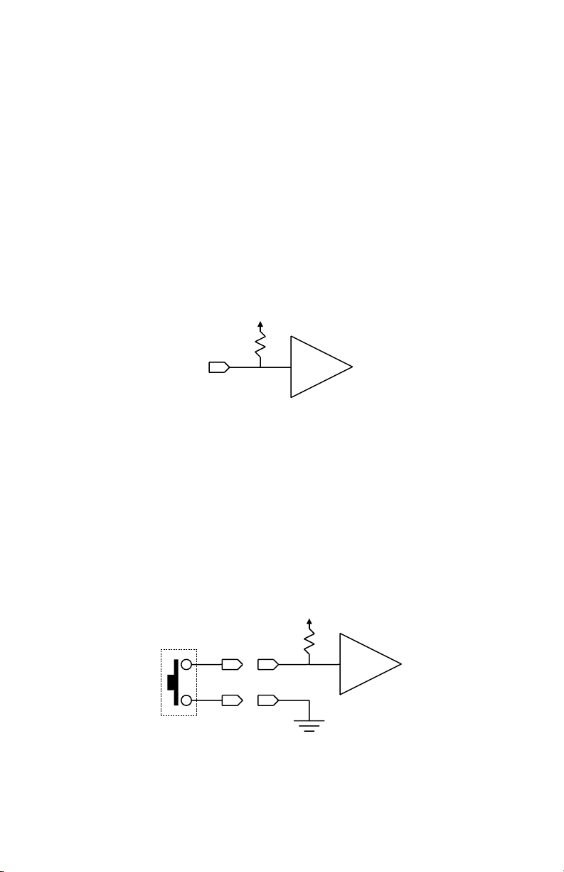
GPI Port Circuitry Details
The gBOX GPI input and output circuits are detailed in the
following section.
The inputs of the gBOX GPI ports are CMOS inputs. The input
circuitry has a 4700 ohm pullup resistor to +5 volts as referenced
to pin 1 of the GPI Input Port.
Note: Because the inputs are CMOS, the input voltage MUST be
limited to voltage levels between 0 and 5 volts. If this is not possible,
consider using the gBOX I/O.
The internal pullup resistor insures that the input pin is set to a
known state. The default state of the GPI Inputs is +5 volts or a
logic state of ‘1’ in the GPI message bitmap. The internal pullup
resistor also allows a simple switch or ‘dry contact’ to be
connected between a GPI Input pin and ground as shown in the
example below.
74HC244
5 Volts
Detail of GPI Input
4700Ω
4700Ω
74HC244
5 Volts
GPI Input Example with Pushbutton Switch
1
2
Page 18

18
The outputs of the gBOX GPI ports are also CMOS. The output
signal is referenced to pin 1 of the GPI Output Port. The GPI
Outputs are rated to +/- 6mA. If this is not sufficient for your
application, consider using the eBOX I/O.
Note: Because the inputs are CMOS, the output voltage MUST be
limited to voltage levels between 0 and 5 volts. This can occur if
driving a circuit that is powered by a voltage higher than 5 volts. If
this is not possible, consider using the gBOX I/O.
The example circuits below shows a GPI Output driving an LED.
74HC374
Detail of GPI Output
1
74HC374
GPI Output Example #1 with LED
2
5 Volts
1
74HC374
GPI Output Example #2 with LED
2
Page 19

19
Power
The gBOX requires a 9 volt DC, center positive power supply
capable of delivering at least 500 milliamps. The unit comes with
a power supply appropriate for the country in which the unit was
sold. If you need a power supply specific to your location, please
contact your local distributor or JLCooper Electronics.
Location
JLCooper Part Number
North America
561026-4
Europe
561026-4
Approved Power Supplies
Warning: Using a power supply other than the units specified in the
above table can result in damage to the gBOX and/or other equipment,
which is not covered by the JLCooper Factory Warranty.
Page 20

20
Troubleshooting
If for some reason the gBOX does not give you the expected
results, take a moment to do some investigating. The most
important concept is that you have your gBOX connected properly
as outlined in Installation and Use. Take a moment to double
check your setup.
• What is the state of the DIP switches?
• Do the 10 red LEDs flash alternately at power up?
• Do the Link and 100 (or 10) LEDs light up?
• In any mode, can you ping it
(ping 192.168.254.102)?
• If you are using the password protection feature, is it
enabled in both gBOXes?
• In webpage configuration mode, can you communicate
with it using the web page?
• In normal client or server mode, can you communicate with
it using the gBOX Configuration Utility?
• The ARP Cache in the host application may have the
incorrect entry for the gBOX's IP address. Try clearing the
ARP cache (arp -d in Windows).
• In normal server mode, if you telnet to the gBOX, do you
see a short packet of unprintable characters every 5 seconds
as shown in the screenshot below?
Page 21

21
If you are using the gBOX Configuration Utility, be sure to reboot
the gBOX for the settings to take effect
A common problem is forgetting to turn the power switch on or
turning the unit on after the software application has launched.
In addition, the JLCooper website (www.jlcooper.com) will
contain up to date information on drivers, applications and
troubleshooting.
If all else fails, you can contact the JLCooper Service Department
at: service@jlcooper.com.
Care and Service
If properly cared for, your gBOX should provide years of trouble
free performance. While the gBOX is built in a rugged metal
enclosure, please avoid dropping the gBOX.
Clean with a soft, damp cloth. Do not allow liquids, dust or other
foreign matter to get inside the unit.
There are no user-serviceable parts in the gBOX. Please refer to
the JLCooper Electronics Limited Factory Warranty on the last
page for detailed warranty and service information.
Page 22

22
Declaration of Conformity
JLCooper Electronics declares that the product named below conforms to:
Low Voltage Directive (LVD) 2006/95/EC
(Superceded LVD73/23/EEC) on 16th January 2006.
Low Voltage Directive (LVD) 73/23/EEC
(Directive 73/23/EC has recently been the subject of a codification,
requiring a new number)
gBOX
Warning: The installer is responsible for protection against personal contact
with all live connections to power supplies, which contain hazardous voltages.
Company Address:
142 Arena Street
El Segundo, CA, 90245 U.S.A.
Product Name: gBOX Interface
Product Type: Network Interface
Model Number: gBOX
Date of Issue: 16 September 2009
Authorized by:
Title of Authority: Quality Assurance
Declaration Reference: CE/EEC2007TLL
Page 23

23
RoHS Statement of Compliance
June 28, 2006
Re: gBOX
This is a declaration that the items described (herein as RoHS “Class 1”) do not
contain one or more than one:
RoHS restricted substances above the homogeneous material concentration limit
(Threshold Level) per the EU/RoHS directive effective July 1, 2006 and
amending document(s).
JLCooper Electronics products will meet MIL-I 45208. The Company is
currently implementing procedures for ISO 9000:2000, after which feasibility
research will begin for ISO 14000 considerations.
RoHS Class 1 OEM Products:
Hazardous Substance Allowed PPM Level
Cadmium (Cd) 100ppm (0.01%)
Lead (Pb) 1000ppm (0.1%)
Mercury (Hg) 1000ppm (0.1%)
Hexavalent Chromium (CrVI) 1000ppm (0.1%)
Polybrominated Biphenyl's (PBB's) 1000ppm (0.1%)
Polybrominated Diphenyl Ethers (PBDE's) 1000ppm (0.1%)
Supplier evidence of compliance on file meets or exceeds trace ability
requirements of ISO 9000:2000. Where feasible, JL Cooper seeks suppliers with
ISO 9000:2000 Quality and ISO 14000 Environmental Certification.
Sincerely,
Thomas L. Lowry
Quality Assurance Department
Page 24

24
JLCooper Electronics Limited Warranty
JLCooper Electronics ("JLCooper") warrants this product to be free of defects in materials or
workmanship for a period of 12 months from the date of purchase. This warranty is non-
transferable and the benefits apply only to the original owner. Proof of purchase in the form of
an itemized sales receipt is required for warranty coverage. To receive service under this
warranty, customers in the United States should contact the JLCooper factory at (310) 322-
9990 and talk to a service technician. If necessary, a Return Authorization number may be
issued. For our customers outside the United States, it is recommended that you first contact
your Dealer or Distributor, since they may offer their own service or support policy. If local
support is not obtainable, please send a FAX to JLCooper's Service Department at +1 310 335
0110 with a detailed description of the service required. Upon issuance of return authorization,
the product should be packed in the original shipping materials and shipped prepaid and
insured to: Service Department, JLCooper Electronics, 142 Arena Street, El Segundo, CA
90245. Please include the following: copy of the sales receipt, your name and address (no P.O.
Boxes, please), a brief description of the problem, and any other related items discussed with
the service department and considered necessary to evaluate the product or effect a repair. The
return authorization number must be clearly written on the outside of the package. JLCooper
will at its option, without charge for parts or labor, either repair or replace the defective part(s)
or unit. Carriage, insurance, customs duties, impounds, tariffs, taxes, surcharges, brokerage
fees and other shipping costs are not covered by this warranty. JLCooper's normal repair turn
around time at the factory is approximately 15 business days from receipt of product to
shipping. Your actual turn around time will include return shipping. Actual turn around time
will vary depending upon many factors including the repeatability of the customer's reported
complaint, the availability of parts required for repair, the availability of related products
needed to evaluate the product if necessary. Priority services are available at additional cost.
These should be discussed with the service technician at the time the return authorization is
issued. This warranty provides only the benefits specified and does not cover defects or repairs
needed as result of acts beyond the control of JLCooper including but not limited to: abuse,
failure to operate in accordance with the procedures outlined in this owner's manual; nor does
it cover damage from accident, negligence, using incorrect power supply, modification,
alteration, improper use, unauthorized servicing, tampering, ingress of foreign matter; nor for
damage from natural or man-made events such as, but not limited to flooding, lightning,
electrostatic discharge, tornadoes, earthquake, fire, civil unrest, war, terrorism, etc.
THE DURATION OF ANY OTHER WARRANTIES, WHETHER IMPLIED OR EXPRESS,
INCLUDING BUT NOT LIMITED TO THE IMPLIED WARRANTY OF
MERCHANTABILITY, IS LIMITED TO THE DURATION OF THE EXPRESS
WA RR A N TY H ER E I N. J L CO O P ER H E RE B Y E X C LU D ES I N CI D E NT AL AN D
CONSEQUENTIAL DAMAGES, INCLUDING BUT NOT LIMITED TO: LOSS OF TIME,
INCONVENIENCE, DELAY IN PERFORMANCE OF THIS WARRANTY, THE LOSS OF
USE OF THE PRODUCT OR COMMERCIAL LOSS, AND FOR BREACH OF ANY
EXPRESS OR IMPLIED WARRANTY OF MERCHANT-
ABILITY APPLICABLE TO THIS PRODUCT. JLCOOPER SHALL NOT BE LIABLE FOR
DAMAGES OR LOSS RESULTING FROM THE NEGLIGENT OR INTENTIONAL ACTS
OF THE SHIPPER OR HIS CONTRACT AFFILIATES. THE CUSTOMER SHOULD
CONTACT THE SHIPPER FOR PROPER CLAIMS PROCEDURES IN THE EVENT OF
DAMAGE OR LOSS RESULTING FROM SHIPMENT. THIS WARRANTY SHALL BE
GOVERENED BY THE LAWS OF THE STATE OF CALIFORNIA.
 Loading...