

Page 1
FaderMaster Professional
MIDI Automation Controller
User's Manual Fifth Edition
©1998-2002 JLCooper Electronics
142 Arena Street • El Segundo, CA 90245 U.S.A
Page 2

FaderMaster Professional, FaderMaster Pro, MAGI, M24, MAGI Pro, Sync•Link,
MSB Plus, Nexus Plus, MacNexus, Synapse, PPS-2, PPS-100, and FaderMaster are
the property of JLCooper Electronics. All other brand names are the property of their
respective holders.
Fadermaster Pro User's Manual Fifth Edition
Part Number for this manual is 932054
©1998-2002 JLCooper Electronics • 142 Arena Street • El Segundo,
U.S.A.
(310)322-9990
(310)322-0110 fax
www.jlcooper.com
CA 90245
2
Page 3

Greetings
Thank you for purchasing JLCooper’s FaderMaster
Professional, the MIDI Automation Controller. Continuing in
the tradition of JLCooper’s original FaderMaster, FaderMaster
Pro adds the feel and control of high quality, 100 mm long
throw faders. FaderMaster Pro also goes beyond the original
FaderMaster with the addition of programmable buttons, which
can be used for automated muting, program change, sample
firing, and more. Two external inputs let you connect a usersupplied foot switch and pedal, which can then send any MIDI
command.
Like the original FaderMaster, JLCooper’s design philosophy is
to give you back the feel and control that technology had taken
away. So many hardware and software products are loaded
with features, but simply lack the user-interface, the faders and
buttons, to conveniently access those features.
The growing use of computer-based automation has
necessitated the development of a professional mix interface.
It is not enough to simply get away from one-track-at-a-time
“mouse mixing”. The faders themselves must have the feel that
the professional audio engineer demands.
All these qualities have been combined to put you back in
control, and give you new opportunities for creative freedom,
in the studio or on-stage.
With the optional Macintosh FaderMaster Pro Remote software,
FaderMaster Pro’s setups may be displayed, created, and
modified “off-line” on a computer.
Please fill out the enclosed product registration card and mail it
right away, so we can keep you informed of related products
or updates as they become available.
3
Page 4

Table of Contents
Features ............................................................................. 5
Front Panel Controls ........................................................ 6
Hookup ............................................................................ 13
Bank Selection................................................................. 16
User Programmable Banks P1 through P20 ................ 18
Programming ...........................................................19
Faders ................................................................. 20
Grouping ............................................................ 23
Merge Modes......................................................27
Buttons ...............................................................31
Foot Pedal ..........................................................33
Foot Switch ........................................................ 33
Snapshot .................................................................. 35
Null........................................................................... 36
Automation Banks .......................................................... 37
Introduction .............................................................37
Bank Limit ................................................................ 39
Setting Bank Limit .............................................. 40
Escaping Bank Limit .......................................... 40
Hookup Considerations .......................................... 41
Programming Automation Bank ............................. 43
Operation.................................................................46
Fader Enable vs. Mute ....................................... 47
Writing Fader Moves.......................................... 48
Writing Mutes ..................................................... 49
Editing Fader Moves .......................................... 50
Fader Null........................................................... 52
The Null LEDs ....................................................53
Touch Sensitive Auto Enable............................. 54
Snapshot............................................................. 55
Big Example............................................................. 57
Factory Banks ................................................................. 61
Additional Technical Information................................. 69
Sysex Implementation .............................................69
Troubleshooting ......................................................73
Registered Controller Numbers ............................... 75
FaderMaster Pro Software ....................................... 76
Warranty .................................................................. 78
4
Page 5

FaderMaster
Professional Features
➤ 8 Programmable Long Throw Faders
➤ 8 Programmable Buttons
➤ Programmable Foot Switch Input
➤ Programmable Foot Pedal Input
➤ 20 User-Programmable Banks
➤ 8 Automation Banks
➤ 59 Factory Preset Banks
Programmable Parameters Include:
➤ MIDI Command Parameter (Notes, Controllers, etc.)
➤ MIDI Command Number (Controller #7, Note #36, etc.)
➤ MIDI Channel (1 through 16)
➤ Fader Minimum Value
➤ Fader Maximum Value
➤ Button On Value
➤ Button Off Value
➤ Button Action Momentary or Latched
➤ Button uses Fader Position as Value
➤ Foot Pedal Input Programs like Faders
➤ Foot Switch Input Programs like Buttons
➤ Touch Sensitive Auto Punch In
➤ Fader Nulling
➤ Three Grouping Modes
➤ Absolute Grouping
➤ Relatively Scaled Grouping
➤ Offset Grouping
➤ Merging
5
Page 6
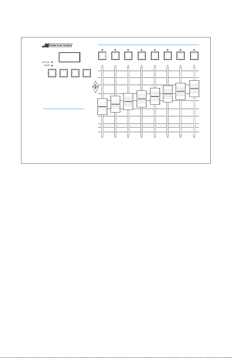
Front Panel Controls
TOUCH
GROUP SNAP
P 1
P 1
SHIFT
PROG DOWN NULL UP
FaderMaster
PROFESSIONAL
MIDI Automation Controller
UNIT# CHAN
PARM CHAN PARM# MIN MAX SPEED/BM GROUP MERGE
ENABLE
MUTE
WRITING
MODE
12345678
NULL
12345678
PROTECT
From left to right we have:
PROG
Program button. Selects one of the Program Modes, to change
the settings of FaderMaster Pro.
Pressing PROG repeatedly cycles through the following:
• FADER LED On: Fader Program Mode
• BUTTON LED On: Button Program Mode
• FADER LED Flashing: Foot Pedal Program Mode
• BUTTON LED Flashing: Foot Switch Program Mode
In the Automation Banks (A 1 through A 8),
Pressing PROG toggles the FADER LED on and off.
To exit the Program Mode,
Press PROG until both FADER and BUTTON LEDs are off.
6
Page 7

DOWN
Steps back down through memory banks.
For example, if the display says P 2,
Press DOWN, display then says P 1.
Hold DOWN while moving any fader to quickly access any
bank.
NULL (SHIFT)
Holding NULL while moving a fader allows you to move the
fader without any MIDI data being sent. This allows you to preposition the fader to start at a specific MIDI value.
NULL is also used in the A Banks along with the NULL LEDS, to
avoid unexpected jumps in level while editing a mix.
Observe the NULL LEDs to determine if the fader needs to be
raised or lowered to match previously recorded MIDI data.
The NULL (SHIFT) button also accesses SHIFTED functions.
These are indicated in blue legends on the front panel.
UP
Steps up through memory banks.
For example, if the display says P 1,
Press UP, display then says P 2.
Hold UP while moving any fader to quickly access any bank.
MODE (that is, SHIFT and UP)
In the Automation Banks, selects what the buttons above the
faders do. These buttons are either "Enables" or "Mutes".
Press an Enable to turn a fader on or off.
Press a Mute to send a MIDI Controller with a zero value.
The current function of the buttons is indicated by a dash in
the seven-segment display next to the word ENABLE or MUTE.
7
Page 8

Buttons Above the Faders
When one of the P Banks has been selected on FaderMaster
Pro, pressing a button sends any kind of MIDI command.
When one of the A Banks has been selected on FaderMaster
Pro, pressing these buttons send MIDI Controller commands
with a zero value to act as audio Mutes.
Also in the A Banks, press these buttons to Enable a fader to
send MIDI Controller commands.
When in one of the Program Modes (selected by the PROG
button), the buttons above the faders are used for assigning the
kind of MIDI command (parameter) that a given control will
send, certain other attributes of the fader. The kinds of
parameters and attributes selected by the buttons are as
follows:
PARM
In Program mode, hold PARM while moving a fader to select
the parameter, that is, the type of MIDI Command, that a
control will send.
Choices include: Notes, Controllers, Program Change, Pitch
Bend, and After touch.
CHAN
In Program mode, hold CHAN while moving a fader to select
the MIDI channel, 1 through 16, that a control will send.
PARM#
In Program mode, hold PARM# while moving a fader to select
the parameter number, that is, the Controller number or Note
number, that the control will send.
8
Page 9

MIN
In Program mode, hold MIN while moving a fader to select the
minimum value that a control will send.
MAX
In Program mode, hold MAX while moving a fader to select the
maximum value that a control will send.
SPEED/BM
For Faders or Foot Pedal,
In Program mode, hold SPEED/BM while moving a fader to
select the speed of the MIDI data sent out. Select 1 through 4.
(4 is the fastest.)
For Buttons or Foot Switch,
In Program mode, hold SPEED/BM while moving a fader to
select the Button Mode, either Momentary, Latched, or Fader.
Momentary: Button sends a MIDI command when
pressed, using MAX as its value. Sends another MIDI
command when released, using MIN as its value.
The LED above button is momentary, that is, it is only on as
long as the button is held down.
Latched: Button sends a MIDI command when pressed,
using MIN as its value, and another message when pressed
again, using MAX as its value.
The LED above button is latched, that is, it turns on with the
first press and off with the second press.
Fader Value: Button sends a MIDI command when
pressed. When released, it sends the same command using
the fader position as its value.
The LED above button is latched, that is, it turns on with the
first press and off with the second press.
9
Page 10

TOUCH (that is, SHIFT and SPEED/BM)
In the Automation Banks, turns on FaderMaster Pro’s unique
Touch-Sensitive Automatic Punch In.
Press SHIFT TOUCH to toggle between Touch On (t[K) and
Touch Off (0FF).
TOUCH is used to effect seamless edits to sequencer tracks
consisting of controller commands.
When a fader is moved, the fader will not send any MIDI
Controller commands until the fader level exactly matches the
level of previously recorded Controller commands.
GROUP
In the P Banks, in Program Mode, hold GROUP while moving a
fader to select a group master for a given fader.
Faders may be grouping in one of three different group modes.
Exit Program Mode, then hold SHIFT and GROUP while
moving a fader to select the group mode.
Absolute Grouping: Fader values match the master.
Relatively Scaled Grouping: Fader values are scaled
based on how much the master has moved with respect
to the fader throw. That is to say, when you fade the
master, all the values reach their minimum value at the
same time.
Offset Grouping: Fader values are offset by the value of
the master, as referenced to the center of the master's
throw. That is to say, the value of the master is added to
or taken away from the faders that are part of the group.
PROTECT (that is, SHIFT and PARM#)
Hold SHIFT and PROTECT and move any fader to turn Protect
on and off. When display indicates PRO, FaderMaster Pro may
not be reprogrammed.
10
Page 11

MERGE
In the P Banks, in Program Mode, hold Merge while moving a
fader to select the Merge mode for that fader.
Each fader within a bank may have a different Merge mode.
Merge On: MIDI commands pass through
Merge Off: MIDI coming into FaderMaster Pro is checked
to see if any fader is programmed to send out the same
commands. MIDI passes through FaderMaster Pro, unless a
fader is programmmed to send the same commands.
Merge Conditional: MIDI commands pass through
FaderMaster Pro. MIDI coming into FaderMaster Pro is
checked to see if any fader is programmed to send out the
same commands.
The MIDI data is allowed to pass through to the MIDI out,
until you move a fader. Then, that MIDI data is selectively
filtered out. This is used to replace previously recorded
tracks of MIDI data.
SNAP (that is, SHIFT and MERGE)
Holding the SHIFT button and pressing SNAP sends out a
“Snapshot” consisting of MIDI data representing the current
position of the faders.
Used at the beginning of a sequence to establish the initial
levels of a mix.
FaderMaster Pro.
NULL LEDS (Used With Automation Bank)
Compares the position of the last fader moved with the value
of MIDI data coming into the FaderMaster’s Pro’s MIDI input.
Lets the user know if the fader is above (up arrow) or below
(down arrow) the level of the MIDI data coming into
FaderMaster Pro.
Used to assist in seamless punch in type edits of previously
recorded MIDI data for mix editing.
11
Page 12

UNIT# (SHIFT and PARM)
Sets System Exclusive Unit ID Number. This is only used in
conjunction with the optional FaderMaster Pro Remote
Software. Allows software to independently communicate with
more than one FaderMaster Pro.
Hold SHIFT UNIT# while moving any fader to select a number
from 0 to 15.
This allows the FaderMaster Pro Remote software to program
and back up as many as 16 FaderMaster Pros.
CHAN (SHIFT and CHAN)
Sets MIDI Channel of FaderMaster Pro so FaderMaster Pro can
respond to MIDI Program Change commands.
Hold SHIFT and CHAN while moving any fader to select a
MIDI channel from 1 to 16.
Dashes in the display indicate that the reception of program
changes has been disabled.
12
Page 13
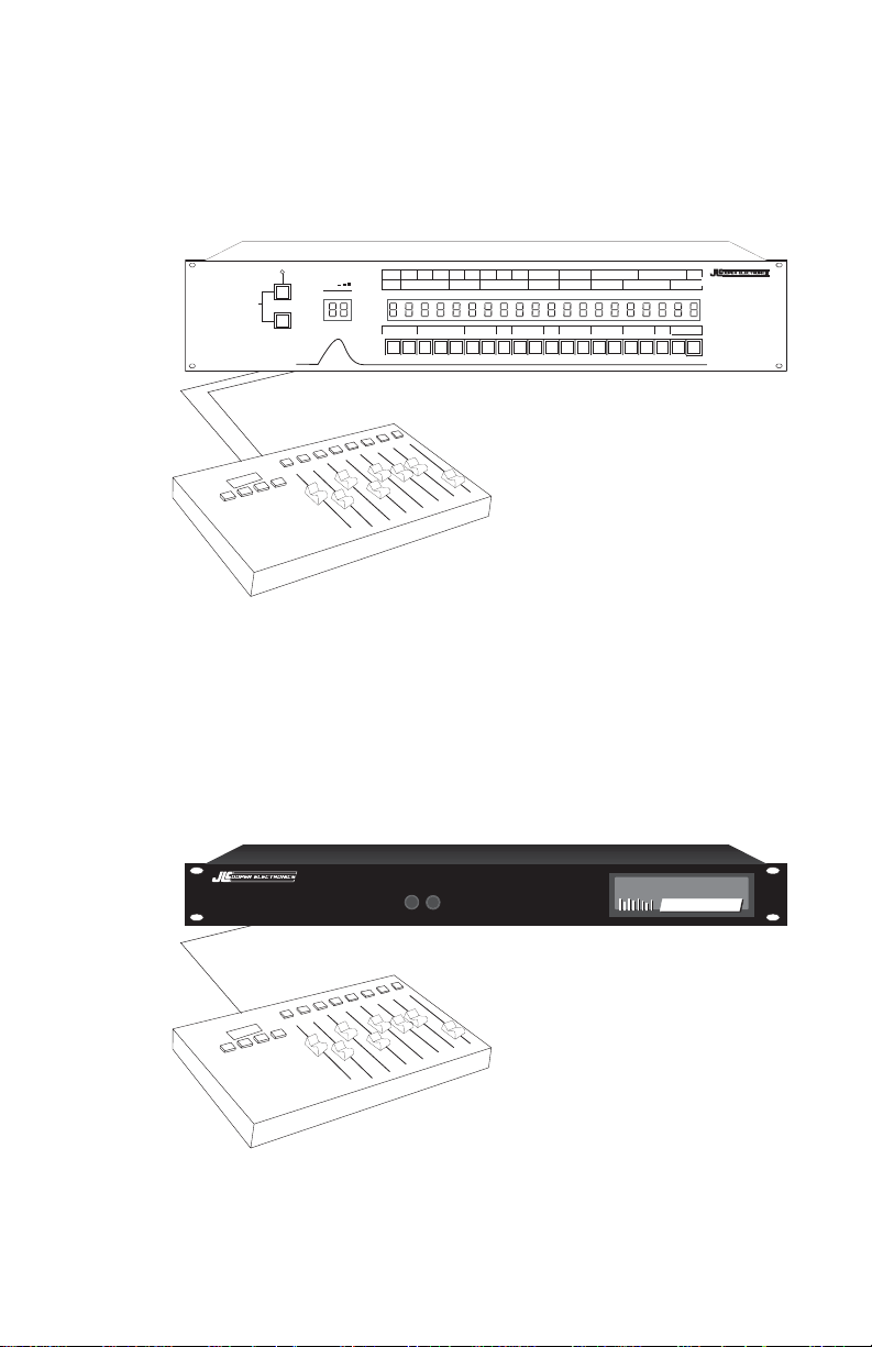
Hookup
➤ For Total Studio Control:
Connect the MIDI Input and Output of the FaderMaster Pro to
a MIDI patch bay, such as JLCooper’s Synapse or a computer
WRITE
PANIC
MODE
Synapse
PROC
PROGRAM
IN PORT CTRLNOTE AFT MERGEPGM
132
OUT PORT PGM NUMBER
1234567891011 12 13 14 15 16 17 18 19 20
BEND RTIME SYSEX SCOM CHAN FILTER
LOW NOTE HI NOTE CHANNEL TRANSPOSE
CHANNEL STEP NUMBER REMOTE OUT SCOPE
CHAN BUMP
REMOTE IN
VELOCITY MINIMUM
VELOCITY MAXIMUM
REMOTE CH
MIDI ROUTING SYSTEM
interface with built-in patch bay.
➤ For Direct Control of Signal Processors, Synthesizers, or
MIDI Controlled VCA’s such as JLCooper's MixMaster:
Connect the MIDI out of FaderMaster Pro to the MIDI in of the
device that you want to control.
MixMaster
MixMaster
MIDI Controlled Mixer
13
Page 14
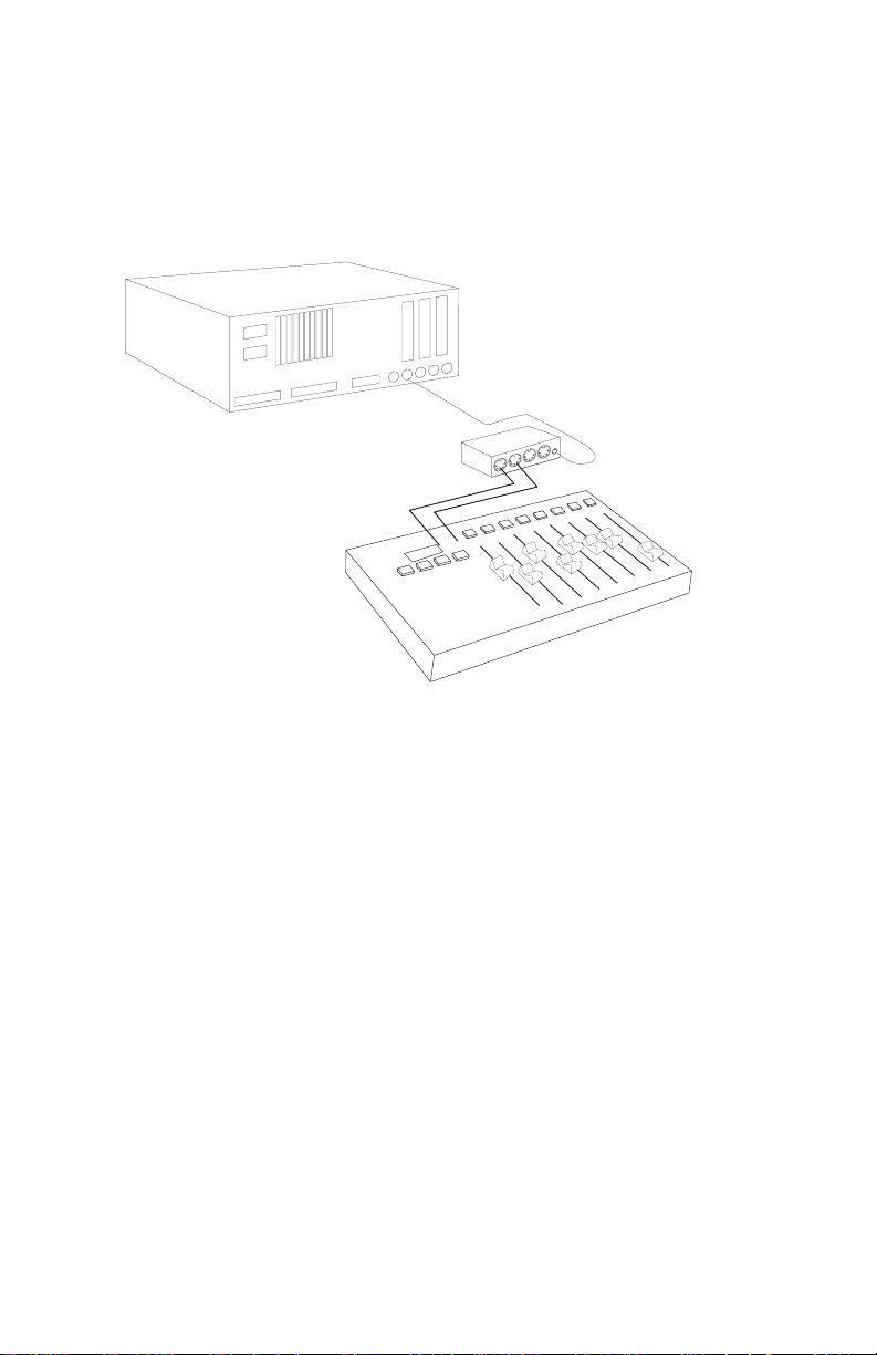
➤ For Sequencer Automation:
Connect the MIDI out of FaderMaster Pro to the MIDI In of the
Sequencer or Computer interface.
Connect the MIDI out of the sequencer or computer interface
to the MIDI in of FaderMaster Pro.
Computer
Interface
Warning!
Turn the sequencer's "Thru feature" off when
connecting FaderMaster Pro in this manner.
FaderMaster Pro has a MERGE feature. This feature simply
passes data from the MIDI In to the MIDI out.
You could potentially create an infinite MIDI loop if you
connect two MIDI cables to FaderMaster and leave the
sequencer's "Thru" turned on.
"Thru" on the sequencer may also be called Echo, MIDI Echo,
Direct Echo, Patch Thru, etc.
(More specific information on how to avoid this kind of loop is
given in the chapter on mixing with the Automation Banks.
See page 43.)
14
Page 15
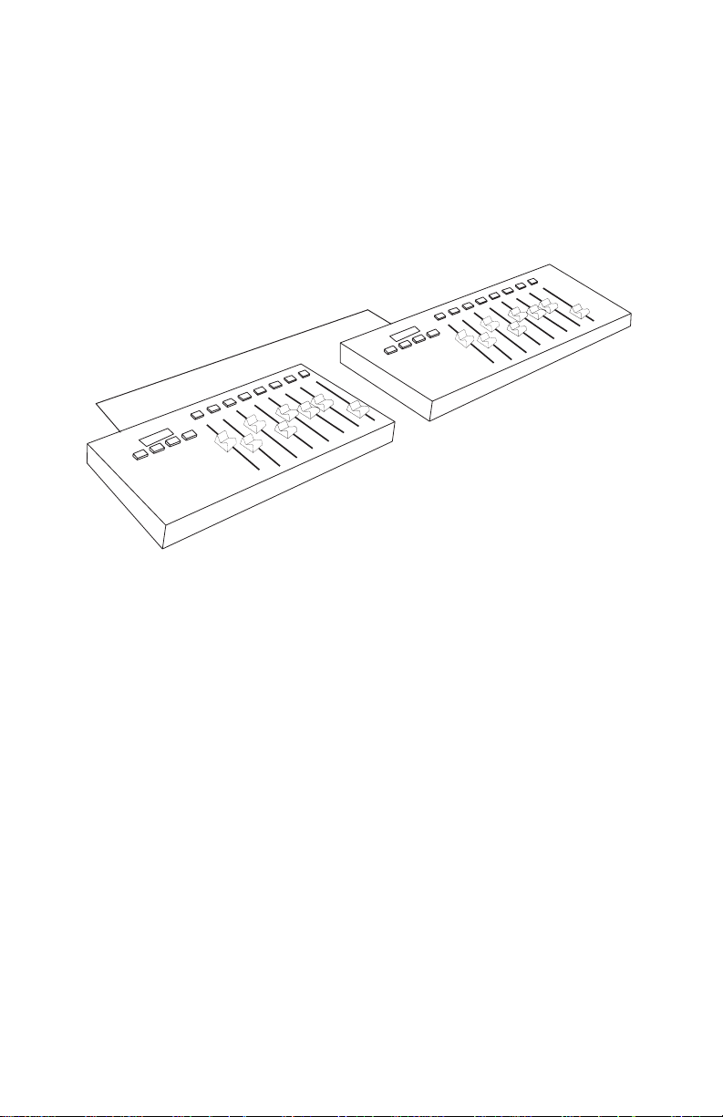
➤ Hooking Up Several FaderMaster Pros
Multiple FaderMaster Pros may be chained together to form a
larger console.
Simply connect the MIDI Out of the first FaderMaster Pro to the
MIDI In of the next FaderMaster Pro.
15
Page 16

Bank Selection
FaderMaster Pro’s memory is organized into three sets or
“Banks” of programs.
(In developing FaderMaster Pro, we decided to organize the
memory into “Banks” as opposed to “Savings and Loans”.
Otherwise you might come back the next day and find them
missing or renamed.)
P 1 through P 20 User Programmable Banks
A 1 through A 8 Automation Banks
F 1 through F 50 Factory Banks
Step up through the banks one at a time by pressing UP.
For example, if the display says P 1,
Press UP, display then says P 2.
Step down through the banks one at a time
For example, if the display says P 2,
Press DOWN, display then says P 1.
Rapidly scroll through all the banks by holding either
UP or DOWN while moving any fader.
Stop moving the fader at the desired bank.
As you step through banks P 1 through P 20, FaderMaster Pro
sends out a short system exclusive MIDI command for each
bank change, informing other FaderMaster units to also change
banks.
Selecting a new bank means that you are selecting entirely
different MIDI assignments for the faders and buttons.
This means that you can use FaderMaster Pro for multiple
applications at the same time, simply by changing banks.
by pressing DOWN.
16
Page 17

For Example
Say that P 1 has been programmed to send MIDI controllers to
alter the parameters on a signal processor, such as the Alesis
QuadraVerb 2.
Say that P 2 has been programmed to send MIDI controllers
(on a different MIDI channel) to a adjust a MIDI Graphic
Equalizer, such as the DOD MEQ28.
First Select P 1. Then, move the faders to change the sound
characteristics on the QuadraVerb 2.
Press UP to select P 2. Then, move the faders to change the
EQ curve on the MEQ unit.
Press DOWN again to select P 2 to adjust the QuadraVerb, etc.
This allows you to have immediate live control of multiple
signal processors. (Without, obviously, walking over to the
rack and fiddling with parameters one at a time with an LCD
menu.)
In addition, the MIDI output of FaderMaster Pro may be
recorded onto a sequencer, so that the signal processor
changes may be automated and occur simultaneously.
17
Page 18

User Programmable Banks P 1 - P 20
The twenty User Programmable are indicated in the display as
P 1 through P20.
Each of the eight faders and eight buttons may send a different
kind of MIDI message.
This is the most flexible bank, when your application calls for
complex sets of different kinds of MIDI commands.
If, however, you plan on using FaderMaster Pro mostly for
automation, (such as sequencer mixing, digital audio
workstation mixing, simple signal processor control, etc.),
turn first to the chapter on the Automation Banks, page 41.
The Automation Banks are much easier to program than the
User Banks. In the Automation Banks, you only set one
fader, and all the rest of the faders and buttons are
automatically assigned to sequential controller numbers.
From the front panel of FaderMaster Pro, you can make each
fader and button send the following MIDI commands or
parameters (called PARM): Continuous Controller, Notes, After
touch, Pitch Bend, and Program Changes.
With the optional FaderMaster Pro Remote software, you can
also make the faders and buttons send MIDI System Exclusive
commands.
For each fader and button, you may select the MIDI channel,
the controller or note number, and minimum and maximum
values.
For faders, you may set the speed of the MIDI output and
whether any fader is grouped to another fader.
For buttons, you may set whether the button acts momentarily
or push on / push off.
18
Page 19

Programming FaderMaster Pro
Programming is done one of the programming modes,
accessed by simply pressing the PROG button.
First, before attempting to make any changes to the way
FaderMaster Pro is programmed,
Make sure that the PROTECT feature is OFF.
(The PROTECT feature works like the safety tab on a cassette
or diskette, to prevent you from accidentally changing the
memory of FaderMaster Pro.)
Hold SHIFT and PROTECT observe the Protect status.
Move any fader to turn Protect on and off.
When Protect is off, the display indicates 0FF.
When Protect is on, the display indicates Pro.
Entering Programming Modes:
To program the faders,
press the PROG button once so that the FADER LED is lit.
To program the buttons,
press the PROG button again so that the BUTTON LED is lit.
To program the foot pedal input,
press the PROG button again so that the FADER LED flashes.
To program the foot switch input,
press the PROG button again so the BUTTON LED flashes.
Exiting Programming Modes:
To exit the programming mode,
press the PROG button again until both LEDs are off.
19
Page 20

Programming Faders (In General)
➤ First select a Programmable User Bank number,
P1 through P20.
Use the UP or DOWN buttons to step to the desired program
number, or, hold UP or DOWN while moving any fader and
stop moving the fader when the desired number is reached.
➤ Enter Fader Program mode.
Press the PROG button once so that the FADER LED is lit.
➤ Press and hold a button corresponding to the desired
parameters or attributes while moving a fader.
➤ Exit Fader Program mode.
Press the PROG until both FADER and BUTTON LEDs are off.
Simple Example
To make fader 1 send MIDI Controller data on MIDI channel 4
when moved,
❏ Enter Fader Program mode. (Press PROG once.)
❏ Move fader 1 while holding the PARM button
until Co is displayed.
❏ Move fader 1 while holding the CHAN button
until 4 is displayed.
❏ Exit Fader Program mode.
More programming details are provided in the following pages.
20
Page 21

Programming the Faders (In Detail)
Here are the specifics parameters and attributes that may be
selected for each fader. (Remember that these settings may
only be reviewed and edited in Fader Program mode.)
➤ PARM
Hold the PARM button while moving a fader to select whether
the fader will send Notes (No), Controllers ([o), Program
Change (P[), After Touch (At) or Pitch Bend (Pb).
➤ CHAN
Hold the CHAN button while moving a fader to select what
MIDI channel the fader will send on, 1 through 16.
➤ PARM#
Hold the PARM# button while moving a fader to select the
what Controller Number or Note Number the fader will send, if
the fader has been assigned to send Controllers or Notes.
➤ MIN
Hold the MIN button while moving a fader to select the
minimum value that the fader will send when it is moved to the
bottom of its travel.
➤ MAX
Hold the MAX button while moving a fader to select the
maximum value that the fader will send when it is moved to
the top of its travel.
Notice
If you set a faders minimum value higher than its
maximum value, the fader will operate reversed.
21
Page 22

MIN and MAX Application Example
A fader that sends MIDI Volume commands may have a
minimum of 0 and a maximum of 127.
To perform a crossfade, set another fader with a minimum of
127 and a maximum of 0. When you bring up the two faders,
one will effect a fade in while the other effects a fade out.
You may also group these two faders (discussed next).
Moving up one fader would send Volume commands that are
increasing (on one MIDI channel), at the same time as Volume
commands (on a different MIDI channel) that are decreasing.
A fader that sends MIDI Program Change commands may have
a minimum of 1 and a maximum of 32, if you are trying to
restrict the available programs in a signal processor to a given
class of sounds.
(You want to make sure you stick with a family of related hall
sounds, and never accidentally select the ever-so-useful
flanged-leslie-reverse-gated-reverb.)
➤ SPEED/BM
Hold the SPEED button while moving a fader to select how fast
the fader will send out MIDI data. The speed is represented by
a number 1 through 4. 1 is the slowest and 4 is the fastest.
Generally speaking, choose the fastest setting (4) for the
smoothest control for mixing applications. Choose the slowest
setting (1) for sending program changes so you will have more
control.
22
Page 23

➤ Grouping
In the P Banks, faders may be grouped.
To group a fader means that you assign some number of faders
to be controlled by another fader called a "group master fader".
When you move a group master fader, FaderMaster Pro sends
out MIDI commands just as if you simultaneously moved all of
the faders assigned to the group master fader.
In other words, moving one fader sends out multiple MIDI
commands as if several faders were being moved.
An Application Example
Say that the eight faders have been programmed to send
MIDI Volume (MIDI Controller #7) on channels 1 through 8.
You could make fader 4 a “group master fader” by assigning
faders 1 through 3 to group master 4.
You could make fader 8 a “group master fader ” by assigning
faders 5 through 7 to group master 8.
The result would be that if you
Move this Fader: FaderMaster Pro Sends:
1 MIDI Volume on Channel 1
2 MIDI Volume on Channel 2.
3 MIDI Volume on Channel 3.
4MIDI Volume on Channels 1 through 4.
5 MIDI Volume on Channel 5.
6 MIDI Volume on Channel 6.
7 MIDI Volume on Channel 7.
8MIDI Volume on Channels 5 through 8.
Moving a master results in data being sent for the master and
all the faders assigned to the master.
23
Page 24

➤ To Assign Groups
Enter Fader Program Mode by pressing PROG until the FADER
LED is lit.
Hold the GROUP button while moving a fader to select the
master for that fader.
For the example just given, hold GROUP and
move fader 1 until a "4" is displayed,
move fader 2 until a "4" is displayed,
move fader 3 until a "4" is displayed,
move fader 5 until a "8" is displayed,
move fader 6 until a "8" is displayed,
move fader 7 until a "8" is displayed,
Exit Fader Program mode.
Group Modes
FaderMaster Pro operates in one of three Group modes:
➤ Absolute
➤ Relatively Scaled
➤ Offset
Choose one of the three Group Modes by pressing SHIFT
GROUP and move any fader, the display indicates:
0ff0ff
0ff
0ff0ff
re1re1
re1
re1re1
absabs
abs
absabs
Group Modes may be selected "on the fly", while you are
actually operating FaderMaster Pro. You do not need to enter
Fader Program mode.
24
Page 25

Group Modes Demonstrated
For the examples given below, the pictures represent the sort
of images you would be likely to observe on sequencer
software with on-screen moving faders.
While any fader can be a group master, for sake of these
examples say that faders 1 through 7 are assigned to group
master 8.
Absolute Grouping
The faders assigned to the master take on the value of the
master. This is true regardless of the position of the faders
assigned to the master.
Before Assigning Groups: After Moving the Master:
Relatively Scaled Grouping
The faders assigned to the master are proportionally scaled to
the master, so that they will all reach the bottom of their throw
at the same time.
Before Assigning Groups:
Moving the Master Down: Master at Bottom of Throw:
25
Page 26

Offset Grouping
The faders assigned to the master are offset by the position of
the master.
Faders assigned to the master are offset positively as the master
is raised above the mid-point.
Faders assigned to the master are offset negatively as the
master is lowered below the mid-point.
Before Assigning Groups:
Master Above Mid-point: Master Below Mid-Point:
➤
➤
26
Page 27

MERGE Modes
In the P Banks, each fader may be individually assigned to one
of three Merge modes:
➤ Merge Off
➤ Merge On
➤ Merge Conditional
Before describing what the differences are between these
modes, and how to assign the faders to these modes, a general
definition would be helpful here:
Merging means the ability of FaderMaster Pro to pass MIDI
data from its MIDI In to its MIDI Out.
A simple example of merging is this:
Connect the MIDI out of a keyboard to the MIDI In of
FaderMaster Pro.
Connect the MIDI out of FaderMaster Pro to a tone module.
When you play the keyboard, the MIDI data comes out of
the keyboard, goes into the FaderMaster Pro, and comes
out of FaderMaster Pro. When you move a fader, of course,
MIDI data also comes out of FaderMaster Pro.
The feature is called Merging (instead of calling it ECHO or
Soft Thru as it is called on sequencers) to make it clear that
the FaderMaster Pro is merging or combining the MIDI data
coming into FaderMaster Pro with the MIDI data produced
by FaderMaster Pro, as a result of moving the faders, pedal,
pushing buttons, or foot switch.
FaderMaster Pro, while merging, can selectively filter out
certain kinds of MIDI data, to make sequencer mixing and
signal processor control more predictable.
27
Page 28

Here’s how it works:
After you have recorded controller data on your sequencer,
you may want to edit that data. FaderMaster Pro’s special
MERGE modes are designed to simplify the editing of
Continuous Controller data.
The procedure will be to play the previously recorded data
from the sequencer into FaderMaster Pro, while re-recording
the corrected data coming out of FaderMaster Pro onto a new
sequencer track. This is a fairly fail-safe method, in that you
need not erase the old MIDI controller track until the new track
has been proven to give audibly pleasing results.
(All this assumes, of course, that your sequencer has the ability
to easily select which tracks are in playback and which are in
record status. That may be difficult on certain hardware
sequencers.)
Merge Modes Defined:
Merge Off
This mode is used for completely replacing a track of
Controller data. For example, say you have used FaderMaster
Pro to record some volume tracks on a sequencer. You may
want to completely redo several of those tracks while leaving
the others intact.
Data coming into FaderMaster Pro is first examined by the
internal microprocessor. If Controller data comes into
FaderMaster Pro with the same Parameter Number and MIDI
channel that a fader is set for, that data is not passed through.
The data may then be replaced by new data when a fader is
moved. It is this new data that is recorded onto a new
sequencer track.
28
Page 29

Merge On
Normally, MIDI data received by FaderMaster Pro is
“unconditionally merged” with fader commands. That is, any
data that comes into FaderMaster Pro goes right back out the
MIDI output, merged with the data produced by moving a
fader.
Conditional Merge
This mode is used for replacing sections of a track of Controller
data. For example, say you have used FaderMaster Pro to
record some volume tracks on a sequencer. You may want to
redo certain parts of those tracks while leaving the rest intact.
Data coming into FaderMaster Pro is first examined by the
internal microprocessor.
If Controller data comes into FaderMaster Pro with the same
Parameter Number and MIDI channel number that a fader is set
for, that data is passed through until a fader is moved.
Then the volume data will be replaced by new data from the
fader being moved. It is this new data that is recorded onto a
new sequencer track.
Momentarily pressing SHIFT and PROG will once again allow
data to pass through for that fader (i.e. effect a punch out),
until the fader is moved again.
In other words, this mode allows the momentary interruption
of the flow of Controller data through FaderMaster Pro.
During that interruption, new MIDI data may be inserted by
moving the faders.
29
Page 30

➤ Assigning Merge Modes
To view or change the merge assignment for a given fader, first
make sure you are in PROG Mode, and the Fader LED is on
steadily (not flashing.)
Press MERGE. The display will show one of the following:
0n = Merge On.
All data is passed through FaderMaster Pro and merged with
fader data.
0FF = Merge Off.
Data coming into FaderMaster Pro is examined. If the fader is
set to Merge Off, and if Controller data comes into FaderMaster
Pro with the same Parameter Number and MIDI channel that
the fader is set for, that data is not passed through.
[on = Conditional Merge.
The data coming into FaderMaster Pro is examined as
described above. Merging takes place until the corresponding
fader is moved. At that point the data coming in is not passed
through, but is replaced by fader data. A momentary push of
SHIFT and PROG button allows MIDI data to be merged again.
In the User Programmable Banks P1 through P20, you set the
merge for each fader by pushing the MERGE button and
moving the fader.
To exit the programming mode, press the PROG button again
until both LEDs are off.
30
Page 31

Programming the Buttons
To program the buttons, press the PROG button until the
BUTTON LED is lit.
Programming a button is easy.
But it is not immediately obvious.
(One might be inclined to ask the question, "how do you
program the buttons, since the buttons themselves are used for
selecting the parameters and attributes of the buttons?")
Here is the answer: The buttons are programmed exactly like
the faders are programmed. You select which button you are
programming by moving the fader under the button.
A Simple Example
To make button 1 send MIDI Controller 7 with a value of 0
when pressed,
❏ Enter BUTTON programming mode by pressing the
PROG button until the BUTTON LED is lit.
❏ Move fader 1 while holding the PARM button
until [o is displayed.
❏ Move fader 1 while holding the PARM# button
until 7 is displayed.
❏ Exit BUTTON program mode by pressing the PROG
button until both LEDs are not lit.
Now, pressing button 1 will send a MIDI Controller 7 with a
value of 0 when pressed. Since MIDI Controller 7 is MIDI
volume, pressing the button will act as an audio mute.
Remember, you choose the button number that you want to
program by moving the corresponding fader below the button.
31
Page 32

Here is how to set the various parameters and attributes of the
buttons, in the P banks and in Button programming mode:
➤ PARM
Hold the PARM button while moving a fader to select whether
the button will send Notes (No), Controllers ([o), Program
Change (PG), Pitch Bend (PB). Notice that Notes are always
sent as Note On, Note Off pairs with each button press.
➤ CHAN
Hold the CHAN button while moving a fader to select what
MIDI channel the button will send on, 1 through 16.
➤ PARM#
Hold the PARM# button while moving a fader to select what
Controller Number or Note Number the button will send, if the
button has been assigned to send Controllers or Notes.
➤ MIN
Hold the MIN button while moving a fader to select the
minimum value that the button will send.
➤ MAX
Hold the MAX button while moving a fader to select the
maximum value that the button will send.
➤ SPEED/BM (BUTTON MODE)
Hold the SPEED/BM button while moving a fader to select
whether the button’s action is
--- Momentary
Button sends MIN value when pressed and MAX value
when released.
L[K Latched
Button sends MIN value when pressed.
Button sends MAX value when pressed again.
FAd Uses Fader Value
Button sends MIN value when pressed. Sends value equal
to fader position when pressed again.
(Group and Merge are not assignable to the buttons.)
32
Page 33

Programming the Foot Pedal
The foot pedal input accommodates a user-supplied foot
pedal. (Most pedals with tip-ring-sleeve plugs will work.)
A Foot Pedal is programmed just like the faders.
It is programmed in Foot Pedal Program mode, which is
selected by pressing the PROG button until the FADER LED
flashes.
In Foot Pedal Program mode, select the desired parameter or
attribute button while moving fader 1.
Exit Foot Pedal Program mode by pressing the PROG button
until both LEDs are not lit.
Programming the Foot Switch
The foot switch input accommodates a user-supplied
momentary foot switch.
Both "normally open" and "normally closed" type foot switches
will work. Plug in the foot switch before powering on
FaderMaster Pro, so the internal microprocessor has the
opportunity to "look at" the foot switch to determine which
kind it is.
The foot switch is programmed in Foot Switch Program mode,
which is selected by pressing the PROG button until the
BUTTON LED flashes.
In Foot Switch Program mode, select the desired parameter or
attribute button while moving fader 1.
33
Page 34

Like the buttons, use the SPEED/BM (Button Mode) button to
choose how the foot switch will behave.
Hold the SPEED/BM button while moving a fader to select
whether the foot switch action is
--- Momentary
Foot Switch sends MIN value when pressed and MAX value
when released.
L[K Latched
Foot Switch sends MIN value when pressed. Button sends
MAX value when pressed again.
FAd Use Fader Value
Foot Switch sends MIN value when pressed. Sends value
equal to Foot Pedal position when pressed again.
Like the buttons, you cannot set GROUP or MERGE.
Exit Foot Switch Program mode by pressing the PROG button
until both LEDs are not lit.
34
Page 35

Snapshot Function (In the P Banks)
FaderMaster Pro can send out a burst of MIDI commands
called a Snapshot. The MIDI commands represent the position
of each fader in the currently selected P Bank.
For example, suppose each fader is programmed to send pitch
bend commands on different MIDI channels. Sending a
Snapshot would result in eight different pitch bend commands
going out. This could be used to quickly transpose a rack of
tone modules. And its done with a single button push, rather
than moving 8 faders, one at a time.
➤ To send a Snapshot, hold SHIFT and press SNAP.
Using the Null feature (next page), each fader may be moved
into position without any MIDI data being sent out. Then,
when you are ready, send the Snapshot and the MIDI
commands for eight faders will all go out at the same time.
35
Page 36

Null Button (In the P Banks)
There may be situations where you wish to move a fader to a
certain position, without sending any MIDI commands.
Using the Snapshot feature (described on the previous page),
you may want FaderMaster Pro to send out specific values of
MIDI commands, without having to move the faders and send
out all sorts of intermediate values.
For example, if you just want a single MIDI Program Change to
go out, say, 48, you may not want to move the fader and end
up sending 1 through 48.
Hold the NULL button before moving a fader, and keep it held
down. Then, when you move the fader, FaderMaster Pro will
not send out any MIDI commands.
You can still observe the current value of the fader in the
display.
Then, when you are ready to send MIDI commands, release
the NULL button.
To send a MIDI command, either move a fader a little bit, or
press SHIFT SNAP to send a Snapshot of the current values of
all eight faders.
The NULL LEDs are use in the A Banks for automated mixing,
and are not used in the P Banks.
36
Page 37

Automation Banks A1
through A8
Introduction
FaderMaster Pro’s Automation Banks allow you to control up
to 65 channels of automation. Applications include control of
sequencers or hard disk based digital audio workstations with
moving fader graphics, MIDI-controlled audio mixers (such as
JLCooper’s MixMaster), MIDI controlled lighting systems, and
more.
The automation banks are engineered to be both simple and
powerful.
First of all, they are very simple to program. Simply select one
MIDI channel, and one controller number. FaderMaster Pro
automatically assigns the controller numbers for all the faders,
each fader sending the next higher controller number.
For example,
In Bank A 1, moving faders 1 through 8 may send MIDI
controller numbers 1 through 8.
In Bank A 2, moving faders 1 through 8 may send MIDI
controller numbers 9 through 16.
Secondly, the automation banks borrow the powerful features
found in JLCooper’s mixing console automation systems.
With our unique “Touch” feature, you can seamlessly edit fader
moves simply by moving the fader.
FaderMaster Pro will get ready to “write the fader”, that is, start
sending MIDI controller commands, as soon as it detects that
the fader is moved. But it will not actually begin sending the
MIDI commands until the fader is moved across a “null point”,
that is, until the fader is “lined up” with previously recorded
37
Page 38

This Touch feature allows any MIDI sequencer to behave like a
six-figure automated mixer with touch-sensitive faders. There
is no guessing, and no button that needs to be pressed at an
exact moment. You have the feel of an automated mixer, that
lets you grab any fader at any time and begin editing a track of
controller commands.
Really Important
At this point, you may be tempted to select an Automation
Bank and move a fader to see what happens. No problem,
except that when you move a fader you may notice right away
that no MIDI data comes out of FaderMaster Pro!
In the Automation Bank, the faders do not send MIDI data until
you “Write Enable” them, by pressing the button above the
fader.
To make automation really usable and editable, you need the
power of being able to turn faders on and off, and this is done
with the buttons above the faders.
And, yes, the buttons above the faders are also used for
muting. This is all explained in detail in this chapter, so please
be patient.
Once you get going, you will find it very natural to work with,
but at the outset it could be confusing, so we recommend that
you read this chapter carefully before trying to complete a
project while under time pressure.
38
Page 39

Bank Limit
Suppose you are using FaderMaster Pro to control 24 channels
of automation, such as 24 channels of MIDI controlled VCAs,
or 24 on-screen faders on a sequencer or HD recorder.
That means that most of the time you will be only using
FaderMaster Pro’s Automation Banks A 1, A 2 and A 3.
Ideally, you should be able to instantly switch between
Automation Banks A1, A 2 and A 3, with a single button push,
without having to worry about accidentally selecting some
irrelevant bank.
A method has been provided to quickly switch between your
Automation Banks, its called “Bank Limit”.
Setting a Bank Limit means that, as long as you are using the
Automation Banks, pressing UP or DOWN will simply cycle
through the valid Automation Banks, skipping the banks
outside of the limit.
For example, setting the Bank Limit to A 3 means that
Pressing UP will result in FaderMaster Pro cyclically recalling
A 1, A 2, A 3,
A 1, A 2, A 3, etc.
Pressing DOWN will result in FaderMaster Pro cyclically
recalling
A 3, A 2, A 1,
A 3, A 2, A 1, etc.
39
Page 40

Setting Bank Limit
To set the Bank Limit in the Automation Banks,
press UP or DOWN until the desired highest Automation Bank
is displayed, and keep the button pressed.
While holding the button , press the other bank select button.
For example, to set the Bank Limit to A 3,
❏ Select A 1 Display says A 1
❏ Press UP Display says A 2
❏ Press UP again and do not release it
Display says A 3
❏ Press DOWN.
❏ Release both buttons. Display says A 3.
While the Bank Limit is set, there is a decimal point LED in the
A banks, in this case A 1. A 2. A 3.
Escaping from the Bank Limit
Even after setting a Bank Limit, you can still select any
FaderMaster Pro Bank, by holding either UP or DOWN while
moving a fader. So you can use the P banks P 1 through P 20,
the F Banks, even A banks outside the limit.
But the LIMIT is stored in memory, until you choose to remove
it. For whenever you select a Bank within the range of the
limit, pressing UP or DOWN again returns you to cyclic
stepping through only the limited automation banks.
To completely turn off the Bank Limit:
Press DOWN and UP at the same time and observe that the
decimal point LED turns off as you release both buttons.
40
Page 41

Automation Hookup Considerations
The minimal hookup is, of course, a single MIDI cable from the
MIDI Output of FaderMaster Pro into the MIDI Input of
whatever you are controlling, typically a MIDI interface to a
computer.
To take advantage of FaderMaster Pro’s mix editing features
(Null, Touch), FaderMaster Pro must be able to receive MIDI
from the output of a MIDI sequencer. That means that a MIDI
cable is connected from the MIDI out of a computer MIDI
interface to the MIDI In of FaderMaster Pro.
Avoiding MIDI Loops
A few things need to be considered in order to have success
without too much tinkering and troubleshooting.
Remember that your sequencer has a function called “thru”, (or
sometimes “soft thru” or “MIDI echo” or “direct echo”). Its
purpose is to pass MIDI data from the input of the sequencer to
the output. Most people leave it turned on most of the time. So,
when you play a keyboard for example, the notes from the
keyboard get recorded on the sequencer and also pass through
the sequencer, so you can hear the part being played on a tone
module.
FaderMaster also has the ability to pass MIDI data from its MIDI
Input to its MIDI output.
So, you can see that if you leave the sequencers “thru” feature
turned on, and also hook up two MIDI cables to FaderMaster
Pro, you’ve formed a MIDI loop.
This is something to avoid, since loop usually results in (at
best) the sequencer hanging-up until a cable is pulled and (at
worst) the sequencer crashing and requiring re-booting.
41
Page 42

Solutions To Looping Problems
First, turn off the sequencer’s “thru” feature.
The “thru” feature of the sequencer may not needed anyway, if
the studio is equipped with a sophisticated MIDI patch bay
processor, such as JLCooper’s Synapse.
These allow you to leave “thru” turned off on your sequencer,
and still have the ability to hear a keyboard control a module
during both record and playback.
If your sequencer has a “MIDI data input filter”, use it. Make
sure that when FaderMaster Pro is connected, the sequencer
will only record MIDI controller data. That way, a 32 or more
track sequence of notes, pitch bend, etc. will not loop around
and get re-recorded onto the sequencer.
Try also to avoid another loop created by the MIDI Interface, if
the MIDI Interface features a built-in MIDI patch bay. (Such as
the MIDI Time Piece or MIDI Time Piece 2 from Mark of the
Unicorn, or the Studio 4 or 5 from Opcode). Be careful that you
have not routed the MIDI Out of FaderMaster Pro back into its
own MIDI input.
Likewise, a powerful patchbay-interface might allow you to
send the musical tracks (notes, bend, etc.) of a sequence out of
one MIDI cable, to control a rack of tone modules.
And the controller tracks can go out of another MIDI cable, to
pass through FaderMaster Pro. This would prevent the
accidental looping and re-recording of music tracks.
42
Page 43

How the Automation Bank is
Programmed
The Automation Bank is designed to be very simple to
program.
In the Automation Bank, FaderMaster Pro sends MIDI
Controllers only.
You need only program a single fader, the rest of the faders
and mutes are programmed automatically.
You choose a MIDI channel, and the first controller number.
Each higher fader is automatically assigned the next higher
controller number.
SPEED, GROUP, MIN, MAX and MERGE are not changeable.
Before Programming the Automation
Bank
First, before programming FaderMaster Pro,
Make sure that the PROTECT feature is OFF.
(The PROTECT feature works like the safety tab on a cassette
or diskette, to prevent you from accidentally changing the
memory of FaderMaster Pro.)
Hold SHIFT and PROTECT observe the Protect status.
Move any fader to turn Protect on and off.
When Protect is off, the display indicates 0FF.
When Protect is on, the display indicates Pro.
43
Page 44

To Program the Automation Bank,
➤ Select Automation Bank number A 1.
Use the UP or DOWN buttons to step to the desired program
number, or, hold UP or DOWN while moving any fader and
stop moving the fader when the desired number is reached.
➤ Press the PROG button once so that the FADER LED is lit.
You will notice that in the Automation Bank, the PROG button
toggles the FADER LED on or off. There is no separate
BUTTON mode.
Example
To make all the faders send sequential controller numbers on
MIDI channel 5, starting with Controller number 10:
❏ Move fader 1 while holding the PARM# button until 10 is
displayed.
❏ Move fader 1 while holding the CHAN button until 5 is
displayed.
❏ Exit the Fader Program mode by pressing PROG once
again so that the FADER LED is out.
Now, when Bank A 1 is selected, the faders send the following
MIDI commands:
Fader 1 Controller 10, channel 5.
Fader 2 Controller 11, channel 5.
Fader 3 Controller 12, channel 5.
Fader 4 Controller 13, channel 5.
Fader 5 Controller 14, channel 5.
Fader 6 Controller 15, channel 5.
Fader 7 Controller 16, channel 5.
Fader 8 Controller 17, channel 5.
44
Page 45

When Bank A 2 is selected, the faders send the following MIDI
commands:
Fader 1 Controller 18, channel 5.
Fader 2 Controller 19, channel 5.
Fader 3 Controller 20, channel 5.
Fader 4 Controller 21, channel 5.
Fader 5 Controller 22, channel 5.
Fader 6 Controller 23, channel 5.
Fader 7 Controller 24, channel 5.
Fader 8 Controller 25, channel 5.
Again, we restate that moving the faders will not send any
MIDI data at all until the faders are “Write Enabled” by pressing
the button above the fader. (This is explained in detail on the
next page.)
The Mute buttons above the faders send the same controller
number as the faders.
They send a 0 value when pressed, and the LED turns on.
They send a value equal to the fader when they are pressed
again, and the LED turns off.
About the Foot Pedal
In the Automation Banks, the Foot Pedal sends the same kind
of MIDI data that the faders send. 64 is added to the controller
or note number of the first fader.
In other words, the pedal acts like a 65th fader.
About the Foot Switch
In the Automation Banks, the Foot Switch sends the same kind
of MIDI data that the faders send. 65 is added to the controller
or note number of the first fader. The switch is momentary,
sending a fixed maximum value (127) when depressed, and a
fixed minimum value (0) when released.
45
Page 46

Automation Bank Operation
The Two Functions of the Buttons: Enables and Mutes
In the Automation Bank, the buttons above the faders have
two different functions, they act as Fader “Write Enables” and
as Mutes.
➤ When the buttons are acting as Fader Write Enables,
pressing the button turns on the LED, and turns on the
fader. The moving the fader sends MIDI data only when the
fader is enabled.
Pressing the button again turns the LED off, and the fader
below the button no longer sends MIDI data.
➤ When the buttons are acting as Mutes, pressing the
button turns the LED on and sends a MIDI controller with a
value of 0. The controller number is the same as the fader
below the button.
Pressing the button again turns the LED off, and sends a
MIDI controller with a value equal to the position of the
fader.
In other words, say FaderMaster Pro is controlling an audio
channel (of MIDI controlled VCAs, for example). Pressing the
button Mutes the channel, pressing the button again returns the
channel to the level of the fader.
46
Page 47

Selecting Whether the Buttons are Enables or Mutes
Pressing MODE (that is, SHIFT and UP) selects whether
buttons are Enables or Mutes.
The buttons are Enables when the display shows a dash next to
the word “ENABLE”.
ENABLE
A 1
A1
A 1
A1
MUTE
WRITING
SHIFT
MODE
NULL UP
SHIFT
NULL UP
ENABLE
MUTE
WRITING
MODE
47
Page 48

Writing Fader Moves
Using automation terminology, recording MIDI controller data
from FaderMaster Pro onto a sequencer is called "Writing Fader
Moves".
First select the desired bank using the UP or DOWN buttons.
Then, make sure that the buttons are in ENABLE mode, as
indicated by a dash next to the word ENABLE.
ENABLE
A 1
A1
Then, press the button above the fader to Enable the fader.
When the fader is enabled, a dash appears next to the word
"WRITE".
A 1
A1
MUTE
WRITING
SHIFT
MODE
NULL UP
ENABLE
MUTE
WRITING
SHIFT
MODE
NULL UP
48
Page 49

Writing Mutes
Using automation terminology, recording MIDI controller data
as a result of pressing Mute buttons is called "Writing Mutes".
First select the desired bank using the UP or DOWN buttons.
Then, make sure that the buttons are in MUTE mode, as
indicated by a dash next to the word MUTE.
ENABLE
A 1
A1
MUTE
WRITING
SHIFT
MODE
NULL UP
49
Page 50

Editing Fader Moves
After you have written (that is, recorded) fader moves into a
sequencer or digital audio workstation, you have one or more
tracks of MIDI controller data that represent the an audio mix.
You may want to edit the fader moves to change the mix.
The procedure will vary depending on your sequencer, so you
may have to adapt the techniques presented here.
Generally speaking, the way to edit fader moves is to play back
the sequence, making sure of the following:
➤ The MIDI out of the sequencer goes into the MIDI in of
FaderMaster Pro.
➤ The MIDI out of FaderMaster Pro goes back into the
sequencer, preferably recorded onto a new track.
Ideally you must also do one of the following, depending on
what works best on your sequencer and or MIDI interface and
or patch bay:
➤ The track playing back into FaderMaster Pro should
only contain the controller data. It should not contain MIDI
notes.
➤ If your sequencer has a MIDI input Filter function, it
should be set to only record MIDI controllers.
50
Page 51

What you are trying to achieve:
You are trying to pass the previously recorded track of MIDI
controllers into FaderMaster Pro.
Then, use the faders to edit (modify) the previously recorded
track of controllers, usually by punching into and correcting
the fader moves.
You will then end up with two tracks (at least) of controllers.
The original track and the new track which is a modified
version of the original track.
You then have the freedom to keep the original track, or
discard it and keep the modified track.
What you want to avoid:
You want to avoid creating a MIDI loop.
If you do not take extreme care with which sequencer tracks
are play enabled, and if you have no MIDI input filter, and if
your sequencer’s THRU function is turned on, really bad
(time-eating) things will start to happen.
You may (at least) end up passing the entire sequence (notes,
after touch, etc.) through the FaderMaster Pro and re-recording
it all on one uneditable track, wasting huge amounts of your
sequencer’s memory.
Or you may (at worst) create an infinite MIDI loop, forcing you
to pull MIDI cables and re-boot your sequencer to get
everything calm again.
Refer to the suggestions at the beginning of this chapter to help
clean up a situation like this.
51
Page 52

Fader Null
An important concept in automation is the idea of “Nulling” a
fader. It is easiest to explain by an illustration.
Say that FaderMaster Pro is connected to a sequencer and
controlling MIDI controlled VCAs.
You start recording on the sequencer, and then you enable a
fader on FaderMaster Pro by pressing the button above the
fader. Then you perform a fade in, slowly bringing the fader
up. Now the fader on FaderMaster Pro is at the top of its throw.
Rewind the sequence, and begin to play it back. If your
sequencer features on screen moving faders, you will see the
fader jump immediately down to its minimum position, and
then slowly climb back up as your fade in plays back. But
suppose you stop the sequencer right away, and you don’t let
the fader move play back.
The picture of the fader on the computer is still near the
bottom of its travel or throw.
Since we haven’t touched the FaderMaster Pro, the real fader
is still at the top of its throw.
The two faders, which are supposed to represent one audio
channel, are now in two different positions.
This doesn’t represent any problem whatsoever, until you
consider editing, that is, re-writing the fader move. If you were
to simply punch into record on the sequencer, and enable and
move the fader, you would have a radical jump in level.
The whole idea of Nulls and Enables is to prevent jumps in
level which would otherwise occur every time you tried to
punch in and correct fader moves consisting of MIDI controller
data.
52
Page 53

The NULL LEDS
The NULL LEDs work by monitoring the MIDI data coming into
FaderMaster Pro.
When you play back a previously recorded sequence, the MIDI
data coming into FaderMaster Pro represents the previously
recorded fader levels.
FaderMaster Pro compares the previously recorded fader levels
with the position of the fader that you are moving. It lets you
know if the fader you are moving is above or below the level
of the previously recorded fader move.
If the fader you are moving is above the previously recorded
level, the up arrow NULL indicator is lit, indicating that your
fader is too high.
If the fader you are moving is below the previously recorded
level, the down arrow NULL indicator is lit, indicating that your
fader is too low.
If the two are in agreement, both NULL LEDs are lit, the fader is
at the same level as the previously recorded fader position. The
fader is said to be “nulled”.
At this point, you may enable the fader by pressing the button
above the fader, and writing your new fader move. When you
play back the sequence, the volume changes will be smooth
and continuous, with no jumps in level.
It should now also be more clear at this point as to the need for
the Enable buttons. You always want the option of being able
to move a fader into position before any MIDI data is sent.
The Enables give you the ability to turn a fader off temporarily,
thus allowing you to move them to the correct position before
editing a section of a mix.
53
Page 54

Touch Sensitive Auto Enable
FaderMaster Pro’s Touch Sensitive Auto Enabling feature
makes FaderMaster Pro behave like an automated mixer with
touch sensitive faders.
➤ To toggle the TOUCH feature on and off,
press SHIFT and TOUCH.
TOUCH is on as indicated by t[k.
TOUCH is off as indicated by 0FF.
How It Works
When TOUCH is enabled, you don’t have to push an enable
button to get the fader to send MIDI data.
Simply move the fader. FaderMaster Pro senses that you are
moving the fader, but it will not send any MIDI data until you
cross the fader’s Null point.
When the Null point is reached, the LED above the fader will
turn on, and the WRITING indicator will turn on.
Note that for Touch to work, there must be controller data
playing back into FaderMaster Pro in order for it to find a Null
point.
54
Page 55

Snapshot
Another important concept relating to automation is called
“Snapshot”. FaderMaster Pro can send out a burst of MIDI
commands called a Snapshot. The MIDI commands represent
the current level of all of the channels in the Automation Bank.
The Snapshot represents the value of the last MIDI data sent
out by the fader. If any fader is muted, then a zero value is sent
out for that fader regardless of its position.
➤ To send a Snapshot, hold SHIFT and press SNAP.
How The Snapshot is Used
Generally speaking, a Snapshot is recorded at the beginning of
a sequence to capture the initial state of all the faders and
mutes. Put the sequencer into record, send a Snapshot from
FaderMaster Pro, and then make the fader moves.
The fact that the Snapshot is recorded as part of the controller
track assures that every time you play back the sequence, the
channel levels immediately “snap” to their correct values at the
beginning of the mix.
The amount of data that comes out of FaderMaster Pro is
related to the Bank Limit.
For example, if the Bank Limit is set to A 1 and A 2, then the
Snapshot will consist of 16 controller commands,
8 for faders 1 through 8 in Bank A 1, and
8 for faders 1 through 8 in Bank A 2.
If no Bank Limit has been set, then sending a Snapshot results
in 64 controller commands being sent. The 64 are for the 8
faders in Banks A 1 through A 8. (For more information about
the Bank Limit feature, see page 43.)
55
Page 56

Snapshot Example
Say that you have programmed the first fader in the
Automation Bank to MIDI Controller number 0 on MIDI
Channel 1.
In Bank A 1 you move all the faders up, the values are all 127.
Then say you change to Bank A 2 and move all the faders
down. The MIDI values are all 0.
Pressing SNAP would result in this MIDI data being sent out:
MIDI Controller 0, Channel 1, value 127
MIDI Controller 1, Channel 1, value 127
MIDI Controller 2, Channel 1, value 127
MIDI Controller 3, Channel 1, value 127
MIDI Controller 4, Channel 1, value 127
MIDI Controller 5, Channel 1, value 127
MIDI Controller 6, Channel 1, value 127
MIDI Controller 7, Channel 1, value 127
MIDI Controller 8, Channel 1, value 0
MIDI Controller 9, Channel 1, value 0
MIDI Controller 10, Channel 1, value 0
MIDI Controller 11, Channel 1, value 0
MIDI Controller 12, Channel 1, value 0
MIDI Controller 13, Channel 1, value 0
MIDI Controller 14, Channel 1, value 0
MIDI Controller 15, Channel 1, value 0
56
Page 57

Big Example
Here is an overview of a typical Automated Mixing Session.
All of the FaderMaster Pro’s Automation Bank features will be
used here, so you can get an idea of the flow of automated
mixing from start to finish.
First Set Up FaderMaster Pro
Select the first Automation Bank, A 1, by using UP or DOWN.
Hold UP or DOWN while moving a fader until display says A 1.
Set Bank Limit
Determine the number of channels that you want to automate.
Usually that is the number of audio channels of a MIDI
controlled mixer.
Set a Bank Limit on FaderMaster Pro so you can quickly step
through only the banks you need.
Press UP and DOWN to lock in a Bank Limit.
When UP and DOWN are released, the Bank Limit is locked in,
as indicated by a decimal point in the display.
For example, for a 24 channel system,
For example, to set the Bank Limit to A 3,
❏ Select A 1 Display says A 1
❏ Press UP Display says A 2
❏ Press UP again and do not release it
Display says A 3
❏ Press DOWN.
❏ Release both buttons. Display says A 3.
Now, pressing UP results in the following sequence,
A 1, A 2, A 3, A 1, A 2, A 3, etc.
57
Page 58

Program the First Fader
Remember that in the Automation Bank you need only assign
the first fader a MIDI controller number and MIDI channel.
Check that Protect is OFF. (SHIFT PROTECT)
❏ Enter Program Mode by pressing PROG and noting that
the FADER LED is lit.
❏ Hold the CHAN button while moving fader 1 to select
the MIDI channel.
❏ Hold the PARM# button while moving fader 1 to set the
starting controller number.
Often with multiple-port, multiple channel computer MIDI
interfaces, FaderMaster Pro’s settings can be arbitrary.
Just set the first fader for Controller #0 on MIDI channel 1.
❏ Exit Program Mode by pressing the PROG button again
so that the FADER LED is not lit.
Consider the Hookup
The first time you write fader moves (that is, record controller
data) will be called the first automation “pass”. It is only
necessary to have a single MIDI cable from the output of
FaderMaster Pro to the input of the sequencer or digital audio
workstation. The sequencer’s “Thru” may be on.
On subsequent passes, when it comes time to edit previously
recorded MIDI controller data, a cable must be connected from
the output of the sequencer to the input of FaderMaster Pro.
The sequencer’s “Thru” should be off.
Refer to the section on page 45 for strategies on how to avoid
loops.
58
Page 59

Verify Audio and Communication
This would be a good point to stop and make sure that
everything is connected correctly. Verify that you have control
over either your on-screen moving faders or your outboard
MIDI controlled mixer.
Remember that in the Automation Banks, the buttons above
the faders have two functions, fader enables or channel mutes.
The function is toggled by SHIFT MODE. It is displayed by a
dash in the display near the words ENABLE or MUTE.
Remember that in the Automation Banks, the fader does not
send any data until it is enabled. That is, the button above the
fader must be pressed and the LED lit while in ENABLE mode.
Set Initial Levels
Play your sequence, tape, or digital audio files, and experiment
with the mix for awhile to determine what the initial levels and
mute conditions should be.
Record Snapshot
Start the sequencer in record. Press SHIFT and SNAP to send a
snapshot of controller data into the sequencer.
First Pass
Enable faders and make your fader moves for a rough mix.
Change Banks as needed to mix different channels.
Bank changing is not necessary if you happen to be using
several FaderMaster Pros.
Writing Mutes
Press SHIFT MODE to enter Mute Mode, as indicated by a dash
next to the word MUTES.
Mute channels and change Banks as needed to mute different
channels.
59
Page 60

Turn TOUCH On
Press SHIFT TOUCH to toggle touch on and off.
Again, make sure that you have a MIDI cable from the out of
the sequencer to the in of FaderMaster Pro. TOUCH relies on
finding a NULL point, and a NULL point can only be
determined when there is MIDI data coming into FaderMaster
Pro, so it can be compared with the position of the fader that
you are moving.
Play back the previously recorded controller tracks while rerecording the MIDI data that comes out of FaderMaster Pro.
When you are satisfied with the mix, used the most current
version of the track of controller data.
Or keep several tracks of controller data to represent different
mixes of the same material.
Simply play-enable the tracks from your sequencer that
represent the desired mix.
60
Page 61

Factory
Preset Banks F1
through F59
There are 59 Factory Preset Banks. These have been preprogrammed to allow FaderMaster Pro to function as a remote
controller for specific instruments. These presets are designed
to facilitate both programming and real-time control.
We have also included a Preset Card listing what each bank
does, for quick reference.
Selecting the Factory Preset Banks
The 59 programs in the Factory Bank are designated F1
through F59. While holding the UP or DOWN button you may
rapidly go to the desired preset by moving any fader.
These presets are stored in FaderMaster Pro’s internal EPROM,
and are not user-changeable. The exception to this is that
certain instruments have the ability to set a Sysex Device
Number. FaderMaster Pro allows for this, in that the presets for
those instruments may have their channel number changed.
This is useful if you are controlling more than one of the same
kind of device.
Refer to the listing below to determine if a given instrument
allows a Device Number to be user-selected. This is indicated
by “*”. When allowable, setting the MIDI channel for any fader
sets the Sysex device number for all eight faders. These
changes will be saved in the battery-backed memory.
In the Factory Preset banks, the Fader Attributes (Speed, Min
and Max, etc.) are preset, and the Merge and Group do not
operate.
Remember that FaderMaster Pro’s output may be recorded
onto a MIDI sequencer. The sequencer can then provide
automated playback of your parameter changes.
61
Page 62

Factory Bank Presets
FaderMaster Pro’s 59 Factory Bank Presets are designed to ease
real-time control of several popular instruments. The following
table shows the fader number and the command sent. An “*”
indicates that the user may select a System Exclusive Device
Number by pressing CHAN and moving a fader.
F1 MIDI Volume Channels 1-8
F2 MIDI Volume Channels 9-16
F3 MIDI Pan Channels 1-8
F4 MIDI Pan Channels 9-16
F5-F6 Oberheim Matrix 6 and Matrix 1000
F7-F8 Kawai K1*
F9-16 Yamaha DX-7 Series*, including TX-7 and TX-816
17 Roland D-10, D-20, D-110
18 Roland D-20
19 Roland D-50, D-550*
20 Roland D-50, D-550*
21-24 Korg M1*
25-27 Emu Proteus*
28-30 Ensoniq VFX*
31 Lexicon LXP-1
32-34 Lexicon LXP-5
35-36 Yamaha SY-77, TG-77
37-38 Yamaha SY-55, TG-55
39-42 Yamaha TX-81Z
43-44 Peavey DPM-3
45 Roland D-70
46-47 Roland U-20, U-220
48 Roland MT-32
49-50 Korg M-3R
51-52 Kawai K-4
53-54 Korg WS WaveStation
55-58 Korg T-1, T-2, T-3 (combi)
59 Emu Proteus, Proteus II
62
Page 63

Bank F1 - Midi Volume Chan 1-8
1— Midi Vol Chan 1
2— Midi Vol Chan 2
3— Midi Vol Chan 3
4— Midi Vol Chan 4
5— Midi Vol Chan 5
6— Midi Vol Chan 6
7— Midi Vol Chan 7
8— Midi Vol Chan 8
_______________________________________
Bank F2 - Midi Volume Chan 9-16
1— Midi Vol Chan 9
2— Midi Vol Chan 10
3— Midi Vol Chan 11
4— Midi Vol Chan 12
5— Midi Vol Chan 13
6— Midi Vol Chan 14
7— Midi Vol Chan 15
8— Midi Vol Chan 16
_______________________________________
Bank F3 - Midi Pan Chan 1-8
1— Midi Pan Chan 1
2— Midi Pan Chan 2
3— Midi Pan Chan 3
4— Midi Pan Chan 4
5— Midi Pan Chan 5
6— Midi Pan Chan 6
7— Midi Pan Chan 7
8— Midi Pan Chan 8
_______________________________________
Bank F4 - Midi Pan Chan 9-16
1— Midi Pan Chan 9
2— Midi Pan Chan 10
3— Midi Pan Chan 11
4— Midi Pan Chan 12
5— Midi Pan Chan 13
6— Midi Pan Chan 14
7— Midi Pan Chan 15
8— Midi Pan Chan 16
_______________________________________
Bank F5 - Oberheim Matrix 6/1000
1— VCF Frequency
2— Env 1 to VCF Amount
3— VCF Resonance
4— LFO1 Speed
5— LFO1 to DCO1 Amount
6— LFO1 to DCO2 Amnt.
7— DCO2 Detune
8— DCO2 Frequency
Bank F6 - Oberheim Matrix 6/1000
1— Env 1 Attack
2— Env 1 Decay
3— Env 1 Sustain
4— Env 1 Release
5— Env 2 Attack
6— Env 2 Decay
7— Env 2 Sustain
8— Env 2 Release
_______________________________________
Bank F7 - Kawai K1, K1M, K1R, K-1II
1— Volume 1
2— Volume 2
3— Volume 3
4— Volume 4
5— Detune 1
6— Detime 2
7— Detune 3
8— Detune 4
_______________________________________
Bank F8 - Kawai K1, K1M, K1R, K-1II
1— Attack 1
2— Release 1
3— Attack 2
4— Release 2
5— Attack 3
6— Release 3
7— Attack 4
8— Release 4
_______________________________________
Bank F9 - Yamaha DX/TX General
1— Pgm Change
2— Midi Volume
3— Feedback
4— Transpose
5— Key Sync
6— OPS Select
7— LFO PMD
8— LFO Amount
_______________________________________
Bank F10 - Yamaha DX/TX Osc
1— OP1 Coarse Frequency
2— OP2 Coarse Frequency
3— OP3 Coarse Frequency
4— OP4 Coarse Frequency
5— OP5 Coarse Frequency
6— OP6 Coarse Frequency
7— OP1 Fine Frequency
8— OP2 Fine Frequency
Bank F11 - Yamaha DX/TX OP1
1— Rate 1
2— Rate 2
3— Rate 3
4— Rate 4
5— Level 1
6— Level 2
7— Level 3
8— Level 4
_______________________________________
Bank F12 - Yamaha DX/TX OP2
1— Rate 1
2— Rate 2
3— Rate 3
4— Rate 4
5— Level 1
6— Level 2
7— Level 3
8— Level 4
_______________________________________
Bank F13 - Yamaha DX/TX OP3
1— Rate 1
2— Rate 2
3— Rate 3
4— Rate 4
5— Level 1
6— Level 2
7— Level 3
8— Level 4
_______________________________________
Bank F14 - Yamaha DX/TX OP4
1— Rate 1
2— Rate 2
3— Rate 3
4— Rate 4
5— Level 1
6— Level 2
7— Level 3
8— Level 4
_______________________________________
Bank F15 - Yamaha DX/TX OP5
1— Rate 1
2— Rate 2
3— Rate 3
4— Rate 4
5— Level 1
6— Level 2
7— Level 3
8— Level 4
63
Page 64

Bank F16 - Yamaha DX/TX OP6
1— Rate 1
2— Rate 2
3— Rate 3
4— Rate 4
5— Level 1
6— Level 2
7— Level 3
8— Level 4
_______________________________________
Bank F17 - Roland D-10, D-20, D-110
1— Program Change Chan 1
2— Program Change Chan 2
3— Program Change Chan 3
4— Program Change Chan 4
5— Program Change Chan 5
6— Program Change Chan 6
7— Program Change Chan 7
8— Program Change Chan 8
__________________________________
Bank F18- Roland D-20
1— Master Volume
2— Fine Tune
3— Mod Depth
4— Mod Rate
5— Bend Range
6— Reverb Mode
7— Reverb Time
8— Reverb Level
_______________________________________
Bank F19 - Roland D-50, D-550
1— Lower LF EQ Frequency
2— Lower LF EQ Gain
3— Lower HF EQ Frequency
4— Lower HF EQ Gain
5— Upper LF EQ Frequency
6— Upper LF EQ Gain
7— Upper HF EQ Frequency
8— Upper HF EQ Gain
_______________________________________
Bank F20 - Roland D-50, D-550
1— Reverb Type
2— Reverb Balance
3— Chorus Lower Type
4— Chorus Lower Rate
5— Chorus Lower Depth
6— Chorus Upper Type
7— Chorus Upper Rate
8— Chorus Upper Depth
Bank F21 - Korg M1, M1R Single
1— Osc 1 Multisound
2— VDF 1 Cutoff
3— VDF 1 EG Intensity
4— VDA 1 Attack Time
5— VDA 1 Attack Level
6— VDA 1 Breakpoint
7— VDA 1 Sustain Level
8— VDA 1 Release Time
_______________________________________
Bank F22 - Korg M1, M1R Single
1— Effect 1 Type
2— Effect 1 Dry/Eff Balance
3— Effect 1 Hi EQ
4— Effect 1 Lo EQ
5— Effect 2 Type
6— Effect 2 Dry/Eff Balance
7— Effect 2 Hi EQ
8— Effect 2 Lo EQ
_______________________________________
Bank F23 - Korg M1, M1R Double
1— Osc 1 Multisound
2— VDF 1 Cutoff
3— VDA 1 Release Time
4— Osc 2 Multisound
5— VDF 2 Cutoff
6— VDA 2 Release Time
7— Osc 1 Level
8— Osc 2 Level
_______________________________________
Bank F24 - Korg M1, M1R Double
1— Effect 1 Type
2— Effect 1 Dry/Eff Balance
3— Effect 1 Hi EQ
4— Effect 1 Lo EQ
5— Effect 2 Type
6— Effect 2 Dry/Eff Balance
7— Effect 2 Hi EQ
8— Effect 2 Lo EQ
_______________________________________
Bank F25 - Emu Proteus, Proteus II
1— Primary Instrument
2— Primary Volume
3— Primary Tune
4— Primary Fine Tune
5— Secondary Instrument
6— Secondary Volume
7— Secondary Tune
8— Secondary Fine Tune
Bank F26 - Emu Proteus, Proteus II
1— Primary Alternate Attack
2— Primary Alternate Decay
3— Primary Alternate Sustain
4— Primary Alternate Release
5— Secondary Alternate Attack
6— Secondary Alternate Decay
7— Secondary Alternate Sustain
8— Secondary Alternate Release
_______________________________________
Bank F27 - Emu Proteus, Proteus II
1— LFO1 Shape
2— LFO1 Frequency
3— LFO1 Variation
4— LFO1 Amount
5— LFO2 Shape
6— LFO2 Frequency
7— LFO2 Variation
8— LFO2 Amount
_______________________________________
Bank F28 - Ensoniq VFX Voice 1
1— Release Time
2— Timbre
3— Pitch Fine
4— Filter Cutoff
5— LFO Depth
6— LFO Speed
7— FX1 Amount
8— FX2 Amount
_______________________________________
Bank F29 - Ensoniq VFX Voice 2
1— Release Time
2— Timbre
3— Pitch Fine
4— Filter Cutoff
5— LFO Depth
6— LFO Speed
7— FX1 Amount
8— FX2 Amount
_______________________________________
Bank F30 - Ensoniq VFX Voice 3
1— Release Time
2— Timbre
3— Pitch Fine
4— Filter Cutoff
5— LFO Depth
6— LFO Speed
7— FX1 Amount
8— FX2 Amount
64
Page 65

Bank F31 - Lexicon LXP-1
1 - Bass
2 - Pre Delay
3 - Pre Delay FB
4 - Diffusion
5 - Reverb Time
6 - Size
7 - High Freq. Cut
8 - Effects Level
_______________________________________
Bank F32 - Lexicon LXP-5
1 - Reverb Level
2 - Reverb Time
3 - Size
4 - Diffusion
5 - Treble Decay
6 - Bass Multiply
7 - High Freq. Cut
8 - Low Freq. Cut
_______________________________________
Bank F33 - Lexicon LXP-5
1 - Pan
2 - Input Level
3 - Output Level
4 - Delay 1 Course
5 - Delay 1 Fine
6 - Pitch On/Off
7 - Pitch Course
8 - Pitch Fine
_______________________________________
Bank F34 - Lexicon LXP-5
1 - Main Feedback
2 - Left Feedback
3 - L. Delay Course
4 - Left Delay Fine
5 - R. Delay Course
6 - Right Delay Fine
7 - LFO Rate
8 - Reverb Level
_______________________________________
Bank 35 - Yamaha SY-77, TG-77
1. Reverb Effect 1 Type
2. Reverb Effect 1 Output Level
3. Reverb Effect 1 Parameter 1
4. Reverb Effect 1 Parameter 2
5. Reverb Effect 1 Parameter 3
6. Reverb Effect 1 Balance
7. Chorus Effect 1 Balance
8. Chorus Effect 1 Output Level
Bank 36 - Yamaha SY-77, TG-77
1. Reverb Effect 2 Type
2. Reverb Effect 2 Output Level
3. Reverb Effect 2 Balance
4. Reverb Effect 2 Parameter 1
5. Reverb Effect 2 Parameter 2
6. Reverb Effect 2 Parameter 3
7. Chorus Effect 2 Balance
8. Chorus Effect 2 Output Level
_______________________________________
Bank 37 - Yamaha SY-55, TG-55
1. Filter 1 Cutoff Element 1
2. Filter 1 Cutoff Element 2
3. Filter 1 Cutoff Element 3
4. Filter 1 Cutoff Element 4
5. Filter 2 Cutoff Element 1
6. Filter 2 Cutoff Element 2
7. Filter 2 Cutoff Element 3
8. Filter 2 Cutoff Element 4
_______________________________________
Bank 38 - Yamaha SY-55, TG-55
1. Reverb Effect Type
2. Reverb Effect Output Level
3. Reverb Effect Parameter 1
4. Reverb Effect Parameter 2
5. Reverb Effect Parameter 3
6. Element 0 Pitch Modulation Depth
7. Element 0 Amp. Mod. Depth
8. Element 0 Filter Modulation Depth
_______________________________________
Bank 39 - Yamaha TX-81Z Operator 1
1. Attack Rate
2. Decay Rate 1
3. Decay Rate 2
4. Release Rate
5. Decay Level 1
6. Level Scale
7. EG Bias
8. Operator Output Level
_______________________________________
Bank 40 - Yamaha TX-81Z Operator 3
1. Attack Rate
2. Decay Rate 1
3. Decay Rate 2
4. Release Rate
5. Decay Level 1
6. Level Scale
7. EG Bias
8. Operator Output Level
Bank 41 - Yamaha TX-81Z Operator 2
1. Attack Rate
2. Decay Rate 1
3. Decay Rate 2
4. Release Rate
5. Decay Level 1
6. Level Scale
7. EG Bias
8. Operator Output Level
_______________________________________
Bank 42 - Yamaha TX-81Z Operator 4
1. Attack Rate
2. Decay Rate 1
3. Decay Rate 2
4. Release Rate
5. Decay Level 1
6. Level Scale
7. EG Bias
8. Operator Output Level
_______________________________________
Bank 43 - Peavey DPM-3
1. Programmed Voice Volume
2. Programmed DCA 1 Level
3. Programmed DCA 2 Level
4. Programmed Filter Resonance
5. Programmed Filter Cutoff
6. Filter Modulation Source 1
7. Filter Modulation Source 2
8. Proc. 2 Send Amount
_______________________________________
Bank 44 - Peavey DPM-3
1. LFO 1 Rate
2. LFO 1 Amount
3. LFO 1 Mod Source 1
4. LFO 1 Mod Source 2
5. LFO 2 Rate
6. LFO 2 Amount
7. LFO 2 Mod Source 1
8. LFO 2 Mod Source 2
_______________________________________
Bank 45 - Roland D-70
1. Reverb Type
2. Reverb Delay Time
3. Reverb Feedback
4. Reverb Level
5. Chorus Type
6. Chorus Rate
7. Chorus Depth
8. Chorus Level
65
Page 66

Bank 46 - Roland U-20, U-220
1. Reverb Type
2. Reverb Level
3. Reverb Delay Feedback
4. Reverb Time
5. Arpeggio Type
6. Arpeggio Rate
7. Re-trig Mode
8. Type
_______________________________________
Bank 47 - Roland U-20, U-220
1. Chorus Type
2. Chorus Level
3. Chorus Feedback
4. Chorus Delay
5. Chorus Rate
6. Chorus Depth
7. Chorus Out Mode
8. Key Transpose
_______________________________________
Bank 48 - Roland MT-32
1. Master Volume
2. Reverb Mode
3. Reverb Time
4. Reverb Level
5. Program Change Channel 2
6. Program Change Channel 3
7. Program Change Channel 4
8. Program Change Channel 5
_______________________________________
Bank 49 - Korg M-3R
1. VDF Cutoff
2. VDA Attack Time
3. VDA Attack Level
4. VDA Decay Time
5. Break Point
6. Slope Time
7. Sustain Level
8. Release Time
_______________________________________
Bank 50 - Korg M-3R
1. Parameter 1
2. Parameter 2
3. Parameter 3
4. Parameter 4
5. Parameter 5
6. Parameter 6
7. Parameter 7
8. Parameter 8
Bank 51 - Kawai K-4
1. Wave Select 1
2. Wave Select 2
3. Wave Select 3
4. Wave Select 4
5. Fine Tune 1
6. Fine Tune 2
7. Fine Tune 3
8. Fine Tune 4
_______________________________________
Bank 52 - Kawai K-4
1. Effect Type
2. Parameter 1
3. Parameter 2
4. Parameter 3
5. Vibrato Speed
6. Vibrato Depth
7. DCF Cutoff
8. DCF Resonance
_______________________________________
Bank 53 - Korg WS WaveStation
1. Filter Cutoff
2. Filter Exciter Amount
3. Filter Mod Tracking
4. Wet/Dry Mix
5. FX 1 Prog
6. FX 2 Prog
7. FX Mix 3
8. FX Mix 4
_______________________________________
Bank 54 - Korg WS WaveStation
1. LFO 1 Rate
2. LFO 1 Amount
3. LFO 1 Delay
4. LFO 1 Fade In
5. LFO 2 Rate
6. LFO 2 Amount
7. LFO 2 Delay
8. LFO 2 Fade In
_______________________________________
Bank 55 - Korg T-1, T-2, T-3 - Combi
1. Program Select 1
2. Program Select 2
3. Program Select 3
4. Program Select 4
5. Program Select 5
6. Program Select 6
7. Program Select 7
8. Program Select 8
Bank 56 - Korg T-1, T-2, T-3 - Combi
1. Level 1
2. Level 2
3. Level 3
4. Level 4
5. Level 5
6. Level 6
7. Level 7
8. Level 8
_______________________________________
Bank 57 - Korg T-1, T-2, T-3 - Combi
1. Effect 1 Type
2. Parameter 1
3. Parameter 2
4. Parameter 3
5. Parameter 4
6. Parameter 5
7. Parameter 6
8. Parameter 7
_______________________________________
Bank 58 - Korg T-1, T-2, T-3 - Combi
1. Effect 2 Type
2. Parameter 1
3. Parameter 2
4. Parameter 3
5. Parameter 4
6. Parameter 5
7. Parameter 6
8. Parameter 7
_______________________________________
Bank 59 - EMU Proteus, Proteus II
1. Primary Delay
2. Primary Chorus
3. Secondary Delay
4. Secondary Chorus
5. Crossfade Mode
6. Crossfade Balance
7. Primary Sample Start
8. Secondary Sample Start
66
Page 67

General Instructions for Using Preset Banks
Almost all instruments must first be set up to receive MIDI
System Exclusive information. The procedure for this varies
from product to product, it is recommended that you consult
your owners manuals for specifics. Generally speaking, for
most LCD (menu-driven) synthesizers and effects, you must
select a MIDI Master Page, and turn Sysex = On.
Most instruments will automatically change their LCD page as
you move a fader, and you will see the parameter’s value
change on the LCD. The EMU Proteus, however, will not show
any change in the display.
Here are a few specific suggestions concerning the Oberheim
Matrix 6-R , Ensoniq VFX, the Akai S-1000, and the Korg M-3R.
Matrix 6-R
In addition to enabling sysex, you must be in Patch Edit Quick
Mode. The Matrix 6-R will not accept system exclusive and
MIDI notes at the same instant. Rather, you should stop
playing notes while the faders are being moved, or risk a stuck
note situation.
Ensoniq VFX and VFX SD
Per Ensoniq recommendations, real-time system exclusive
control works best in Multi Mode. When a fader is moved on
the FaderMaster Pro, the VFX display does not change, but the
Compare LED will come on. You will see a new parameter
value when you manually select the page and parameter that
you are controlling. If a given fader does not seem to be doing
anything, be sure to try all three VFX banks to hear the effect
on all three voices.
67
Page 68

S-1000
When using the FaderMaster Pro as a volume controller for the
S-1000, be aware that a volume value equal to 0 results in the
voices shutting off. Set your Minimum Value equal to 1 to
avoid this situation.
Korg M-3R
This one bank controls 30 different parameters.
The parameters depend on whether the M-3R is set to
Edit Combi, Program, Effect, or Drums.
This chart will help you determine which parameter is being
sent:
1. VDF Cutoff
2. VDA Attack Time
3. VDA Attack Level
4. VDA Decay Time
5. Break Point
6. Slope Time
7. Sustain Level
Fader 1 Fader 2 Fader 3 Fader 4 Fader 5 Fader 6 Fader 7 Fader 8
Edit Combi
Edit Prog
Edit Effect
Edit Drums
Type Sel Level Trans Detune --- Upper
Osc Type Poly HLD Drum Kit Osc Oct Osc
Effect
Drum
Type
Time Dly E/R H. Dmp Dly L EQ
Type
Key Tune L Decay Pan ----
Delay
Level
Pitch MG
Wave
KW Top KW
Bottom
--
Key Sync
Frq
H EQ
Assign
--
Additional Notes
Note that the Yamaha DX-7 banks will work with the DX-7II
and TX-802. The Kawai K-1 bank should work with the K-III.
The Emu Proteus banks are compatible with the Proteus II.
Refer to the Preset Card that came with the FaderMaster
Pro,(and printed on Page 63 for your conveniece) to see
which parameters are controlled by each fader.
68
Page 69

Additional Technical
Information
Sysex Implementation
All commands are in hex, as indicated by the "$".
Commands are of the form:
$F0 $15 $18 id cc <data> $F7
$15 is the JLCooper ID, $18 is FaderMaster Pro ID, id is
cc = 0 for dump request. No <data> for this command.
cc = 1 for dump.
cc = 2 for one bank request. <data> = <bank #>.
cc = 3 for one bank in. <data> is of form below.
cc = 4 for current position dump request.
cc = 6 for remote bank change <data> is $00 to $13 for bank#:
<data>
All data is in nibble form, with 0’s for top 4 bits.
Single bank dump:
<data> = <bank #> <18 data blocks>
The following is the structure for one fader or switch:
byte 0 => 0000dcba: Low 4 bits of “Max” value for Pot #1
byte 1 => 0000mgfe:High 3 bits of “Max” value, and merge bit 0
byte 2 => 0000dcba: Low 4 bits of “Min” value.
byte 3 => 0000mgfe:High 3 bits of “Min” value, and merge bit 1
byte 4 => 0000ssss: Speed (on buttons, this is the
byte 5 => 0000gggg: Group
byte 6 => 0000mmmm: Low nibble of first MIDI byte
byte 7 => 0000mmmm: High nibble of first MIDI byte
— —
byte 39 =>0000mmmm: High nibble of 17th MIDI byte (end)
byte 40 =>0000cccc:Low nibble of global channel number
byte 41 =>00000ccc:High 3 bits of global channel number
Unit ID#
Button Mode)
69
Page 70

This block of 42 bytes is sent for each fader and switch in the
following order:
block 0 => Fader 1
block 1 => Fader 2
— —
block 7 => Fader 8
block 8 => Switch 1
— —
block 15 => Switch 8
block 16 => Footpedal
block 17 => Footswitch
Full dump:
A full dump consists of 20 sets of 18 data blocks as listed
above, and automation bank data. No <bank #> is used
<data> = <20 banks (no bank#)> <automation data>
Mode bits: 00 = Merge On
01 = Merge Off
10 = Conditional Merge
11 = Fader Off
Button Mode:
0 = Momentary
1 = Latched
2 = Use Fader Position for Max
70
Page 71

MIDI data structure:
MIDI data is always sent as 34 nibbles to form 17 full bytes.
Within this data are special characters that are used as
placeholders:
$F1 Value
Any occurance of this byte will be replaced with a number
between Min and Max values, depending on the state of the
control.
$F2 Global Midi Channel
Append the global midi channel # to next byte.
$F3 Clear Checksum
Start computing the checsum starting with the next byte.
$F4 Roland value
Send value followed by Roland Checksum, then $F7. Use
instead of $F1 for Roland products.
$F5 Ensoniq value
Send Ensoniq Nibbleized Value. Use instead of $F1.
$F6 Korg Value
Use instead of $F1 for most Korg devices.
$F7 Sysex EOX and end of data.
If no value has been sent yet, it will be sent now before the
$F7. If message is longer than 17 bytes, just pad out with 0s
$F8 Lexicon Value.
Send Lexicon Nibbleized value. Use instead of $F1.
$F9 Korg WS Value.
Use instead of $F1 for the Korg WS.
$FA thru $FC are used to send Start, Continue, and Stop.
$FE is reserved for future use.
$FF indicates end of message. Placed after last valid byte of
message. If no value has been sent yet, it will be sent now.
71
Page 72

<Automation Bank Data>
Request
$F0 $15 $18 id $07 $F7
Dump
$F0 $15 $18 id $08 PC MC CN NB $F7
PC = Program Change MIDI Channel
MC = Automation Bank MIDI Channel
CN = Controller Number
NB = Number of Automation Banks (called “Bank Limit”)
72
Page 73

Troubleshooting
If you experience operational difficulties, take some time to do
some troubleshooting, starting with the following information.
First, disconnect both MIDI cables from
If the problem goes away, then it is likely that you have a MIDI
loop.
You may be able to solve the problem by only working with a
cable connected to FaderMaster Pro's MIDI out.
If you need to have both the MIDI input and the output
connected, then try some of the recommendations in the
chapter on using the Automation Bank, specifically on pages
45 and 46.
If moving the faders appears to result in no MIDI data being
sent, remember that in the Automation Banks and fader must
be enabled (turned on) before it will send MIDI.
In the P Banks, make sure that you have not set the MIN and
the MAX for the same number.
If the unit behaves erratically, you may have unstable power.
FaderMaster Pro, like all microprocessor-based equipment
(keyboards, computers, signal processors, etc.) requires very
clean power for reliable operation. At least use a power
outlet strip with both surge suppression and line
filtering.
FaderMaster Pro.
Also, static electricity has been known to cause problems with
electronic equipment, especially in air-conditioned studios.
Products such as Static Guard are inexpensive and effective,
and may save you money in repair bills.
73
Page 74

Initialization
To initialize (clear) FaderMaster Pro, hold DOWN, NULL, and
UP while turning on power.
Warning
This operation clears out all the P and A banks.
After initialization, every fader sends Controller #0 on MIDI
channel 1.
If FaderMaster Pro has received a power surge, its memory
may become scrambled. In that case, it may be possible to
restore its operation by initializing and reprogramming.
If the unit still doesn't respond, it may require servicing.
Please refer to the "fine print" at the end of this manual for
Warranty information.
74
Page 75

Registered Controller Numbers
The following list shows the standard Continuous Controller
Functions, as defined in the MIDI 1.0 Detailed Specification.
You can use FaderMaster Pro to send any of these MIDI
commands.
The fader would first be set using PARM to send Continuous
Controller commands by selecting Co.
The PARM# (Parameter number) is given in the table below.
0 Undefined
1 Modulation wheel or lever
2 Breath Controller
3 Undefined
4 Foot Controller
5 Portamento Time
6 Data entry, Most Significant Byte
7 Main Volume
8 Balance
9 Undefined
10 Pan
11 Expression Controller
12-15 Undefined
16-19 General Purpose Controllers
20-31 Undefined
32-63 Least Significant Byte for 0-31
64 Damper Pedal (Sustain)
65 Portamento
66 Sostenuto
67 Soft pedal
68 Undefined
69 Hold 2
70-79 Undefined
80-83 General Purpose Controllers
84-91 Undefined
92 Tremolo Depth
93 Chorus Depth
94 Celeste (Detune) Depth
95 Phaser Depth
96 Data increment
97 Data decrement
98 Non-Registered Parameter LSB
99 Non-Registered Parameter MSB
100 Registered Parameter LSB
101 Registered Parameter MSB
102-120 Undefined
121-127 Channel Mode Messages
75
Page 76

FaderMaster Pro Remote Software
The optional FaderMaster Pro Software allows you to program,
edit, and store your Programmable User Banks and Automation
Banks.
The FaderMaster Pro Remote Software also adds the power of
System Exclusive MIDI commands to FaderMaster Pro. Any or
all of the P Banks may be programmed to send Sysex
commands.
Main Window
Simply point to a fader, button, foot pedal or foot switch.
Information about the control is displayed in the Info Box at
the bottom of the window.
Click once on the control to edit it. You can type in the new
parameters in the Info Box. The MIDI command type is
selected from a pop-up menu, and you can name the control.
76
Page 77

Double-click on a fader or button to open a window that lets
you to edit all the faders at once, or all the buttons at once.
The software also the ability to "learn" MIDI data coming from
another controller.
You can "Upload" FaderMaster Pro's memory into the software,
and save it to disk. You can "Download" previously saved files
into FaderMaster Pro, any one bank, or all the banks at once.
Faders and buttons can be copied from one Bank and Pasted
into another Bank. Edits are "Un-Do-Able".
To order FaderMaster Pro software, see your JLCooper dealer,
or use the order form included in the catalogue enclosed.
77
Page 78

JLCooper Electronics Limited Factory Warranty
JLCooper Electronics (“JLCooper”) warrants this product to be free of defects in
materials or workmanship for a period of 12 months from the date of purchase.
This warranty is non-transferable and the benefits apply to the original owner. Proof
of purchase in the form of an itemized sales receipt is required for
To receive service under this warranty, customers in the United States should
contact the JLCooper factory at (310) 322-9990 and talk to a service technician.
If necessary, a Return Authorization number may be issued.
For our customers outside the United States, it is recommended that you first contact
your Dealer or Distributor, since they may offer their own service or support policy.
If local support is not obtainable, please send a FAX to JLCooper’s
at (310) 335-0110, with a detailed description of the service required.
Upon issuance of return authorization, the product should be properly packed and
shipped to Service Department, JLCooper Electronics, 142 Arena St., El Segundo, CA
90245.
Please include the following: copy of the sales receipt, your name and address (no
P.O. Boxes, please), a brief description of the problem, and any other related items
discussed with the service department and considered necessary to evaluate the
product or effect a repair. The return authorization number must be clearly written
on the outside of the package.
JLCooper will, without charge for parts or labor, either repair or replace the
defective part(s). Shipping costs are not covered by this warranty.
JLCooper’s normal repair turn around time at the factory is approximately 15
business days, from receipt of product to shipping. Your actual turn around time
will include return shipping.
Actual turn around time will vary depending upon many factors including the
repeatability of the customer’s reported complaint, the availability of parts required
for repair, the availability of related products needed to evaluate the product if
necessary.
Priority services are available. These should be discussed with the service technician
at the time the return authorization is issued.
This warranty provides only the benefits specified and does not cover defects or
repairs needed as result of acts beyond the control of JLCooper including but not
limited to: abuse, damage by accident/negligence, modification, alteration,
improper use, unauthorized servicing, tampering, or failure to operate in accordance
with the procedures outlined in the owner’s manual; nor for acts of God such as
flooding, lightning, tornadoes, etc.
THE DURATION OF ANY OTHER WARRANTIES, WHETHER IMPLIED OR EXPRESS,
INCLUDING BUT NOT LIMITED TO THE IMPLIED WARRANTY OF
MERCHANTABILITY, IS LIMITED TO THE DURATION OF THE EXPRESS
WARRANTY HEREIN. JLCOOPER HEREBY EXCLUDES INCIDENTAL AND
CONSEQUENTIAL DAMAGES, INCLUDING BUT NOT LIMITED TO: LOSS OF TIME,
INCONVENIENCE, DELAY IN PERFORMANCE OF THIS WARRANTY, THE LOSS OF
USE OF THE PRODUCT OR COMMERCIAL LOSS, AND FOR BREACH OF ANY
EXPRESS OR IMPLIED WARRANTY OF MERCHANTABILITY, APPLICABLE TO THIS
PRODUCT. JLCOOPER SHALL NOT BE LIABLE FOR DAMAGES OR LOSS
RESULTING FROM THE NEGLIGENT OR INTENTIONAL ACTS OF THE SHIPPER
OR HIS CONTRACT AFFILIATES. THE CUSTOMER SHOULD CONTACT THE
SHIPPER FOR PROPER CLAIMS PROCEDURES IN THE EVENT OF DAMAGE OR
LOSS RESULTING FROM SHIPMENT.
warranty coverage.
Service Department
78
 Loading...