

Page 1

ES-450SPE
Ethernet Tactile Control Surface
Operations Manual
Page 2

2
ES-450SPE and ES-450SP are trademarks of JLCooper Electronics.
All other brand names are the property of their respective owners.
ES-450SPE User’s Manual, Second Edition
Documentation Part Number 932502
©2012 JLCooper Electronics,
142 Arena Street, El Segundo, CA 90245 USA
(310) 322-9990 (310) 335-0110 www.jlcooper.com
Page 3

3
Table of Contents
Introduction ................................................................................... 4
Connecting ..................................................................................... 5
Configuring the Ethernet Interface ............................................. 6
Using the ES-450SPE with an eBOX ......................................... 18
Configuring the mode of operation ....................................... 27
Using eBOX Mode ............................................................... 28
Declaration of Conformity ......................................................... 30
RoHS Statement of Compliance ................................................ 31
JLCooper Electronics Limited Factory Warranty .................. 32
Page 4
4
Introduction
Ethernet
• The ES-450SPE is a compact controller for video editing
applications. The ES-450SPE is a companion product to
software based applications.
• ES-450SPE features include durable transport buttons,
professional Jog Wheel / Shuttle Ring for convenient picture
search operations, an easy to read 16 character LCD display
and an integrated data and power cable to minimize desktop
clutter.
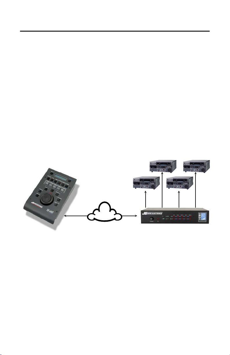
• The ES-450SPE has the ability to work with the JLCooper
eBOX. In this application, the ES-450SPE connects to the
eBOX via an Ethernet connection. The eBOX has four serial
ports that can connect to four VTRs or video server channels as
illustrated in the image below.
Page 5

5
Connecting
Connecting the ES-450SPE is straightforward. Simply connect the
ES-450SPE to a free Ethernet port on your network. The ES450SPE is powered from the power connector on the rear panel.
To configure the ES-450J USB to operate with a specific software
application, refer to the setup documentation for that software
application.
The ES-450SPE uses TCP/IP to communicate with a host device
such as a computer.
Note: Before configuring your JLCooper Ethernet based controller,
you will need a unique IP address for each controller you wish to use.
Your network administrator can supply this to you.
Page 6
6
Configuring the Ethernet Int e rface
1. Install the Lantronix Device Installer v4.x.x.x and Redirector
This is located on the Install CD that came with the product.
Alternately, it can be downloaded from the JLCooper Support
Site at: http://jlcooper.com/pages/downloads.html.
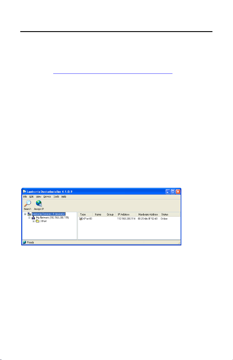
2. Launch Device Installer.
Press Search. The Device Installer application will look for all
the Lantronix products on your network. The factory default of
the Ethernet Interface is 192.168.200.114. If you do not see
this, you will need to change the IP address of your computer
to 192.168.200.nnn (for example, 192.168.200.1) and subnet to
255.255.255.0 so the computer can communicate with the
controller.
Also, if there is more than one Ethernet Interface on the
network, there will be an IP address conflict that will need to
be resolved before using the units.
Page 7
7
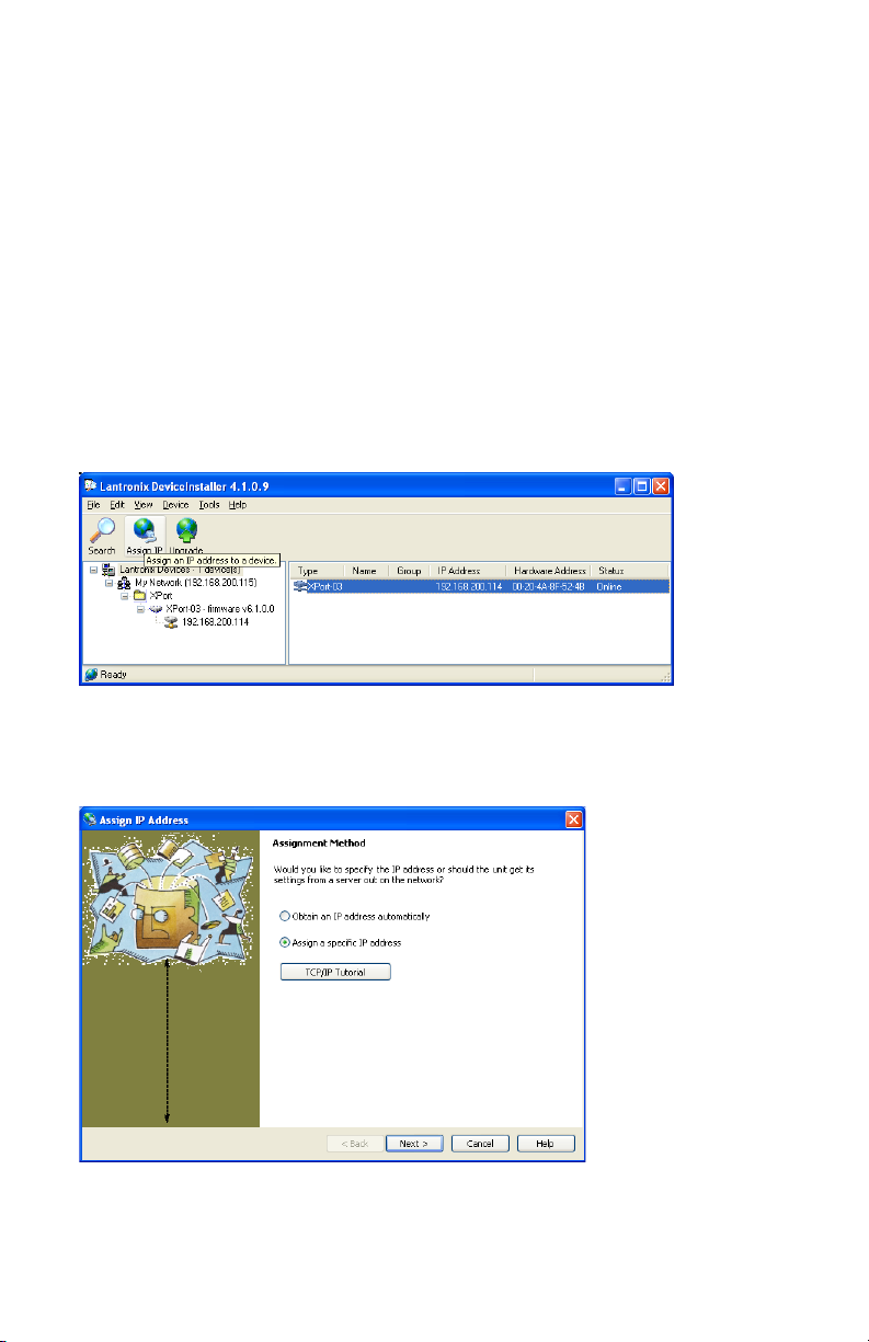
3. Assign an IP Address to the Controller.
The Ethernet interface in your JLCooper Controller is capable
of automatically obtaining an IP address from a DHCP server.
If you have a DHCP server on your network, you will see a
DHCP assigned IP address. Because it is possible for DHCP
assigned IP addresses to expire and get assigned to other
devices, it is strongly recommended that you manually assign a
fixed IP address to the controller.
In the Device Installer window, highlight the item that matches
the Hardware (MAC) Address of your controller.
Click on Assign IP and follow the directions in the following
dialog boxes.
Page 8
8
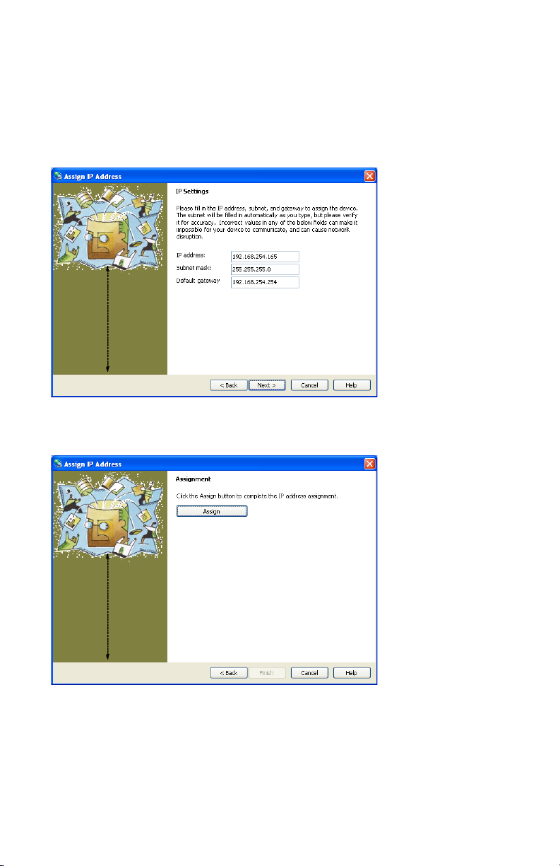
Enter your IP address, Subnet Mask and Default Gateway in the
text boxes. You can assign any valid IP address to the Ethernet
interface. In the example below, the IP address is set to
192.168.254.165, the Subnet Mask is 255.255.255.0 and the
Default Gateway is 192.168.254.254.
Click Assign.
Page 9
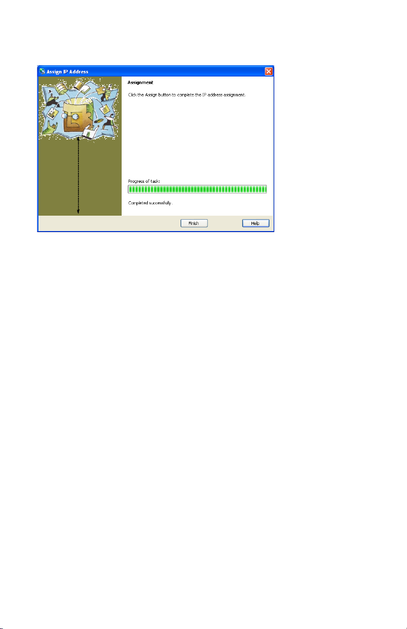
9
Click Finish.
Note: If you change the IP address to an address that is not in your
subnet, you will not be able to connect to the Ethern e t Interface until
you change the IP address of your computer to an address that is in the
subnet range of the Ethernet Interface.
Page 10
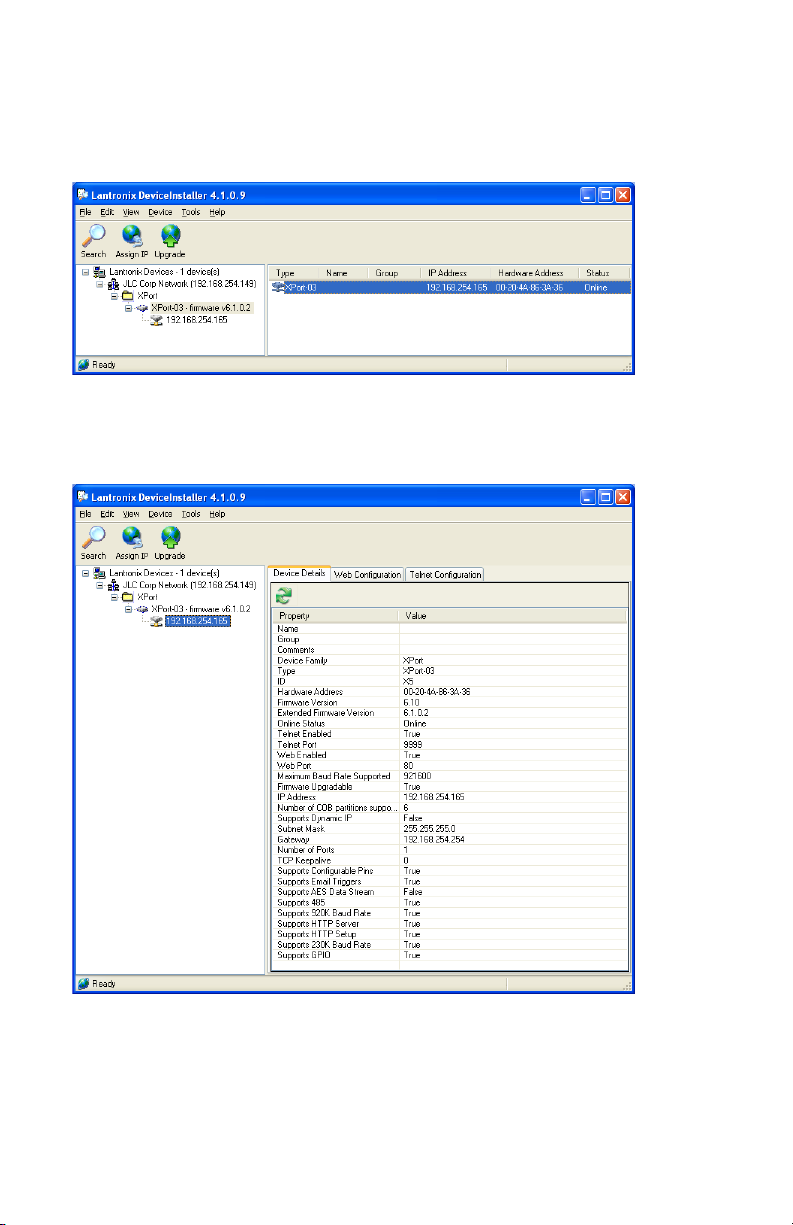
10
4. Configure device settings.
In the Device Installer window, highlight the item that matches
the Hardware (MAC) Address of your controller.
Double click the item and the Device Details window will open as
shown below. Click on the Web Configuration tab.
Page 11

11
A small web browser window will appear. Click the Go button.
A password dialog box will appear. Click OK with a blank User
name and password.
Page 12

12
The web based configuration page will appear. Click on the
Channel 1 Serial Settings link.
Page 13

13
The Serial Settings page will appear. Configure the page as shown
below.
Note: the ES-450SPE in Host Mode uses No Parity.
Click OK.
Page 14

14
If the TCP port or any other TCP/IP settings need to be configured
for your specific environment, click the Channel 1 Connections
link.
Click OK.
Page 15

15
After configuring the Ethernet Interface, click on the Apply
Settings link.
Page 16

16
The Ethernet Interface will store the settings in nonvolatile
memory and restart.
Page 17

17
After the Ethernet Interface restarts, the device will return to the
Home Page. The Ethernet Interface is now ready to use.
Page 18

18
Using the ES-450SPE with an eBOX
Serial
Ethernet
192.168.200.114
Port 10001
192.168.200.115
Port 23456
Serial
Serial
Serial
The ES-450SPE has the ability to connect to the eBOX over an
Ethernet connection and control up to four devices.
In the following example, we will use the following settings to
configure an ES-450SPE and eBOX to communicate.
Port
Port
1
Port
2
3
Port
4
Page 19

19
Configuring the ES-450SPE
To configure the ES-450SPE, simply use the configuration web
page. The default address of the configuration web page is:
192.168.200.114
Note: you may have to change the network settings of your computer
(specifically the IP Address) to match the subnet of the ES-450.
Contact your network administrator for assistance.
You will see a log in screen similar to the one shown below.
Click on the OK button.
Page 20

20
After clicking OK, the following webpage will appear. If it does
not, simply click on the Network item on the left side of the page.
Verify that the Use the following IP configuration option is
selected.
In the IP Address box, enter the desired IP Address of the ES-450.
In the Subnet Mask box, enter the necessary Subnet Mask of the
ES-450.
If the ES-450 will communicate through a router or gateway, enter
the IP Address of the gateway in the Default Gateway box.
Page 21

21
Click OK.
Next, click on the Serial Settings item on the left side of the page.
Verify that the parameters are configured as shown.
Note: the ES-450SPE in eBOX Mode uses No Parity.
Click OK.
Page 22

22
Next, click on the Connection item on the left side of the page.
Verify that the parameters are configured as shown.
Page 23

23
The parameters in Endpoint Configuration section will need to be
Ethernet
192.168.200.114
Port 10001
192.168.200.115
Port 23456
configured for your specific network environment.
The Local Port parameter is the TCP port that the ES-450 uses to
communicate with the eBOX. The ES-450 acts as a TCP client so
connections will be established from this port. In this example, we
will use port 10001. You can use any port except ports 1-1024,
9999, 14000-14009, 30704 and 30718.
The Remote Port parameter is the TCP port of the eBOX. You can
use any port except ports 23, 80 and 4141. In this example, we
will use port 23456.
The Remote Host parameter is the IP Address of the eBOX. You
can use any valid IP Address. In this example, we will use IP
Address 192.168.200.115.
Note: If the IP Address is not in the subnet as defined by the subnet
mask, the ES-450 will attempt to use the gateway to establish a
connection with the eBOX.
When the ES-450 is powered up, it will perform the following
steps:
• Open port 10001 (Local Port) to connect to the eBOX.
• Attempt to connect to the eBOX using the Remote Host and
Remote Port.
Page 24

24
Configuring the eBOX
Dip Swit ch
1 2 3 4 5 6 7 8 Down
Down
Down
Down
Down
Up
Down
Down
Now that the ES-450 is configured, the eBOX must be configured.
In this application, the eBOX will be configured as a TCP server.
In other words, the eBOX will passively sit on the network waiting
for another device to connect to it. In this case, it will be the ES-
450.Before the ES-450 can successfully communicate with the
eBOX, the eBOX must be configured with appropriate parameters.
To configure the eBOX, download and install the eBOX
Configuration Utility from the JLCooper Support website.
http://www.jlcooper.com/pages/downloads.html
Set the eBOX to a known IP Address such as 192.168.254.102 by
setting the rear panel DIP switches as detailed in the chart below:
Launch the application. You will see the following screen.
Page 25

25
Change the following parameters highlighted below in the eBOX
Settings section:
The IP Address parameter is the IP Address of the eBOX. You can
use any valid IP Address. In this example, we will use IP Address
192.168.200.115.
The Subnet Mask parameter is the Subnet Mask of the eBOX. If
the remote device (in this case, the ES-450) is not in the same
subnet as the eBOX, the eBOX will communicate through the
gateway.
The Gateway parameter is the IP Address of the gateway that the
eBOX uses when the remote device (in this case, the ES-450) is
not in the same subnet as the eBOX.
The TCP Port parameter is the TCP port that the eBOX listens on
for a connection from the remote device (in this case, the ES-450).
You can use any port except ports 23, 80 and 4141. In this
example, we will use port 23456.
Page 26

26
To save the settings, click on the Send to eBOX button.
Dip Swit ch
1 2 3 4 5 6 7 8 Up
Up
Up
Down
Down
Up
Down
Down
To have the settings take effect:
1. Power the eBOX off.
2. Set the eBOX to use the user programmable IP Address by
setting the rear panel DIP switches as detailed in the chart
below:
3. Power the eBOX on.
You can verify the settings by entering the new IP address of the
eBOX and clicking on the Get from eBOX button.
The parameters in the eBOX Settings section should match the
settings you previously entered.
Page 27

27
Using the ES-450 with the eBOX
Because the ES-450SPE has more functions compared to the
normal ES-450, the EJECT button is now used modifier button.
That is, pressing it allows the operator to modify the operational
characteristics of the ES-450SPE.
Configuring the mode of operation
The ES-450SPE has three modes of operation.
• Host Mode
In Host Mode, the unit acts as a computer peripheral and
communicates using the Host Mode protocol. This is selected
by removing the jumper internal to the unit.
• EBOX Mode
In eBOX Mode, the unit communicates with the eBOX using
the eBOX protocol. The internal jumper must be installed to
access this mode. This mode can be selected by pressing
EJECT + STOP until the display shows eBOX Mode.
• Doremi Mode
In Doremi Mode, the unit communicates with a Doremi video
server using the Doremi protocol. The internal jumper must be
installed to access this mode. This mode can be selected by
pressing EJECT + STOP until the display shows Doremi
Mode.
Note: Doremi Mode is not fully imp le m e nted at this time.
Page 28

28
Using eBOX Mode
As previously mentioned, the ES-450 can control up to 4 devices.
These devices can be selected by using the EJECT and GOTO
buttons.
Routing commands to the eBOX Serial Ports
Pressing EJECT with a numbered button allows you to enable or
disable the transmission of commands from the ES-450 to specific
serial ports on the eBOX.
• EJECT + 1 (REC/SHIFT)
Enables or disables the transmission of commands to Port 1 on
the eBOX. This is indicated by the LED above the 1 button.
• EJECT + 2 (ASM)
Enables or disables the transmission of commands to Port 2 on
the eBOX. This is indicated by the LED above the 2 button.
• EJECT + 3 (INS)
Enables or disables the transmission of commands to Port 3 on
the eBOX. This is indicated by the LED above the 3 button.
• EJECT + 4 (V)
Enables or disables the transmission of commands to Port 4 on
the eBOX. This is indicated by the LED above the 4 button.
Page 29

29
Routing responses from the eBOX Serial Ports
Pressing EJECT + GOTO with a numbered button allows you to
enable or disable the reception of responses such as timecode and
status from specific serial ports on the eBOX to the ES-450. This
is also known as Tally.
• EJECT + GOTO + 1 (REC/SHIFT)
Enables or disables the reception of responses from Port 1 on
the eBOX. This is indicated by the LED above the 1 button.
• EJECT + GOTO + 2 (ASM)
Enables or disables the reception of responses from Port 2 on
the eBOX. This is indicated by the LED above the 2 button.
• EJECT + GOTO + 3 (INS)
Enables or disables the reception of responses from Port 3 on
the eBOX. This is indicated by the LED above the 3 button.
• EJECT + GOTO + 4 (V)
Enables or disables the reception of responses from Port 4 on
the eBOX. This is indicated by the LED above the 4 button.
Note: Only one serial port on the eBOX can be selected for the
reception of responses or Tally.
Page 30

30
Declaration of Conformity
JLCooper Electronics declares that the product named below conforms to:
Low Voltage Directive (LVD) 2006/95/EC
(Superceded LVD73/23/EEC) on 16th January 2006.
Low Voltage Directive (LVD) 73/23/EEC
(Directive 73/23/EC has recently been the subject of a codification,
requiring a new number)
ES-450SPE
Warning: The installer is responsible for protection against personal contact
with all live connections to power supplies, which contain hazardous voltages.
Company Address:
142 Arena Street
El Segundo, CA, 90245 U.S.A.
Product Name: ES-450SPE
Product Type: Remote Control Panel
Model Number: ES-450SPE
Date of Issue: 16 September 2009
Authorized by:
Title of Authority: Quality Assurance
Declaration Reference: CE/EEC2007TLL
Page 31

31
RoHS Statement of Compli a nc e
June 28, 2006
Re: ES-450SPE
This is a declaration that the items described (herein as RoHS “Class 1”) do not
contain one or more than one:
RoHS restricted substances above the homogeneous material concentration limit
(Threshold Level) per the EU/RoHS directive effective July 1, 2006 and
amending document(s).
JLCooper Electronics products will meet MIL-I 45208. The Company is
currently implementing procedures for ISO 9000:2000, after which feasibility
research will begin for ISO 14000 considerations.
RoHS Class 1 OEM Products:
Hazardous Substance Allowed PPM Level
Cadmium (Cd) 100ppm (0.01%)
Lead (Pb) 1000ppm (0.1%)
Mercury (Hg) 1000ppm (0.1%)
Hexavalent C hr o mi um (CrVI) 1000ppm (0.1%)
Polybrominated Biphenyl's (PBB's) 1000ppm (0.1%)
Polybrominated Diphenyl Ethers (PBDE's) 1000ppm (0.1%)
Supplier evidence of compliance on file meets or exceeds trace ability
requirements of ISO 9000:2000. Where feasible, JL Cooper seeks suppliers with
ISO 9000:2000 Quality and ISO 14000 Environmental Certification.
Sincerely,
Thomas L. Lo wr y
Quality Assurance Department
Page 32

32
JLCooper Electronics Lim ited Factory Warranty
JLCooper Electronics ("JLCooper") warrants this product to be free of defects in
materials or workmanship for a period of 12 months from the date of purchase. This
warranty is non-transferable and the benefits apply only to the original owner. Proof of
purchase in the form of an itemized sales receipt is requ ired for warranty coverage. To
receive service under this warranty, customers in the United States should contact the
JLCooper factory at (310) 322-9990 and talk to a service technician. If necessary, a
Return Authoriz ation number may be issued. For our customers outside the United States,
it is recommended that you first contact your Dealer or Distrib utor, since they may offer
their own service or support policy. If local support is not obtainable, please send a FAX
to JLCooper's Service Department at +1 310 335 0110 with a detailed descrip tion of the
service required. Upon issuance of return authorization, the product should be packed in
the original shipping materials and shipped prepaid and insured to: Service Department,
JLCooper Electronics, 142 Arena Street, El Segundo, CA 90245. Please include the
following: copy of the sales receipt, your name and address (no P.O. Boxes, please), a
brief description of the problem, and any other related items discussed with the service
department and con sid ered necessar y to evalu ate th e p ro du ct or effect a repai r. The return
authorization number must be clearly written on the outside of the package. JLCooper
will, at its option, without charge for parts or labor, either repair or replace the defective
part(s) or unit. Shipping costs, duties, customs, brokerage and other fees to and from
JLCooper are not covered by this warranty. JLCooper's normal repair turn around time at
the factory is approximately 10 business days from receipt of product to shipping. Your
actual turn around time will include return shipping. Actual turn around time will vary
depending upon many factors including the repeatability of the customer's reported
complaint, the availability of parts required for repair, the availability of related products
needed to evaluate the p roduct if necessary. Priority services are available at addi tional
cost. These should be discussed with the service representative at the time the return
authorization is issued. This warranty provides only the benefits specified and does not
cover damage, defects or repairs needed as result of acts beyond the control of JLCooper
including but not limited to: abuse, damage by accident or negligence, damage from
using incorrect power supply, modification, alteration, improper or abnormal use,
unauthorized servicing, tampering, ingress of foreign matter or failure to operate in
accordance with the procedures outlined in the owner's manual; nor for natural or manmade events such as, but not limited to flooding, lightning, tornadoes, earthquake, fire,
civil unrest, war, terrorism, etc.
THE DURATION OF ANY OTHER WARRANTIES, WHETHER IMPLIED OR
EXPRESS, INCLUDING BUT NOT LIMITED TO THE IMPLIED WARRANTY OF
MERCHANTABILITY, IS LIMITED TO THE DURATION OF THE EXPRESS
WARRANTY HEREIN. JLCOOPER HEREBY EXCLUDES INCIDENTAL AND
CONSEQUENTIAL DAMAGES, INCLUDING BUT NOT LIMITED TO: LOSS OF
TIME, INCONVENIENCE, DELAY IN PERFORMANCE OF THIS WARRANTY, THE
LOSS OF USE OF THE PRODUCT OR COMMERCIAL LOSS, AND FOR BREACH
OF ANY EXPRESS OR IMPLIED WARRANTY OF MERCHANTABILITY
APPLICABLE TO THIS PRODUCT. JLCOOPER SHALL NOT BE LIABLE FOR
DAMAGES OR LOSS RESULTING FROM THE NEGLIGENT OR INTENTIONAL
ACTS OF THE SHIPPER OR HIS CONTRACT AFFILIATES. THIS WARRANTY
SHALL BE GOVERENED BY THE LAWS OF THE STATE OF CALIFORNIA.
 Loading...