

Page 1
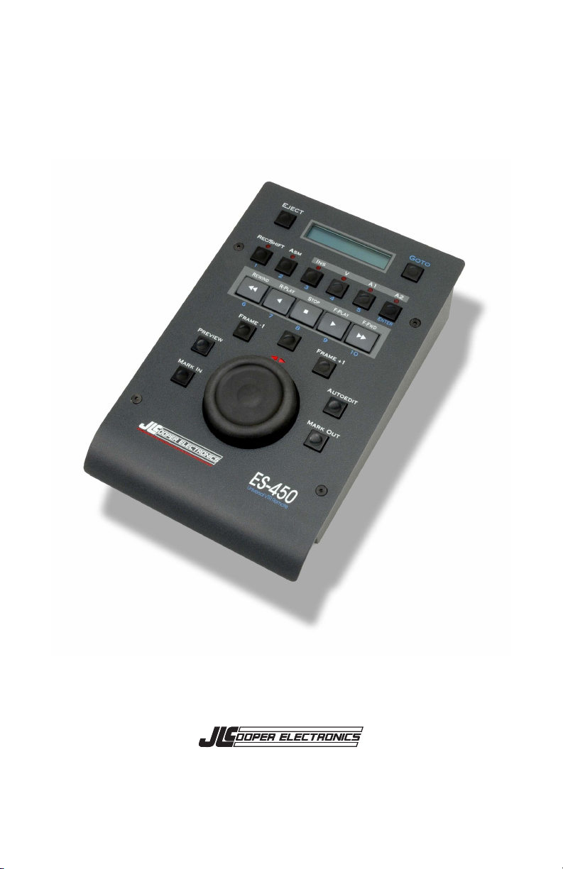
ES-450SP
9-Pin Machine Controller
Users Manual
Page 2

ES-450, ES-450SP and ES-450SP are trademarks of JLCooper Electronics. All
other brand names are the property of their respective owners.
ES-450SP User’s Manual, Third Edition
Part Number 932100
2007 JLCooper Electronics,
142 Arena Street, El Segundo, CA 90245 USA
+1 (310) 322 9990
2
Page 3

Table of Contents
Description..................................................................................... 4
Setting up the ES-450SP............................................................... 5
Controlling a Machine................................................................ 5
Using with a Host Computer....................................................... 5
Configuration ................................................................................ 6
Step Mode.................................................................................... 6
Frame Rate.................................................................................. 6
Track Arming Mode .................................................................... 7
Timecode Select .......................................................................... 8
CTL Timecode Reset ................................................................... 8
Controls.......................................................................................... 9
Jog/Shuttle Wheel........................................................................ 9
Transport Controls ..................................................................... 9
Track Arming ............................................................................ 10
Editing Controls........................................................................ 10
Timecode Window..................................................................... 12
Locate Functions....................................................................... 13
Direct Numeric Entry................................................................ 13
Technical Reference.................................................................... 15
Electrical Interface ................................................................... 15
Command Reference ................................................................. 15
Care and Service....................................................................... 16
JLCooper Electronics Limited Factory Warranty .................. 17
3
Page 4

Description
The ES-450SP is a self-contained machine controller for
professional and semi-professional VTRs, audio decks and
computer based editing systems that support the industry standard
Sony 9-pin protocol. This is also known as Sony “P2” or RS-422
protocol.
ES-450SP features include:
• Timecode display
• Sony-type Jog/Shuttle wheel
• Transport control
• Frame Bump forward and reverse
• Seven Locate points
• Remote Track arming
• Direct timecode entry
• Support for 24/25/29.97/30 frames per second
• Support for Drop and non-Drop timecode
• Support for VITC/LTC and CTL Timecode
4
Page 5

Setting up the ES-450SP
The ES-450SP can operate in either of two modes: as a stand-alone
master controller for VTRs and decks that respond to the Sony 9pin protocol or, as a slave device meant to be attached to a host
that directly supports the ES-450SP. See your system
documentation for details. As shipped from the factory, the ES450SP is normally configured as a deck controller.
Controlling a Machine
As a deck controller the ES-450SP requires little in the way of
setup to use it with a VTR or audio deck.
1. Connect the 9-pin D-sub connector from the
rear of the ES-450SP to your machine or computer.
2. Connect the supplied power supply to the end
of the cable attached to the ES-450SP
3. Select Frame Rate by pressing SHIFT + EJECT
Your machine must be set for remote operation. Please consult
your Operators Manual for details.
Using with a Host Computer
Using the ES-450SP with a host computer requires the unit to be
changed to slave mode. To do so, you will need the following
tools: a 5/64" hex wrench, and a small flat-blade screwdriver.
1. Remove the four Allen screws from the front panel.
2. Carefully remove the front panel from the bottom chassis.
3. On the small circuit board, remove the 8-pin IC, which is
inserted into U3 “To Mach.” socket, and move it to the "To
Host" socket. Make sure orientation is preserved.
4. Remove the jumper JB1.
(In case the unit might be changed back in the future, you
can re-plug in the jumper to only on pin of JB1.)
5. Reassemble the front panel to the bottom chassis.
5
Page 6

Configuration
Before using the ES-450SP, we recommend setting it up for the
various ways you may need to use it in.
Step Mode
This setting is used to set how the ES-450SP performs the
Frame+1 and Frame-1 operations. This determines how the ES450SP behaves at whole second boundaries. This is toggled by
pressing SHIFT+STOP. The two options are:
• Cue Up Step Mode (Default)
This configures the ES-450SP to send a Cue Up with Data
command when the Frame+1 (or Frame-1) button is
pressed. This essentially commands the machine to locate
to the next frame (or previous frame).
• SloMo Step Mode
This configures the ES-450SP to send a Shuttle command
when the Frame+1 (or Frame-1) button is pressed. This
essentially commands the machine to shuttle forward (or
reverse) until the next frame (or previous frame) is
encountered.
Frame Rate
This setting is used to set the frame rate used in Frame+1 and
Frame-1 calculations. This is done by pressing SHIFT + EJECT.
This will switch between the following frame rates:
• 24 (Film)
• 25 (PAL)
• 30 (NTSC)
6
Page 7

Track Arming Mode
This determines how the audio track arming is handled. This is
toggled by pressing SHIFT+R-PLAY. The options are:
• Type 1 (Default)
Older decks with 2 analog tracks.
A1 = Analog Audio 1 (This is sometimes interpreted as
Digital Audio 1 in some decks)
A2 = Analog Audio 2 (This is sometimes interpreted as
Digital Audio 2 in some decks)
Shift + A1 = Analog Audio 3 (TC in some decks)
Shift + A2 = Analog Audio 4 (Sync in some decks)
• Type 2
Sends a 2 byte track arm message with the A1 & A2 bits
copied from the D1 & D2 bits. Tally back uses byte 5 of
the Status message.
A1 = Analog Audio 1 and Digital Audio 1
A2 = Analog Audio 2 and Digital Audio 2
Shift + A1 = Digital Audio 3
Shift + A2 = Digital Audio 4
• Type 3
Same as Type 2, except Tally back uses the Edit Preset
Sense message.
A1 = Analog Audio 1 and Digital Audio 1
A2 = Analog Audio 2 and Digital Audio 2
Shift + A1 = Digital Audio 3
Shift + A2 = Digital Audio 4
• Type 4
Same as Type 2, except the A1 & A2 bits are set to zero.
A1 = Digital Audio 1
A2 = Digital Audio 2
Shift + A1 = Digital Audio 3
Shift + A2 = Digital Audio 4
7
Page 8

Timecode Select
This set the timecode that the ES-450SP displays in its timecode
window. This is toggled by pressing SHIFT+FFWD. The options
are:
• VITC/LTC Timecode
• CTL Timecode
CTL Timecode Reset
The ES-450 can reset the CTL timecode. This is done by pressing
SHIFT+REWIND.
8
Page 9

Controls
The ES-450SP was laid out in an ergonomic manner. It was
designed to be used by left- or right-handed operators. With the
operators hand resting on the JOG/SHUTTLE WHEEL, the most
commonly used transport buttons are in easy reach.
Jog/Shuttle Wheel
The JOG/SHUTTLE WHEEL has two modes. The mode can be
changed by simply pressing the wheel.
In the Shuttle Mode, the wheel has a detent in the center and at the
two extreme positions. In the center position, The ES-450SP
places the machine into Shuttle Still or Pause mode. As the wheel
is turned clockwise, the machine will start shuttling forward.
Conversely, as the wheel turned counterclockwise, the machine
will start shuttling in the reverse direction. The two arrow LEDs
indicate the direction the tape is moving. When both arrow LEDs
are illuminated, the machine is in Shuttle Still or Pause mode.
Below are typical shuttle speeds from the center detent to the
extreme ends of rotation:
Still 1/8x ¼x ½x ¾x 1x 1¼x 1½x 2x 3x 4x 5x 6x 10x 13x 16x
In the Jog Mode, the wheel turns freely without any detents or
stops. Turning the wheel clockwise moves the tape forward.
While turning the wheel counterclockwise moves the tape in the
reverse direction. The two arrow LEDs indicate the direction the
tape is moving. When the Jog wheel is not being turned, both
arrow LEDs will be off indicating that the machine is in Jog Still
or Pause mode.
Transport Controls
The Transport Controls are positioned above the JOG/SHUTTLE
WHEEL. These functions include: STOP, PLAY, REVERSE
9
Page 10

PLAY, FAST FORWARD and REWIND. Additionally, there is
an EJECT button in the upper left hand corner of the front panel.
Typically, pressing the STOP button places the machine into Still
or Pause mode so the operator can view the image on tape.
Pressing FAST FORWARD and REWIND place the machine into
Shuttle Forward and Shuttle Reverse respectively. These functions
may be implemented differently in your machine or editing
software.
Track Arming
Above the Transport Controls are the Track Arming buttons, which
select tracks to be overwritten when the machine is placed in
Record. Pressing the ASM button will place the machine in to
Assemble mode where the video and audio tracks are written. To
insert new material over existing material, the Insert mode is used.
To initiate Insert mode, press the INS button and any tracks you
wish to record.
LEDs above the Track Arming buttons indicate the tracks that are
armed or being recorded on.
Record is initiated by pressing REC/SHIFT and F-PLAY.
Editing Controls
Located around the JOG/SHUTTLE WHEEL are the Editing
Controls. At the top center just above the JOG/SHUTTLE
WHEEL is the SHUTTLE SELECT button. The SHUTTLE
SELECT button allows the machine to return to a shuttle operation
after it has been interrupted by a Stop, Frame+1, Frame-1 or Goto
command. The direction arrows indicate the direction of the
pending shuttle. In Jog mode, this button has no effect.
On either side of the SHUTTLE SELECT button are the
FRAME+1 and FRAME-1 buttons. Pressing either of these
buttons will move or bump the tape forward or backwards one
frame. This is performed by using the timecode returned to the
10
Page 11

ES-450SP by the machine. The frame rate must be set for this
function to operate properly. To set the frame rate, press SHIFT +
EJECT. This setting is stored in nonvolatile memory.
There are two ways to perform this based on the ballistics of the
controlled deck: “Cue Up” mode and “Slo Mo” mode. These can
be selected by pressing SHIFT + STOP. This setting is also stored
in nonvolatile memory.
The default method is “Cue Up” mode. In this mode, the ES450SP sends a Locate command that is incremented or
decremented by one frame. This works well for hard disk based
systems and newer decks.
The alternate method is “Slo Mo” mode. In this mode, the ES450SP sends a shuttle slow command in the appropriate direction.
The ES-450SP sends a STILL command when the machine
responds with timecode that is incremented or decremented by one
frame. This is better suited for older decks that have trouble with
locating a short distance.
Note:
If the machine does not use the timecode it sends out of the
remote connector as the locate reference, the machine will
locate to the wrong point. An example of this would be a
machine that sends VITC timecode to the remote, but uses
LTC to locate.
MARK IN and MARK OUT buttons send Mark In and Mark Out
commands to the machine. These are used to set points used in
Preview and Autoedit operations.
The PREVIEW button sends a Preview command to the machine.
This allows the operator to preview an edit. Typically, this
command causes the machine to perform the following actions:
1. Locate to the Mark In point minus the pre roll
2. Enter Play mode
11
Page 12

3. Switch to input monitor at the Mark In point
4. Revert to tape monitor at the Mark Out point
5. Stop the tape at the Mark Out point plus the post roll
The AUTOEDIT button sends an Auto Edit command. This allows
the operator to perform an edit with frame accuracy. Typically,
this command causes the machine to perform the following
actions:
1. Locate to the Mark In point minus the preroll
2. Enter Record Ready mode
3. Switch to Record mode at the Mark In point
4. Revert to Record Ready mode at the Mark Out point
5. Stop the tape at the Mark Out point plus the postroll
Timecode Window
The Timecode Window displays the timecode that the machine
sends via the 9-pin interface. This is usually the longitudinal
timecode of the media. Some machines will send timecode
derived from VITC, a dedicated timecode track or the control
track. The timecode is displayed in hours:minutes:seconds:frames
format. Drop frame timecode is indicated by a small dot or period
between “LTC” and the hours field.
TC= 01:25:36:12
Non-Drop frame timecode
TC=
.01:25:36:12
Drop frame timecode
The Timecode Window can also display the control track counter
or CTL timecode. This is toggled by pressing SHIFT+FFWD.
The ES-450 can reset the CTL timecode. This is done by pressing
SHIFT+REWIND.
CT= 01:25:36:12
CTL timecode
12
Page 13

Locate Functions
The ES-450SP can store up to seven locate points internally.
These locate points are stored as long as the unit is powered.
The locate buttons are secondary functions of the Editing Controls.
The locate buttons are identified in the following table:
Mark In Locate 1
Preview Locate 2
Frame-1 Locate 3
Shuttle Select Locate 4
Frame+1 Locate 5
Autoedit Locate 6
Mark Out Locate 7
Locate points are set by pressing and holding REC/SHIFT then the
desired locate button. Locate points are recalled by pressing
GOTO then the desired locate button. Locate points are stored in
memory as long as the unit is powered.
Direct Numeric Entry
The ES-450SP can also command the machine to locate to an
arbitrary timecode position. This is initiated by pressing the
GOTO button. The display will show:
GoTo : : :
Using the Transport and Track Arming Buttons, key in the desired
timecode then press ENTER. The machine will immediately go to
the entered timecode.
13
Page 14

Note: The ES-450SP does not check for the validity of the entered
timecode. It merely passes the entered timecode to the deck. This
can cause unpredictable results if an invalid timecode is entered.
This can occur in a few instances:
1. An hour, minute or second value that doesn’t exist.
Example: 00:00:73:00
2. A frame greater than the current frame rate is entered.
Example: In 24fps mode, entering 00:00:00:29
3. In Drop Frame operation, a dropped frame is entered.
Example: 00:12:00:00.
14
Page 15

Technical Reference
Electrical Interface
The ES-450SP uses the EIA RS-422A protocol over a 9 pin D-Sub
connector. The pinout is listed in the table below:
1 Ground
2 Receive A
3 Transmit B
4 Ground (Transmit)
5 not used
6 Ground (Receive)
7 Receive B
8 Transmit A
9 Ground
The ES-450SP sends data at 38.4 kbits/sec. The data format is 1
start bit, 8 data bits, 1 stop bit and 1 parity bit. The parity is odd.
That is, the sum of the data bits and the parity bit is an odd
number.
D7 + D6 + D5 + D4 + D3 + D2 + D1 + D0 + P = odd number
Command Reference
When the ES-450SP is powered up, the unit constantly queries the
deck for timecode and status:
15
Page 16

Troubleshooting
If for some reason the ES-450SP does not give you the expected
results, take a moment to do some investigating. The most
important concept is that you have your ES-450SP connected
properly as outlined in Setting up the ES-450SP. Take a minute to
double check this setup.
Double check with the manufacturer of the deck you are
controlling to see if an external controller is supported. As long as
your cable connections are setup properly, everything should be
working.
Make sure your machine is set to "Remote" and not "Local"
control. This will insure that your ES-450SP is communicating
with your machine.
Care and Service
If properly cared for, your ES-450SP should provide years of
troublefree performance. Avoid dropping the ES-450SP or banging
hard on the controls.
Clean with a soft, damp cloth. Do not allow liquids to get inside
the unit.
There are no user-serviceable parts in the ES-450SP. Please refer
to the JLCooper Electronics Limited Factory Warranty for detailed
warranty and service information.
16
Page 17

JLCooper Electronics Limited Factory Warranty
JLCooper Electronics ("JLCooper") warrants this product to be free of defects in
materials or workmanship for a period of 12 months from the date of purchase. This
warranty is non-transferable and the benefits apply to the original owner. Proof of
purchase in the form of an itemized sales receipt is required for warranty coverage. To
receive service under this warranty, customers in the United States should contact the
JLCooper factory at (310) 322-9990 and talk to a service technician. If necessary, a
Return Authorization number may be issued. For our customers outside the United States,
it is recommended that you first contact your Dealer or Distributor, since they may offer
their own service or support policy. If local support is not obtainable, please send a FAX
to JLCooper's Service Department at +1 310 335 0110 with a detailed description of the
service required. Upon issuance of return authorization, the product should be properly
packed and shipped to: Service Department, JLCooper Electronics, 142 Arena Street, El
Segundo, CA 90245. Please include the following: copy of the sales receipt, your name
and address (no P.O. Boxes, please), a brief description of the problem, and any other
related items discussed with the service department and considered necessary to evaluate
the product or effect a repair. The return authorization number must be clearly written on
the outside of the package. JLCooper will at its option, without charge for parts or labor,
either repair or replace the defective part(s). Shipping costs are not covered by this
warranty. JLCooper's normal repair turn around time at the factory is approximately 15
business days from receipt of product to shipping. Your actual turn around time will
include return shipping. Actual turn around time will vary depending upon many factors
including the repeatability of the customer's reported complaint, the availability of parts
required for repair, the availability of related products needed to evaluate the product if
necessary. Priority services are available at additional cost. These should be discussed
with the service technician at the time the return authorization is issued.This warranty
provides only the benefits specified and does not cover defects or repairs needed as result
of acts beyond the control of JLCooper including but not limited to: abuse, damage by
accident/negligence, modification, alteration, improper use, unauthorized servicing,
tampering, or failure to operate in accordance with the procedures outlined in the owner's
manual; nor for natural or man-made events such as, but not limited to flooding,
lightning, tornadoes, earthquake, fire, civil unrest, war, etc.
THE DURATION OF ANY OTHER WARRANTIES, WHETHER IMPLIED OR
EXPRESS, INCLUDING BUT NOT LIMITED TO THE IMPLIED WARRANTY OF
MERCHANTABILITY, IS LIMITED TO THE DURATION OF THE EXPRESS
WARRANTY HEREIN. JLCOOPER HEREBY EXCLUDES INCIDENTAL AND
CONSEQUENTIAL DAMAGES, INCLUDING BUT NOT LIMITED TO: LOSS OF
TIME, INCONVENIENCE, DELAY IN PERFORMANCE OF THIS WARRANTY,
THE LOSS OF USE OF THE PRODUCT OR COMMERCIAL LOSS, AND FOR
BREACH OF ANY EXPRESS OR IMPLIED WARRANTY OF MERCHANTABILITY APPLICABLE TO THIS PRODUCT. JLCOOPER SHALL NOT BE LIABLE
FOR DAMAGES OR LOSS RESULTING FROM THE NEGLIGENT OR
INTENTIONAL ACTS OF THE SHIPPER OR HIS CONTRACT AFFILIATES. THE
CUSTOMER SHOULD CONTACT THE SHIPPER FOR PROPER CLAIMS
PROCEDURES IN THE EVENT OF DAMAGE OR LOSS RESULTING FROM
SHIPMENT. THIS WARRANTY SHALL BE GOVERENED BY THE LAWS OF THE
STATE OF CALIFORNIA.
17
 Loading...