

Page 1
Eclipse Series
Joiner Kit
Silver Finish and Midnight Finish
Installation Manual
Page 2

Eclipse Series and Eclipse Series Joiner Kit are trademarks of JLCooper
Electronics. All other brand names are the property of their respective owners.
Eclipse Series Joiner Kit Installation Manual,
First Edition (September 21, 2009)
Part Number 932116
2009 JLCooper Electronics, 142 Arena Street, El Segundo, CA 90245 USA
(310) 322-9990 ¬ (310) 335-0110 www.jlcooper.com
2
Page 3

Table of Contents
Introduction................................................................................... 4
Installation..................................................................................... 5
Unpacking................................................................................... 5
Required Tools............................................................................ 5
Assembly Instructions ................................................................. 6
RoHS Statement of Compliance ................................................ 10
Declaration of Conformity ......................................................... 11
JLCooper Electronics Limited Factory Warranty .................. 12
3
Page 4

Introduction
The Eclipse Series Joiner Kit allows you to join two or more
Eclipse style controllers into one seamless unit. The Eclipse Series
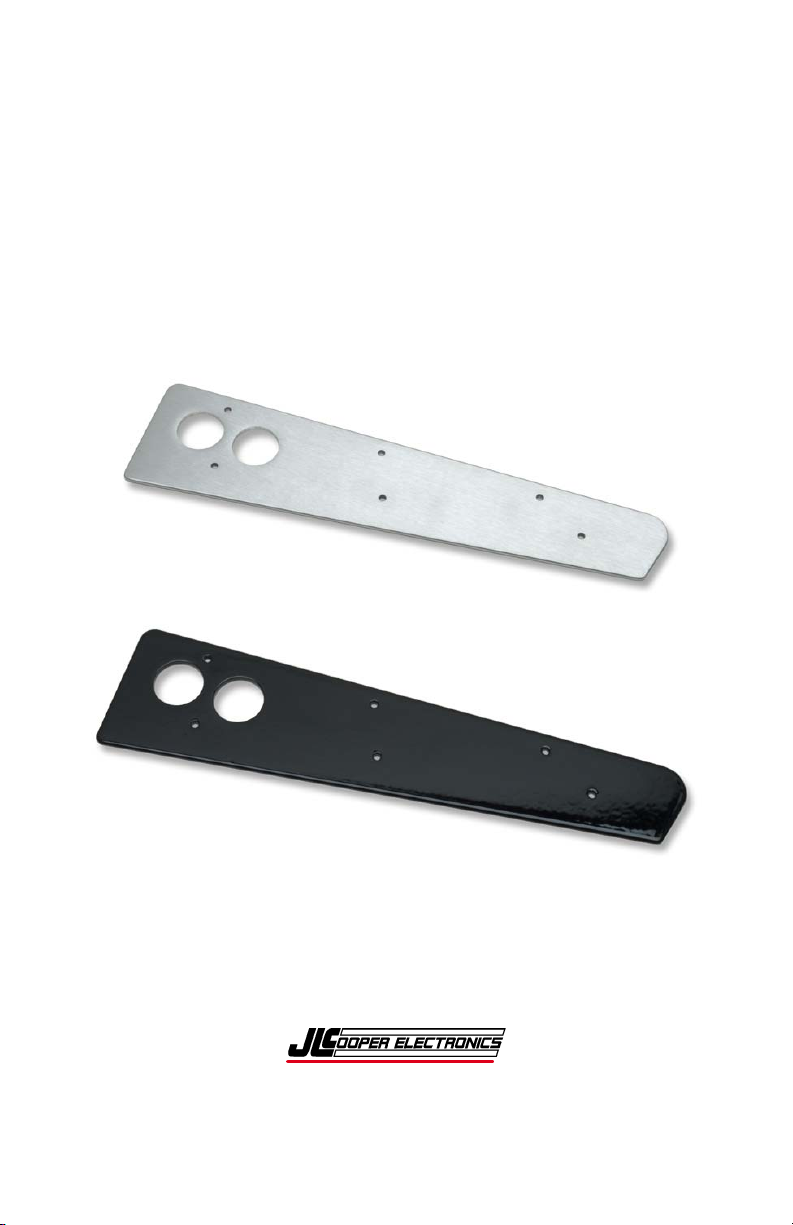
Joiner Kit comes in two different finishes:
• Silver Finish
• Midnight Finish
The Eclipse Series Joiner Kit features two large openings to allow
you to pass the data and, in some cases, the power cables between
the master and expansion units.
4
Page 5

Installation
Unpacking
When you receive your Eclipse Series Joiner Kit, you should
receive the following items:
• 1 Eclipse Joiner Plate (Silver or Midnight finish)
• This Installation Manual
• 6 Screws, 6-32 x ½ inch Phillips Head (JLC P/N 261006)
• 6 Nuts, 6-32 (JLC P/N 282006)
• 1 1/16 inch hex driver (JLC P/N 933014)
• 1 5/64 inch hex driver (JLC P/N 933008)
If you have not already done so, please take a moment to register
your Eclipse products at:
http://www.jlcooper.com
This will allow us to notify you of important updates and changes
to software or features.
Required Tools
To complete the installation of the Eclipse Series Joiner Kit you
will need the following:
• A clean, well lit, ESD protected work surface
with a soft surface
• 1/16 inch hex driver (supplied)
• 5/64 inch hex driver (supplied)
• #1 Philips screwdriver (not supplied)
• #2 Philips screwdriver (not supplied)
• 1/4 inch nut driver (not supplied)
• Container to store hardware during disassembly (optional)
5
Page 6

Assembly Instructions
Note: To avoid scratching or otherwise damaging the
unit, use a clean work surface with a soft rubber surface
when performing the following procedure.
1. Remove all external screws from bottom of both units using a
#1 Philips screwdriver and set aside for reassembly.
2. Remove six external screws (three along each side) from top of
both units, using the supplied 5/64 inch hex driver and set aside
for reassembly.
6
Page 7

3. Carefully separate the top panel from the bottom panel of both
units. Set aside top panels for reassembly.
4. Remove the three screws attaching the side panel to the bottom
panel from the desired side of each unit, using a #2 Philips
screwdriver. Set aside bottom panel.
5. Remove three screws attaching the silver right angle bracket
from both side panels using the 1/16 inch hex driver.
7
Page 8

6. Attach both brackets to joiner metal with smaller screws and
the nuts, so that there is a bracket on each side of the joiner.
Be sure that the threaded holes of the bracket are facing up.
Secure screw and nut with the 1/16 inch hex driver and a 1/4
inch nut driver.
7. Arrange the two bottom panels in the desired configuration.
Place the Eclipse Series Joiner between the two bottom panels.
Align the three mounting holes in the bottom panel so that they
pass through the three mounting holes in the Eclipse Series
Joiner.
8. Attach the two bottom metal pieces to the joiner with three
supplied Philips head screw and nuts. Tighten until secure
using a #2 Philips screwdriver and 1/4 inch nut driver.
9. Replace the top metal for both units. During this time, it may
be possible pass the data and/or power cables between the units
by passing the cables through the two circular holes in the
Eclipse Series Joiner. Consult the documentation of the
specific Eclipse units or contact the JLCooper Service
Department.
8
Page 9

10. Replace and secure all screws on for the top panel with the
5/64 inch hex driver.
11. Replace and secure all screws in the bottom panel with a #1
Philips screwdriver.
9
Page 10

RoHS Statement of Compliance
16 September 2009
Re: Eclipse Series Joiner Kit
This is a declaration that the items described (herein as RoHS “Class 1”) do not
contain one or more than one:
RoHS restricted substances above the homogeneous material concentration limit
(Threshold Level) per the EU/RoHS directive effective July 1, 2006 and
amending document(s).
JLCooper Electronics products will meet MIL-I 45208. The Company is
currently implementing procedures for ISO 9000:2000, after which feasibility
research will begin for ISO 14000 considerations.
RoHS Class 1 OEM Products:
Hazardous Substance Allowed PPM Level
Cadmium (Cd) 100ppm (0.01%)
Lead (Pb) 1000ppm (0.1%)
Mercury (Hg) 1000ppm (0.1%)
Hexavalent Chromium (CrVI) 1000ppm (0.1%)
Polybrominated Biphenyl's (PBB's) 1000ppm (0.1%)
Polybrominated Diphenyl Ethers (PBDE's) 1000ppm (0.1%)
Supplier evidence of compliance on file meets or exceeds trace ability
requirements of ISO 9000:2000. Where feasible, JL Cooper seeks suppliers
with ISO 9000:2000 Quality and ISO 14000 Environmental Certification.
Sincerely,
Thomas L. Lowry
Quality Assurance Department
10
Page 11

Declaration of Conformity
JLCooper Electronics declares that the product named below conforms to:
Low Voltage Directive (LVD) 2006/95/EC
(Superceded LVD73/23/EEC) on 16th January 2006.
Low Voltage Directive (LVD) 73/23/EEC
(Directive 73/23/EC has recently been the subject of a codification,
requiring a new number)
Eclipse Joiner Kit
Warning: The installer is responsible for protection against personal contact
with all live connections to power supplies, which contain hazardous voltages.
Company Address:
142 Arena Street
El Segundo, CA, 90245 U.S.A.
Product Name: Media Command Station
Product Type: Multimedia Controller
Model Number: Eclipse Series Joiner Kit
Date of Issue: 16 September 2009
Authorized by:
Title of Authority: Quality Assurance
Declaration Reference: CE/EEC2007TLL
11
Page 12

JLCooper Electronics Limited Factory Warranty
JLCooper Electronics ("JLCooper") warrants this product to be free of defects in materials or
workmanship for a period of 12 months from the date of purchase. This warranty is nontransferable and the benefits apply only to the original owner. Proof of purchase in the form of
an itemized sales receipt is required for warranty coverage. To receive service under this
warranty, customers in the United States should contact the JLCooper factory at (310) 3229990 and talk to a service technician. If necessary, a Return Authorization number may be
issued. For our customers outside the United States, it is recommended that you first contact
your Dealer or Distributor, since they may offer their own service or support policy. If local
support is not obtainable, please send a FAX to JLCooper's Service Department at +1 310 335
0110 with a detailed description of the service required. Upon issuance of return authorization,
the product should be packed in the original shipping materials and shipped prepaid and
insured to: Service Department, JLCooper Electronics, 142 Arena Street, El Segundo, CA
90245. Please include the following: copy of the sales receipt, your name and address (no P.O.
Boxes, please), a brief description of the problem, and any other related items discussed with
the service department and considered necessary to evaluate the product or effect a repair. The
return authorization number must be clearly written on the outside of the package. JLCooper
will at its option, without charge for parts or labor, either repair or replace the defective part(s)
or unit. Shipping costs are not covered by this warranty. JLCooper's normal repair turn around
time at the factory is approximately 15 business days from receipt of product to shipping. Your
actual turn around time will include return shipping. Actual turn around time will vary
depending upon many factors including the repeatability of the customer's reported complaint,
the availability of parts required for repair, the availability of related products needed to
evaluate the product if necessary. Priority services are available at additional cost. These
should be discussed with the service technician at the time the return authorization is issued.
This warranty provides only the benefits specified and does not cover defects or repairs needed
as result of acts beyond the control of JLCooper including but not limited to: abuse, damage by
accident/negligence, damage from using incorrect power supply, modification, alteration,
improper use, unauthorized servicing, tampering, or failure to operate in accordance with the
procedures outlined in the owner's manual; nor for natural or man-made events such as, but not
limited to flooding, lightning, tornadoes, earthquake, fire, civil unrest, war, terrorism, etc.
THE DURATION OF ANY OTHER WARRANTIES, WHETHER IMPLIED OR EXPRESS,
INCLUDING BUT NOT LIMITED TO THE IMPLIED WARRANTY OF
MERCHANTABILITY, IS LIMITED TO THE DURATION OF THE EXPRESS
WARRANTY HEREIN. JLCOOPER HEREBY EXCLUDES INCIDENTAL AND
CONSEQUENTIAL DAMAGES, INCLUDING BUT NOT LIMITED TO: LOSS OF TIME,
INCONVENIENCE, DELAY IN PERFORMANCE OF THIS WARRANTY, THE LOSS OF
USE OF THE PRODUCT OR COMMERCIAL LOSS, AND FOR BREACH OF ANY
EXPRESS OR IMPLIED WARRANTY OF MERCHANTABILITY APPLICABLE TO THIS PRODUCT. JLCOOPER SHALL NOT BE LIABLE FOR
DAMAGES OR LOSS RESULTING FROM THE NEGLIGENT OR INTENTIONAL ACTS
OF THE SHIPPER OR HIS CONTRACT AFFILIATES. THE CUSTOMER SHOULD
CONTACT THE SHIPPER FOR PROPER CLAIMS PROCEDURES IN THE EVENT OF
DAMAGE OR LOSS RESULTING FROM SHIPMENT. THIS WARRANTY SHALL BE
GOVERENED BY THE LAWS OF THE STATE OF CALIFORNIA.
12
 Loading...