

Page 1
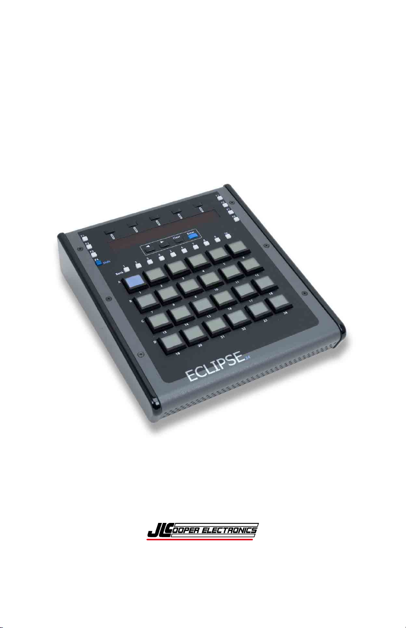
ECLIPSE
2
4
Midnight Finish
Compact Tactile Control Surface
Users Manual
Page 2

Eclipse24 Midnight Finish and Eclipse24 are trademarks of JLCooper
Electronics. All other brand names are the property of their respective owners.
Eclipse 24 User’s Manual, First Edition
Part Number 932120
2011 JLCooper Electronics, 142 Arena Street, El Segundo, CA 90245 USA
(310) 322-9990 ¬ (310) 335-0110 www.jlcooper.com
2
Page 3

Table of Contents
Introduction................................................................................... 4
Installation..................................................................................... 5
Unpacking................................................................................... 5
Setup............................................................................................ 5
Connecting the Eclipse 24 .......................................................... 5
Self Test....................................................................................... 6
Technical Reference...................................................................... 7
Electrical Connections................................................................ 7
Troubleshooting ........................................................................ 11
Care and Service....................................................................... 11
Configuring the Host Application............................................. 11
RoHS Statement of Compliance ................................................ 12
Declaration of Conformity ......................................................... 13
JLCooper Electronics Factory Warranty................................. 14
3
Page 4

Introduction
The Eclipse24 Midnight is a tactile control surface intended for
clip playout systems.
The unit features a 10/100 RJ-45 Ethernet connector and a DC
power jack. The unit can be power from the supplied power
adaptor or powered from 12 volts DC. An LED indicator shows
status of Ethernet activity.
The Eclipse 24 has an expansion slot that allows the addition of the
MCS-Series RS-232 Interface or the MCS-Series RS-422
Interface.
4
Page 5

Installation
Unpacking
When you receive your Eclipse 24 Midnight, you should receive
the following items:
• Eclipse 24 Midnight
• This Users Manual
• Power Supply
• Power Cord
Please take a moment to register your product at:
http://www.jlcooper.com
This will allow us to notify you of important updates and changes
to software or features.
Setup
The compact design of the Eclipse 24 makes it easy to locate
wherever you need it. The Eclipse 24 must be setup up in a
location that does not experience vibration, excessive humidity,
dust or temperature extremes.
Connecting the Eclipse 24
The Eclipse24 can connect to the host directly using the building
Ethernet Interface or using an interface card installed in the
expansion slot. This can be an RS-422 or RS-232 Interface card.
Refer to the next section for specific instructions on how to
connect the Eclipse24 to your host computer.
The Eclipse 24 typically uses the MCS-Ethernet Interface which
connects to any 10baseT or 100baseTX Ethernet network.
1. Connect the Eclipse 24 to the Ethernet network
2. Connect the included power supply to the Eclipse 24.
5
Page 6

Self Test
The Eclipse24 has a self test mode which aids in troubleshooting
the controller. The self mode is accessed by pressing and holding
Page 1 during power up.
6
Page 7

Technical Reference
Electrical Connections
The Eclipse24 can have a variety of interface options. Among
these are:
• Built In Ethernet Interface
• MCS-3000 Series RS-422 Card #920465
• MCS-3000 Series RS-232 Card #920466
Built In Ethernet Interface
The Ethernet Interface is intended for operation with a host
computer. It provides the advantages of a standard interface, long
cable runs, use over private/public/wired/wireless networks, the
ability of being shared among computers and the ability to work
with any platform that supports TCP/IP.
To use the Ethernet Interface, the software application MUST be
written to specifically support the Ethernet Interface. Consult your
software’s users documentation for details on how to configure the
software.
To configure the Eclipse24 Ethernet settings, an Ethernet Interface
card must be in slot 1. You can verify this by visually checking
slot 1 for the presence of an Ethernet card.
To set the IP address, press Page4 + Page6 to access the
configuration page. Follow the display prompts to configure the
Ethernet settings.
Use the Bank buttons to enter the numeric buttons. Use Bank 10
for zero.
The Enter and Clear buttons enter or clear the value respectively.
Note: You must power cycle the Eclipse24 for the Ethernet settings to take effect.
7
Page 8

MCS-3000 Series RS-422 Interface Card
The RS-422 Interface is intended for operation with a VTR,
controller or a host computer. It provides the advantages of RS422, which allows for long cable runs. With low loss, low
capacitance cable, the RS-422 Interface Card can accommodate
cable runs up to 1km.
The RS-422 Interface has a female D-Sub connector. The
interface can be configured to connect to either a deck or a host.
Five jumpers on the interface card configure the pinout. All five
jumpers must be places in either the “To Computer” or “To
Machine” position. The port is configured to communicate at
38400 bits/sec, 1 start bit, 8 data bits, 1 stop bit and odd parity.
MCS-RS422 Interface Pinout
Setting on Card
“To Computer” “To Machine”
1
2
3
4
5
6
7
8
9
Note: These signals are at the RS-422 Interface card.
Ground Ground
Transmit A Receive A
Receive B Transmit B
Ground Ground
not used not used
Ground Ground
Transmit B Receive B
Receive A Transmit A
Ground Ground
MCS-3000 Series RS-232 Interface Card
The RS-232 Interface is intended for operation with a host
computer. It provides the advantages of a standard interface,
which is found on many computers.
8
Page 9
The RS-232 Interface has a male D-Sub connector. The port is
configured to communicate at 1 start bit, 8 data bits, 1 stop bit and
odd parity. Five jumpers allow the port speed to be set for 38400,
19200, 9600, 4800 and 2400 bits/sec to accommodate various
situations.
MCS-RS232 Interface Pinout
1
2
3
5
6
8
Note: These signals are at the RS-232 Interface card
* These pins are not used by the card and are
connected together for ports that require handshake.
DCD*
Transmit
Receive
Ground
DSR*
CTS*
9
Page 10

Power
The Eclipse24 requires a 12 volt DC supply capable of delivering
at least 3 amps. The unit comes with a p r supply approp
owe riate
for the country in which the unit was sold. If you need a power
supply specific to your location, please contact your local
distributor or JLCooper Electronics.
Location JLCooper Part Number
North America TBD
Outside
North America
Table 2: JLCooper approved Power Supplies
Warning: Using a power supply other than the units specified in the
above table can result in damage to the Eclipse24 and/or other
equipment which is not covered by the JLCooper Factory Warranty.
appropriate cord for location
TBD +
10
Page 11

Troubleshooting
If for some reason the Eclipse24 does not give you the expected
results, take a moment to do some investigating. The most
important concept is that you have your Eclipse24 connected
properly as outlined in Installation and Use. Take a moment to
double check your setup.
A common problem is forgetting to turn the power switch on or
turning the unit on after the software application has launched.
In addition, the JLCooper website (www.jlcooper.com
contain up to date information on drivers, applications and
troubleshooting.
If all else fails, you can contact the JLCooper Service Department
at: service@jlcooper.com.
) will
Care and Service
If properly cared for, your Eclipse24 should provide years of
troublefree performance. While the Eclipse24 is built in a rugged
metal enclosure, please avoid dropping the Eclipse24.
Clean with a soft, damp cloth. Do not allow liquids, dust or other
foreign matter to get inside the unit.
There are no user-serviceable parts in the Eclipse24. Please refer to
the JLCooper Electronics Limited Factory Warranty on the
following page for detailed warranty and service information
Configuring the Host Application
Now that the IP settings of the Eclipse 24 have been set, the host
application must be configured to connect to the Eclipse 24.
To configure Apple Color to connect to the Eclipse 24, refer to
Appendix C, “Setting Up a Control Surface“ in the Apple Color
User Manual.
11
Page 12

RoHS Statement of Compliance
June 28, 2006
Re: Eclipse 24 Midnight
This is a declaration that the items described (herein as RoHS “Class 1”) do not
contain one or more than one:
RoHS restricted substances above the homogeneous material concentration limit
(Threshold Level) per the EU/RoHS directive effective July 1, 2006 and
amending document(s).
JLCooper Electronics products will meet MIL-I 45208. The Company is
currently implementing procedures for ISO 9000:2000, after which feasibility
research will begin for ISO 14000 considerations.
RoHS Class 1 OEM Products:
Hazardous Substance Allowed PPM Level
Cadmium (Cd) 100ppm (0.01%)
Lead (Pb) 1000ppm (0.1%)
Mercury (Hg) 1000ppm (0.1%)
Hexavalent Chromium (CrVI) 1000ppm (0.1%)
Polybrominated Biphenyl's (PBB's) 1000ppm (0.1%)
Polybrominated Diphenyl Ethers (PBDE's) 1000ppm (0.1%)
Supplier evidence of compliance on file meets or exceeds trace ability
requirements of ISO 9000:2000. Where feasible, JL Cooper seeks suppliers with
ISO 9000:2000 Quality and ISO 14000 Environmental Certification.
Sincerely,
Thomas L. Lowry
Quality Assurance Department
12
Page 13

Declaration of Conformity
JLCooper Electronics declares that the product named below conforms to:
Low Voltage Directive (LVD) 2006/95/EC
(Superceded LVD73/23/EEC) on 16th January 2006.
Low Voltage Directive (LVD) 73/23/EEC
(Directive 73/23/EC has recently been the subject of a codification,
requiring a new number)
Eclipse 24
Warning: The installer is responsible for protection against personal contact
with all live connections to power supplies, which contain hazardous voltages.
Company Address:
142 Arena Street
El Segundo, CA, 90245 U.S.A.
Product Name: Media Command Station
Product Type: Multimedia Controller
Model Number: Eclipse 24
Date of Issue: 16 September 2009
Authorized by:
Title of Authority: Quality Assurance
Declaration Reference: CE/EEC2007TLL
13
Page 14

JLCooper Electronics Factory Warranty
JLCooper Electronics ("JLCooper") warrants this product to be free of defects in materials or
workmanship for a period of 12 months from the date of purchase. This warranty is nontransferable and the benefits apply only to the original owner. Proof of purchase in the form of
an itemized sales receipt is required for warranty coverage. To receive service under this
warranty, customers in the United States should contact the JLCooper factory at (310) 3229990 and talk to a service technician. If necessary, a Return Authorization number may be
issued. For our customers outside the United States, it is recommended that you first contact
your Dealer or Distributor, since they may offer their own service or support policy. If local
support is not obtainable, please send a FAX to JLCooper's Service Department at +1 310 335
0110 with a detailed description of the service required. Upon issuance of return authorization,
the product should be packed in the original shipping materials and shipped prepaid and
insured to: Service Department, JLCooper Electronics, 142 Arena Street, El Segundo, CA
90245. Please include the following: copy of the sales receipt, your name and address (no P.O.
Boxes, please), a brief description of the problem, and any other related items discussed with
the service department and considered necessary to evaluate the product or effect a repair. The
return authorization number must be clearly written on the outside of the package. JLCooper
will at its option, without charge for parts or labor, either repair or replace the defective part(s)
or unit. Shipping costs are not covered by this warranty. JLCooper's normal repair turn around
time at the factory is approximately 15 business days from receipt of product to shipping. Your
actual turn around time will include return shipping. Actual turn around time will vary
depending upon many factors including the repeatability of the customer's reported complaint,
the availability of parts required for repair, the availability of related products needed to
evaluate the product if necessary. Priority services are available at additional cost. These
should be discussed with the service technician at the time the return authorization is issued.
This warranty provides only the benefits specified and does not cover defects or repairs needed
as result of acts beyond the control of JLCooper including but not limited to: abuse, damage by
accident/negligence, damage from using incorrect power supply, modification, alteration,
improper use, unauthorized servicing, tampering, or failure to operate in accordance with the
procedures outlined in the owner's manual; nor for natural or man-made events such as, but not
limited to flooding, lightning, tornadoes, earthquake, fire, civil unrest, war, terrorism, etc.
THE DURATION OF ANY OTHER WARRANTIES, WHETHER IMPLIED OR EXPRESS,
INCLUDING BUT NOT LIMITED TO THE IMPLIED WARRANTY OF
MERCHANTABILITY, IS LIMITED TO THE DURATION OF THE EXPRESS
WARRANTY HEREIN. JLCOOPER HEREBY EXCLUDES INCIDENTAL AND
CONSEQUENTIAL DAMAGES, INCLUDING BUT NOT LIMITED TO: LOSS OF TIME,
INCONVENIENCE, DELAY IN PERFORMANCE OF THIS WARRANTY, THE LOSS OF
USE OF THE PRODUCT OR COMMERCIAL LOSS, AND FOR BREACH OF ANY
EXPRESS OR IMPLIED WARRANTY OF MERCHANTABILITY APPLICABLE TO THIS PRODUCT. JLCOOPER SHALL NOT BE LIABLE FOR
DAMAGES OR LOSS RESULTING FROM THE NEGLIGENT OR INTENTIONAL ACTS
OF THE SHIPPER OR HIS CONTRACT AFFILIATES. THE CUSTOMER SHOULD
CONTACT THE SHIPPER FOR PROPER CLAIMS PROCEDURES IN THE EVENT OF
DAMAGE OR LOSS RESULTING FROM SHIPMENT. THIS WARRANTY SHALL BE
GOVERENED BY THE LAWS OF THE STATE OF CALIFORNIA.
14
 Loading...