

Page 1
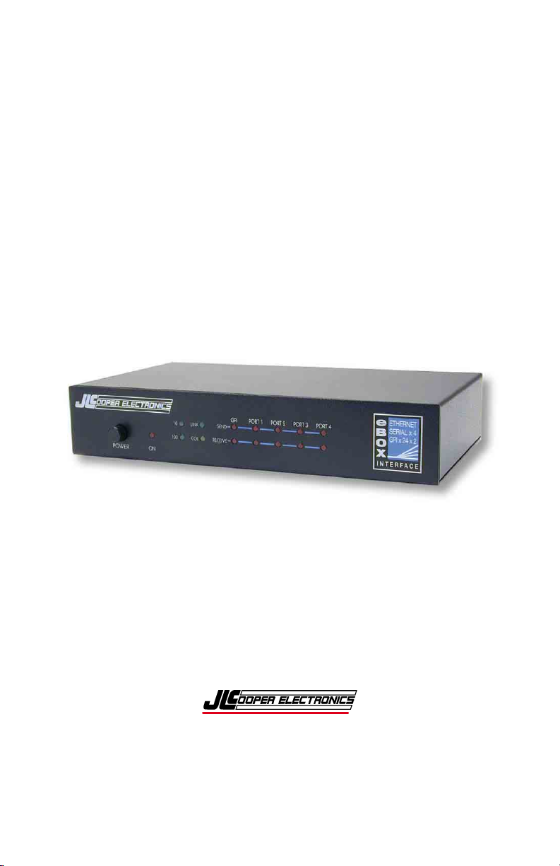
eBOX
Ethernet to Serial & GPI Interface
Users Manual
Page 2

eBOX and eBOX I/O are trademarks of JLCooper Electronics. All other brand
names are the property of their respective owners.
eBOX User’s Manual, Fifth Edition
Part Number 932095
2010 JLCooper Electronics, 142 Arena Street, El Segundo, CA 90245 USA
(310) 322-9990 ¬ (310) 335-0110 www.jlcooper.com
2
Page 3

Table of Contents
Introduction................................................................................... 6
Setup............................................................................................... 7
Unpacking................................................................................... 7
Connections................................................................................. 7
Operating Modes........................................................................... 8
Web Page Configuration......................................................... 8
eBOX Server Mode................................................................. 8
eBOX Client Mode ................................................................. 9
GPI to Serial Conversion ........................................................ 9
GPI to Ethernet Conversion .................................................... 9
Resetting eBOX Settings............................................................. 10
Initial Hardware Configuration ................................................ 11
eBOX Configuration Utility....................................................... 12
eBOX to Configure.................................................................... 13
eBOX Password Change........................................................... 13
eBOX Settings ........................................................................... 14
Configuration with Web Page Interface................................... 15
Operational Settings.............................................................. 17
eBOX IP Address.................................................................. 19
Port ............................................................................................... 20
Unused Switches................................................................... 20
GPI Outputs in GPI Conversion Modes ................................... 21
GPI Outs................................................................................ 21
3
Page 4

GPI Programmer Software........................................................ 22
eBOX GPI Tester Utility ............................................................ 25
eBOX Software for Apple Mac.................................................. 28
Installation ................................................................................ 28
Operation .................................................................................. 28
Preferences ............................................................................... 29
Password................................................................................... 30
Keysets ...................................................................................... 30
Programming Mode.................................................................. 31
Action Tabs ............................................................................... 32
MIDI Tab .................................................................................. 33
MIDI Machine Control (MMC)............................................ 33
Custom MIDI Messages ....................................................... 34
Special Tab................................................................................ 36
Delay Tab.................................................................................. 36
Keyboard Triggers.................................................................... 37
GPI Input Pins .......................................................................... 38
GPI Output Pins........................................................................ 38
GPI Preset Buttons ................................................................... 40
Serial Port Buttons.................................................................... 40
Serial Port Buttons.................................................................... 41
Serial Preset Buttons................................................................. 41
Serial Preset Buttons................................................................. 42
Live Mode.................................................................................. 43
Using the eBOX With a Router ................................................. 45
Using with eBOX I/O.................................................................. 46
4
Page 5

Technical Reference.................................................................... 47
Electrical Connections.............................................................. 47
Ethernet................................................................................. 47
Serial ..................................................................................... 48
GPI Port Pinouts ................................................................... 50
GPI Port Circuitry Details..................................................... 51
Power............................................................................................ 53
Troubleshooting .......................................................................... 54
Care and Service....................................................................... 55
Declaration of Conformity ......................................................... 56
RoHS Statement of Compliance ................................................ 57
JLCooper Electronics Limited Warranty ................................ 58
5
Page 6

Introduction
The eBOX is a general purpose interface box that converts 4 serial
communication ports and 24 GPI (General Purpose Interface)
inputs and outputs to 100/10baseT Ethernet. The serial ports can
be configured as EIA/TIA RS-232E (CCITT V.28) or as EIA/TIA
RS-422A ports. This can be performed easily in the field.
Additionally, the port direction can be configured as DTE or DCE
on each port independently.
The eBOX communicates over standard TCP/IP which allows is be
used with any host computer running any operating system that
uses TCP/IP protocol. The eBOX can also be connected to other
eBOXes to allow longer runs than traditional serial and GPI cables.
Since the eBOX uses TCP/IP, traffic can be routed over internal
LANs, wireless LANs, MANs, WANs and even over the public
Internet.
Most configuration can be accomplished through a web page
server built into the eBOX. Items such as port speed, parity, IP
address, remote IP address and TCP port are set using a standard
web browser. Settings are stored in nonvolatile memory.
Typically, the eBOX functions as a server, passively waiting for
client devices to connect to it. The device can be a computer or
another eBOX configured as a client. When the eBOX is
configured as a client, it will actively attempt to connect to the
server eBOX. Once this is accomplished, the either eBOX will
pass data received in the serial or GPI ports to the remote eBOX.
If there is no data received in the eBOX, the eBOX will not send
any TCP packets.
In addition, the eBOX can operate as a GPI to Serial Converter or
GPI to Ethernet Converter. In these modes, the eBOX will convert
GPI input triggers to deck commands.
6
Page 7

Setup
Unpacking
The eBOX package will contain the following items:
• eBOX
• Power Supply
• This Users Manual
• Four rubber feet
Connections
The eBOX connections are straightforward:
1. Plug the power supply into the eBOX.
2. Plug a network cable into the Ethernet jack.
3. Connect serial cables into ports 1-4.
4. Connect GPI cables into GPI ports.
7
Page 8

Operating Modes
The eBOX has five distinct modes of operation that are set by the
rear panel DIP switches. The DIP switches are read only at power
on so the eBOX must be power cycled for the changes to take
effect.
SW8 SW7 SW5
On X Off Web Page Configuration
Off Off
Off On
Off On On eBOX performs GPI to serial conversion
Off Off On eBOX performs GPI to Ethernet conversion
X = Don’t Care
Off eBOX is server at address specified on next
Off eBOX is client at address specified on next
Web Page Configuration
When DIP switch 8 is set to the ‘On’ position, the eBOX starts up
in the Web Page Configuration Mode. This allows the user to
configure the settings of the eBOX with a web browser such as
Internet Explorer 6. More information can be found in the section
‘Configuration with Webpage Interface’. The web page can be
found at the IP address set by DIP Switches 1, 2 and 3.
Note: The eBOX must be power cycled to switch to this mode.
page
page
Mode Configuration
eBOX Server Mode
When the eBOX is in the server mode, it waits for a client to
connect to it. The client can be another eBOX in client mode or it
can be a computer based application. The IP address and TCP port
of the eBOX is set by DIP switches 1, 2 and 3.
Note: The eBOX must be power cycled to switch to this mode.
8
Page 9

eBOX Client Mode
When the eBOX is set to client mode, it actively attempts to
connect to another eBOX in server mode. The IP address and TCP
port of the eBOX is set by DIP switches 1, 2 and 3.
Note: The eBOX must be power cycled to switch to this mode.
GPI to Serial Conversion
When the eBOX is in GPI to Serial Conversion Mode, it converts
GPI inputs into serial messages out to the four serial ports. The IP
address of the eBOX is set by DIP switches 1, 2 and 3 plus one.
The TCP port is fixed at 8000. The GPI Programmer Software
allows you to edit and upload the commands that are sent when
GPI inputs are triggered.
When the eBOX operates as a GPI to Serial Converter, it will send
to the to Serial Port A status requests on a periodic basis. Replies
from the deck will be used to establish the state of some of the GPI
Output pins, acting as tally lines. Refer to the section regarding
GPI Outputs in GPI Conversion Modes later in this manual.
Note: The eBOX must be power cycled to switch to this mode.
GPI to Ethernet Conversion
When the eBOX is in GPI to Ethernet Conversion Mode, it
converts GPI inputs into Ethernet messages specifically for Doremi
V1 and MCS video servers. The IP address of the eBOX is set by
DIP switches 1, 2 and 3 plus one. The TCP port is fixed at 8000.
The eBOX GPI Programmer Software allows you to edit and
upload the commands that are sent when GPI inputs are triggered.
When the eBOX operates as a GPI to Ethernet Converter, it will
send to the Doremi server status requests on a periodic basis.
Replies from the server will be used to establish the state of some
of the GPI Output pins, acting as tally lines. Refer to the section
regarding GPI Outputs in GPI Conversion Modes.
Note: The eBOX must be power cycled to switch to this mode.
9
Page 10

Resetting eBOX Settings
The eBOX settings can be forced to factory defaults by using the
reset button. The reset button is located behind the front panel. It
can be accessed via the small, unmarked hole to the right of the
Port 4 Send LED. The arrow in the picture below shows the
location of the hole for the reset button.
To reset the eBOX to factory defaults, simply press the button with
a long, thin object such as a paper clip and turn the power on. The
reset button can be released after the 5 Send and 5 Receive LEDs
stop flashing.
The eBOX factory defaults are:
IP Address 192.168.254.102
Subnet Mask 255.255.255.0
Gateway Address 192.168.254.198
TCP Port 23
Destination IP Address 192.168.254.103
Destination TCP Port 5000
Password
Serial Port Rate 38400 bits/sec
Parity Odd
Serial Port Timeout 5 mS
Maximum Buffer Size 128 bytes
password
eBOX Settings After Reset
After the eBOX settings are reset in this manner, you must power
cycle the eBOX to load those settings.
10
Page 11

Initial Hardware Configuration
IP Address
The IP Address of the unit depends on the position of DIP switches
1, 2 and 3. This is detailed in the table below. The address box
can accommodate numeric (nnn.nnn.nnn.nnn) or alphanumeric
(domain.name.com) network locations.
SW3 SW2 SW1 SW7 Mode IP Address
Off Off Off Off Server 192.168.254.102
Off Off Off On Client 192.168.254.103
Off Off On Off Server 192.168.254.104
Off Off On On Client 192.168.254.105
Off On Off Off Server 192.168.254.106
Off On Off On Client 192.168.254.107
Off On On Off Server 10.0.0.128
Off On On On Client 10.0.0.129
On Off Off Off Server 10.0.0.130
On Off Off On Client 10.0.0.131
On Off On Off Server 10.0.0.132
On Off On On Client 10.0.0.133
On On Off Off Server 172.16.0.128
On On Off On Client 172.16.0.129
On On On Off Server Set by user,
Default=192.168.254.102
On On On On Client Set by user,
Default=192.168.254.102
IP Address Configuration for eBOX
11
Page 12
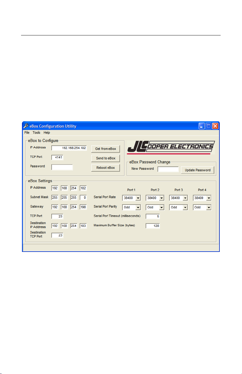
eBOX Configuration Utility
Beginning with version 1.09 firmware, a second TCP connection
was added. This allows the eBOX to be configured while the
eBOX is in use and avoids any compatibility issues with web
browsers. This is the recommended way to configure the eBOX.
To allow easy configuration of the eBOX, JLCooper has provided
a small Windows utility. The eBOX Configuration Utility is
shown below.
To use the utility, simply install and launch it.
12
Page 13

eBOX to Configure
In this section, enter the IP Address, TCP Port and Password of the
target eBOX that you wish to configure.
IP Address
This is IP Address of the target eBOX to configure.
TCP Port
This is the TCP Port of the target eBOX to configure. The TCP
Port for configuration is fixed at 4141. In most circumstances, you
will never have to change this however, if the eBOX is behind a
router using port forwarding, you may have to specify a different
port.
Password
If DIP switch 6 is set to the down position, the eBOX uses a
password to prevent unauthorized access. The default password is
‘password’.
Note: If the Password box contains any text, the eBOX Configuration
Utility will pad out the password with spaces and truncate the
password to 8 characters. If the Password box is empty, the eBOX
Configuration Utility will send no password.
eBOX Password Change
This section allows you to change the password of the eBOX.
Remember, if DIP switch 6 is set to the down position, the eBOX
requires the correct password in the ‘eBOX to Configure’ section.
The default password is ‘password’.
New Password
This is the area to enter a new password. The password can be up
to 8 characters in length.
Update Password
Clicking on this button sends the new password to the eBOX.
Note: The eBOX Configuration Utility will pad out the password with
spaces and truncate the password to 8 characters even if the Password
box is empty.
13
Page 14

eBOX Settings
This section allows you to change the operational settings of the
eBOX Ethernet and serial ports. These settings are identical to the
settings that appear on the configuration web page.
Device IP Address
IP address of this eBOX when SW1, SW2 and SW3=On.
Subnet Mask
The mask is a binary pattern that is matched up with the IP address
to turn part of the host ID address field into a field for subnets.
Gateway Address
IP address of gateway router that connects to other networks.
Port Number
TCP port of this eBOX when SW1, SW2 and SW3=On.
Destination IP Address
IP address of remote eBOX when SW1, SW2 and SW3=On. This
is used when eBOX is configured as a client (SW7=On).
Destination Port Number
TCP port of remote eBOX when SW1, SW2 and SW3=On. This is
used when eBOX is configured as a client (SW7=On).
Password
Eight character alphanumeric password that is embedded in the
Ethernet packet that prevents unauthorized eBOXes from passing
unintended packets. If the password protection feature is enabled
(SW6=Off) on either eBOX, then both eBOXes must have the
same password.
Baud Rate
Sets the port speed of the individual serial ports.
Parity and Parity Type
Enables or disables parity and sets parity type of the serial ports.
Serial Time Out
Sets the time that the eBOX will wait for data from the serial ports.
Max Buff Size
Sets the maximum buffer size of the serial ports.
14
Page 15

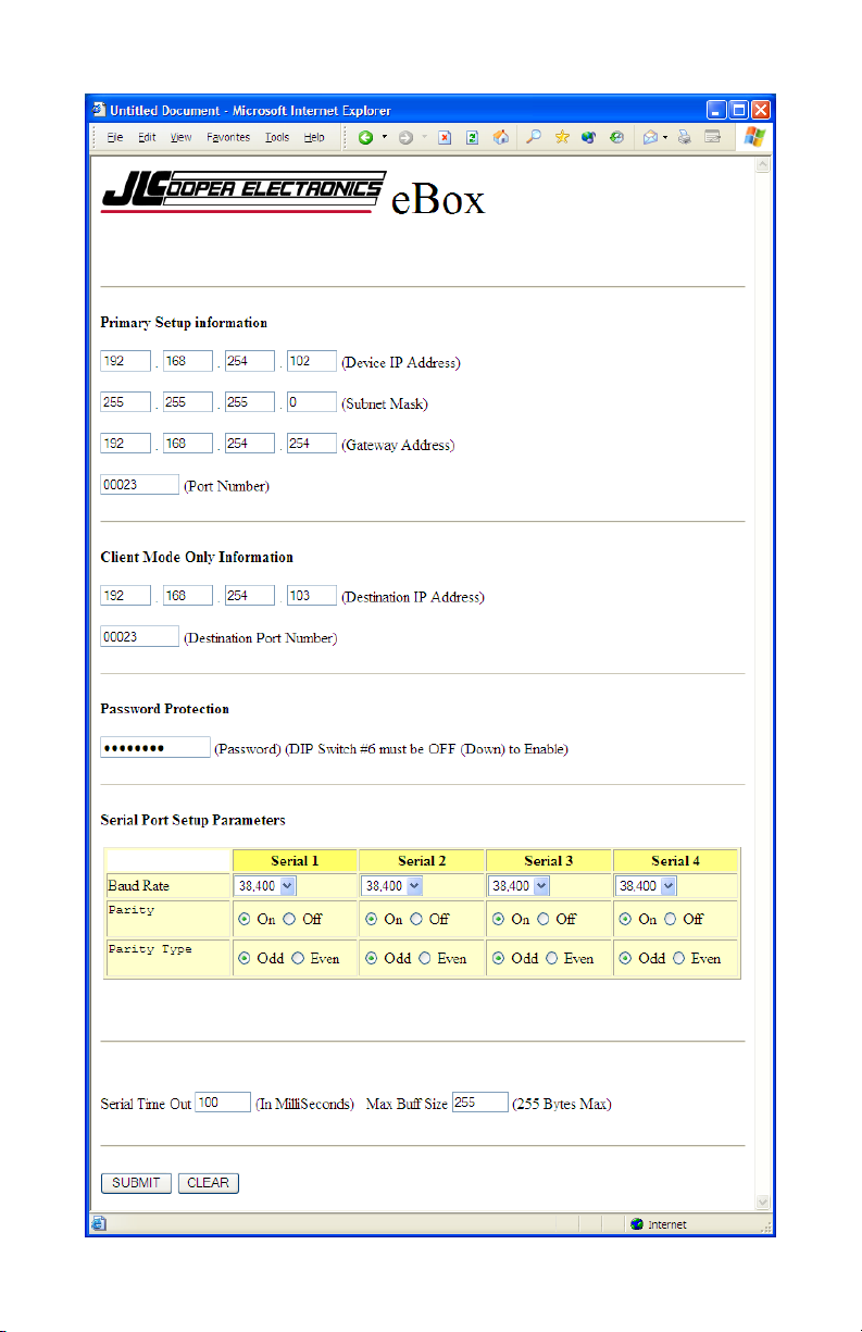
Configuration with Web Page Interface
Note: Beginning with version 1.09 firmware, the ability to configure the
eBOX with the eBOX Configuration Utility while the eBOX is in use
was added. For this reason, using the eBOX Configuration Utility to
configure the eBOX is the recommended method to configure the
eBOX.
When SW8 is set in the ‘On’ position, the eBOX allows access to
the configuration web page. On this page, various settings such as
port rate and parity, IP addresses and ports, and password can be
modified.
Note: The eBOX will not send Serial/GPI messages when the eBOX is
set to configuration mode.
This page is accessed by setting SW8 to the ‘On’ position and
typing
time, the normal operation of the eBOX is suspended. Make any
changes that are necessary for your system and click on SUBMIT.
These changes are stored in nonvolatile memory and are loaded at
power up.
Switch SW8 to the ‘Off’ position and power cycle the eBOX so the
changes are loaded.
The configuration web page is shown on the next page.
http://192.168.254.102 into your web browser. During this
Note: The configuration web page is always set to 192.168.254.102
regardless of the state of the DIP switches.
Note: In the configuration mode, the subnet mask is set to
255.255.255.0. This means that the eBOX will only see traffic from
computers with and IP address of 192.168.254.nnn. You will need to
change your computers IP address to 192.168.254.nnn where nnn =
any number except 0, 102 and 255. This will allow your computer to
access the configuration page of the eBOX.
15
Page 16
16
16
Page 17

Operational Settings
Device IP Address
IP address of this eBOX when SW1, SW2 and SW3=On.
Subnet Mask
The mask is a binary pattern that is matched up with the IP address
to turn part of the host ID address field into a field for subnets.
Gateway Address
IP address of gateway router which connects to other networks.
Port Number
TCP port of this eBOX when SW1, SW2 and SW3=On.
Destination IP Address
IP address of remote eBOX when SW1, SW2 and SW3=On. This
is used when eBOX is configured as a client (SW7=On).
Destination Port Number
TCP port of remote eBOX when SW1, SW2 and SW3=On. This is
used when eBOX is configured as a client (SW7=On).
Password
Eight character alphanumeric password that is embedded in the
Ethernet packet that prevents unauthorized eBOXes from passing
unintended packets. If the password protection feature is enabled
(SW6=Off) on either eBOX, then both eBOXes must have the
same password.
Baud Rate
Sets the port speed of the individual serial ports.
Parity and Parity Type
Enables or disables parity and sets parity type of the serial ports.
Serial Time Out
Sets the time that the eBOX will wait for data from the serial ports.
Max Buff Size
Sets the maximum buffer size of the serial ports.
17
Page 18

eBOX Security
The eBOX contains a basic security mechanism that prevents
unintended hosts or eBOXes from passing data through a secured
eBOX. An eBOX can be protected with password that is set on the
configuration web page. The password is stored in nonvolatile
memory and, is read upon power up.
When password protection is enabled, the sending eBOX embeds
the password in the transmitted IP packet. At the remote end, the
receiving eBOX must have password protection enabled AND
have a matching password.
The DIP switches are read only at power on so the eBOX must be
power cycled for any changes to take effect.
This security mechanism is only used in eBOX Server and eBOX
Client modes. SW6 should be set to the off position when used in
the GPI to Serial and GPI to Ethernet modes.
SW6
On Disable password protection
Off Enable password protection
Security Configuration
The effect of SW6 takes place immediately.
Note: If an eBOX has password protection is disabled, it will ignore the
password and act on any packets sent to it.
18
Page 19

eBOX IP Address
The IP address of the eBOX can be set by the rear panel DIP
switches or by the internal web page. As above, the DIP switches
are read only at power on so the eBOX must be power cycled for
the changes to take effect.
Here is a table of how IP address and the TCP port are set with the
DIP switches in eBOX Server and eBOX Client modes.
SW3 SW2 SW1 SW7 Mode IP Address Port
Off Off Off Off Server 192.168.254.102 23
Off Off Off On Client 192.168.254.103 23
Off Off On Off Server 192.168.254.104 23
Off Off On On Client 192.168.254.105 23
Off On Off Off Server 192.168.254.106 23
Off On Off On Client 192.168.254.107 23
Off On On Off Server 10.0.0.128 23
Off On On On Client 10.0.0.129 23
On Off Off Off Server 10.0.0.130 23
On Off Off On Client 10.0.0.131 23
On Off On Off Server 10.0.0.132 23
On Off On On Client 10.0.0.133 23
On On Off Off Server 172.16.0.128 23
On On Off On Client 172.16.0.129 23
On On On Off Server Set by user
On On On On Client Set by user
IP Address Configuration for eBOX Server and eBOX Client
modes
19
Page 20

Here is a table of how IP address and the TCP port are set with the
DIP switches in eBOX GPI to Serial and GPI to Ethernet
conversion modes.
SW3 SW2 SW1 IP Address Port
Off Off Off 192.168.254.103 8000
Off Off On 192.168.254.105 8000
Off On Off 192.168.254.107 8000
Off On On 10.0.0.129 8000
On Off Off 10.0.0.131 8000
On Off On 10.0.0.133 8000
On On Off 172.16.0.129 8000
On On On Set by user 8000
IP Address Configuration in GPI conversion
modes
Unused Switches
Switch 4 is currently not used.
20
Page 21

GPI Outputs in GPI Conversion Modes
GPI Outs
When the eBOX operates as a GPI to Serial or GPI to Ethernet
Converter, it will send to the Doremi server or to Serial Port A
status requests on a periodic basis. Replies from the server or deck
will be used to establish the state of some of the GPI Output pins,
acting as tally lines. The pins are presently defined as:
Pin Tally Function Pin Tally Function
1 Ground 14 Jog
2 Play 15 Shuttle
3 Record 16 -
4 Fast Forward 17 Servo Lock
5 Rewind 18 A1
6 - 19 A2
7 Stop 20 TC
8 - 21 -
9 Standby 22 Video
10 Cue Up 23 Assemble
11 Still 24 Insert
12 Forward Direction 25 -
13 Varispeed
GPI Tally Outputs in GPI Conversion Modes
Note: by default, the GPI Input pins are active low or 0 volts. That is,
events are triggered when the GPI Inputs are connected to ground or
driven to zero volts. This behavior can be modified with the eBOX GPI
Programmer Software.
21
Page 22

GPI Programmer Software
The GPI Programmer Software pictured below allows you to
program custom messages and behaviors when the eBOX is in
either eBOX GPI to Serial and GPI to Ethernet conversion mode.
eBOX IP address
This is the IP address of the eBOX you want to configure.
eBOX TCP Port
This is the TCP port of the eBOX you want to configure. The
eBOX TCP port in the GPI to Serial and GPI to Ethernet
conversion modes is fixed to TCP port 8000.
Connection State
This window shows the status of the connection to the eBOX you
want to configure.
Connect / Disconnect
This allows you to establish or break the connection to the eBOX
you want to configure.
22
Page 23

Status Window
This window shows additional status messages of the connection
to the eBOX you want to configure. In addition, you will also see
the firmware version of the connected eBOX.
eBOX Programming
The parameters in this box are settings that will be downloaded
into the eBOX.
eBOX IP address
This will be the IP address of this eBOX when SW1, SW2 and
SW3=On.
Subnet Mask
This will be the subnet mask of the eBOX.
Gateway Address
This will be the IP address of gateway router which connects to
other networks.
Port Number
This will be the TCP port of this eBOX when SW1, SW2 and
SW3=On.
Destination IP Address
IP address of remote eBOX when SW1, SW2 and SW3=On. This
is used when eBOX is configured in the GPI to Ethernet mode or
the eBOX is in client mode.
Destination Port Number
TCP port of remote eBOX when SW1, SW2 and SW3=On. This is
used when eBOX is configured in the GPI to Ethernet mode or the
eBOX is in client mode.
Auto Calculate Checksum
Automatically appends a Sony type checksum to the end of each
message.
Suppress Header and Status Request
This disables Doremi message headers and VTR status requests.
Doing this allows you to use the eBOX in applications that do not
involve a VTR.
Serial Ports Baud Rate
Sets the port rate of the individual serial ports.
23
Page 24

Serial Ports Parity / Type
Enables or disables parity and sets parity type of the individual
serial ports.
GPI Pins
These are the pins on the GPI Input connector.
Commands
These are the commands that are sent when the GPI input is
triggered. The command can be triggered on either transition
which is set by the invert checkbox described below. Each byte
must be a two digit hexadecimal number.
Invert
Normally messages are triggered when a GPI input pin is shorted
to ground. Checking this box allows the messages to be triggered
when a GPI input pin is opened or is driven to +5 volts.
Send to Ports
This allows you to specify which serial port(s) the commands are
sent.
Send to eBOX
Clicking this button downloads all the parameters to the eBOX.
During the download, the eBOX will momentarily stop responding
to GPI inputs. This is normal. The serial messages and serial port
routings will be effective immediately. However, changes to the
IP settings and serial port settings take effect after a power cycle.
24
Page 25

eBOX GPI Tester Utility
The GPI Tester Utility pictured below allows you to perform basic
tests with your eBOX, eBOX I/O (if equipped) and connected
customer equipment. This is intended to be a diagnostic tool to aid
you in setting up a server eBOX. The GPI Tester Utility can be
used to connect to an eBOX configured for server mode.
The GPI Tester Utility can not connect to an eBOX:
• When configured as a client eBOX,
• When configured as a GPI to Serial converter,
• When configured as a GPI to Ethernet converter or,
• When connected to another eBOX or application.
25
Page 26

eBOX IP address
This is the IP address of the eBOX you want to test.
eBOX TCP Port
This is the TCP port of the eBOX you want to test. The eBOX
TCP port in the server mode is TCP port 23 by default. This can
be configured for any TCP port.
Connection State
This window shows the status of the connection to the eBOX you
want to test.
Connect / Disconnect
This allows you to establish or break the connection to the eBOX
you want to test.
Status Window
This window shows additional status messages of the connection
to the eBOX you want to test. In addition, you will also see the
firmware version of the connected eBOX.
GPI Inputs
These checkboxes indicate the state of the input pins on the GPI
Input connector. A check mark indicates that the corresponding
pin is in the active state (logic low or 0 volts). The absence of a
check mark indicates that the corresponding pin is in an inactive
state (logic high or 5 volts). Clicking on a checkbox will cause the
eBOX GPI Tester Utility to send a GPI Query command to update
the state of the checkbox.
GPI Outputs
Sets selected GPI Output to active state (logic low or 0 volts). All
other GPI Outputs are set to inactive state (logic high or 5 volts).
All Off
Sets all GPI Outputs to inactive state (logic high or 5 volts).
26
Page 27

Test All
Sets all GPI Outputs to the inactive state (logic high or 5 volts) and
sets each GPI Outputs to the active state (logic low or 0 volts) one
by one in succession as shown below.
1 → 2 → 3 … 22 → 23 → 24 → 1 → 2 → 3 …
Clicking the button again will stop the sequence.
Query GPI
An eBOX sends a GPI Status message in any of the following
cases:
• whenever any of its GPI Inputs change states,
• periodically every 5 seconds or,
• when a GPI Query command is received.
Clicking the Query GPI button sends a GPI Query command to the
connected eBOX causing the eBOX to immediately return the
states of its GPI Inputs. Clicking the Query GPI button is a good
way to verify that the eBOX GPI Tester Utility is still connected to
the eBOX under test.
Note: The eBOX GPI Utility does not use the Password protection
feature of the eBOX so that feature will have to be disabled by setting
DIP switch 6 to the ‘ON’ position.
27
Page 28

eBOX Software for Apple Mac
Installation
The installer puts the folder eBox in the /Applications folder. This
folder contains the eBox Control Center application and the eBox
Uninstaller. The installer also places eBox_StartupItem in
/Library/StartupItems and eBoxMidiDriver in /Library/MIDI
Drivers.
To uninstall run the eBox Uninstaller located in
/Applications/eBox. Select the items to uninstall, then click on the
Uninstall button.
NOTE: Currently the uninstaller is unable to remove the eBox Control
Center application.
Operation
After restart run eBox Control Center. This application serves as
the editing application just like the applications for our control
surfaces. However, it also can be used as a front end for the eBox.
You switch between these two modes of operation with the
Programming / Live Mode switch located just above the logo.
28
Page 29

Preferences
The preferences are where you set the IP Address, port and the
optional password.
NOTE: The password feature is not currently implemented.
There are several IP Addresses and Ports built in to the eBox.
They are set using the dip switches on the back of the eBox. Refer
to the eBox manual for details. You need to set the software to use
the same address and port as the hardware. The available ports are
listed in the popup menu. With the correct dip switch settings, and
by choosing Custom from the popup, you can define your own IP
address and port.
29
Page 30

Password
If you check the Use Password checkbox, you can define an eight
character password that will be sent as part of every message to
and from the eBox. This must match the password set in the eBox
hardware. Refer to the eBox manual for setting up the password.
Keysets
This software uses keysets like our control surface software.
Different keysets can be set up for different applications, for
example, a keyset for Pro Tools and another one for FCP. In Live
Mode the eBox, software will automatically use the correct keyset
for the front application.
To create a new keyset, go to New Keyset in the File menu. In the
dialog that opens up, navigate to the application that the keyset will
be used with, such as Pro Tools, FCP, etc. and click on Open.
30
Page 31

Use the Keysets menu to switch between the various keysets that
you have created.
When the eBox Control Center is in the background or not
running, the eBox driver checks to see what application is in front
then uses the keyset created for that application. If an application
has no keyset, then the eBox driver uses a permanent keyset named
Global. Although the Global keyset can be programmed just like
keysets for specific applications, it is probably best to leave it
blank. Otherwise, you might start your tape machines playing
while browsing in Safari :)
Keysets, and any changes you make to them, are stored
automatically in the eBox's preference file. There is no need to
Save or Open on a regular basis. If you want to make a copy of
your work for backup or to move to another Mac, use Open
Archive and Save As Archive in the File menu. These commands
store and retrieve all of your keysets in a single file.
Programming Mode
In programming mode, you click on a button, and its information
appears in the Inspector window. Here, you can give the control a
name and a set of actions to perform when it is clicked.
31
Page 32

You set up an action in one of the tabs (for example, GPI, MIDI,
Special, Delay) then click on Add Action. You can keep adding
as many actions as you want. They will be performed in order
when the button is pressed in Live Mode.
Action Tabs
The tabs in the inspector window vary slightly depending on what
type of control is selected. All controls will have the MIDI,
Special and Delay tabs. GPI Output buttons and GPI Preset
buttons will have a GPI Tab, and Serial Port and Serial Preset
buttons will have a Serial Tab.
32
Page 33

MIDI Tab
The MIDI tab is where you can assign MIDI message to a control.
These messages will be received by any running MIDI application
that is connected to the eBox Software. The procedure for
connecting MIDI applications varies from application to
application and will be covered in those applications’ manuals.
MIDI Machine Control (MMC)
You can assign one of several common MIDI Machine Control
(MMC) messages by clicking on the MIDI Machine Control radio
button and selecting a message from the popup menu.
33
Page 34

Custom MIDI Messages
By clicking the Custom radio button, you can define your own
MIDI message. The different message types will appear in a
popup menu.
34
Page 35

Depending on the type of message you choose, other editing
controls will appear. If the message type you have chosen has a
channel, you can either type a number from 1 - 16 in the Channel
field, or use the up and down arrows next to it. If the message also
includes one or two data bytes, the data byte editors will appear.
You can type a number from 0-127 or use the up and down arrows.
If you check Follows Control, then pressing a button in Live
Mode will cause that data byte to have a value of 7Fhex (127
decimal) and releasing the button will give it a value of 00hex,
In this example, one MMC Command and one Custom MIDI
Command have been assigned to a control.
35
Page 36

Special Tab
The Special Tab is not currently implemented.
Delay Tab
You can use the Delay Tab to set a delay between two actions.
Simply move the slider from 0 to 2 seconds then hit the Add/Insert
button.
If a GPI Preset button was programmed as in the following
example, pressing it in Live mode would close some GPI contacts,
wait, send a Record Strobe to all connected MIDI applications,
wait then send another MIDI message.
36
Page 37

Keyboard Triggers
For any buttons that trigger an output (actually, all buttons except
for the GPI IN buttons), you can also choose a keyboard trigger
that will perform the same actions as clicking on the button. The
trigger can optionally be passed on to the front application, with or
without a delay. The delay can be from 0 - 1 second. This lets you
do things like hit the space bar in Pro Tools to start playback, but
have the eBox turn off the studio monitors and wait a half a second
before sending the space bar to Pro Tools.
To set a keyboard trigger, click in the field next to Trigger with
Keystroke then type the trigger Character, modifier keys and all.
At any time, you can change the modifier keys by clicking on the
modifier checkboxes.
Because the keyboard triggers are assigned to specific applications,
they only operate when those apps are in front. Therefore, they
will not interfere with Microsoft Word, or your billing software.
NOTE: Keyboard triggers are disabled in the Global Keyset to prevent
unwanted interference with other applications.
All buttons can be either latched or momentary, and you can
choose to have them repeat their actions while the button is down.
37
Page 38

GPI Input Pins
The top group of buttons each represents Individual GPI pins.
There are three rows of input pins and three rows of output pins.
For the Input pins, you can program what happens when an
individual input pin is changed by some external hardware.
Currently the GPI Input pins can generate MIDI Messages and
Delays.
GPI Output Pins
Each GPI Output pin button can change the state of its pin, without
affecting the other pins. In the GPI tab, you can create a GPI
action that closes the contact when the button is pressed and opens
it when released. If you click on the Invert check box, then it
opens the contact on the button press and closes it on release.
Currently the Special Tab is not implemented. But even without it
you have the ability to do something like turn on a contact then
delay up to 2 seconds then turn it off again, plus send a MIDI
message to an application, and this can be triggered by a keystroke
that also does something useful in another program, like Pro Tools.
38
Page 39

Unlike serial ports, where the input and output signals are carried
over the same cable, and are usually going to the same device, GPI
inputs and outputs are separate entities. They may or may not be
connected to the same device. This is why they can be
programmed independently. However, when an input and output
pin is connected to the same device and you want them both to
perform the same actions, you can program the GPI Output pin
first, then click on Apply to GPI In. This will transfer the output
pin’s settings to the corresponding input pin.
39
Page 40

GPI Preset Buttons
The four GPI Preset buttons are similar to the GPI Output buttons,
except that they allow you to affect all of the GPI outputs at once.
In the GPI tab you can choose for each Pin, whether to have it
follow the button state, invert the button state, toggle with each
button press, or do nothing.
40
Page 41

Serial Port Buttons
Each of the four Serial Port buttons lets you send a message to a
serial port. It can be a Sony 9-Pin serial command, or any arbitrary
string that you can type in. The serial message can be combined
with MIDI and Delay actions. The Special tab is not currently
implemented.
The custom messages can be entered and displayed in either
decimal, hex or ASCII notation. The notation style is chosen with
the radio buttons at the bottom of the window.
Since the Serial Port buttons only send one command, they are
most useful if you have a single command that you send to a port
frequently. They are also useful displaying the name of the device
the port is connected to.
41
Page 42

Serial Preset Buttons
The Serial Preset buttons are more flexible. There are four banks,
each bank containing five F-Keys and five transport buttons.
There are four Gang buttons above each bank. These buttons let
you direct the bank’s output to one or more serial ports.
While more than one of the five F-Keys can be active at once, the
transport buttons act like “radio” buttons. That is, only one can be
active at once. Sorry, you can’t Record in Rewind. It’s a feature.
If that’s actually a problem, let us know.
42
Page 43

Live Mode
In live mode, the Inspector window is hidden, and the main
window’s appearance changes slightly.
The GPI Input Buttons change to indicators to show the state of
the GPI Inputs. They are not clickable since GPI Input actions are
only initiated by the external hardware.
In Live Mode, the GPI Output, GPI Preset, Serial Port and
Serial Preset buttons all initiate the actions they were assigned in
Programming mode.
Activity indicators also appear next to the GPI Output Buttons and
the Serial Port Buttons, since there are times when the state of a
GPI pin or serial port might be different from the state of the
button.
43
43
Page 44

In Programming mode, only one button (the one being
programmed) ca
be active. The exception is the Serial Preset Transport Controls.
Within each preset bank, each transport control is mutually
exclusive.
W
hen the eBox Control Center is the front application in Live
mode, you determine which keyset is active using the Keyset
menu. If the eBox Control Center is in th
ru
nning at all, the eBox driver automatically switches keysets
based on the front application. If there is no keyset for the
frontmost application, then the driver uses the Global keyset.
W
hen the eBox Control Center is not the front application, you can
use the keyboard triggers you defined in Programming Mode to
initiate the actions you assigned to the various buttons.
If
the eBox Control Center is visible in the background, and in
Live Mode, then its indicators will still display the states of the
GPI Input and Output Pins and the Serial Port Inputs.
n be active at once. In Live mode, any button can
s
e background, or not
44
Page 45

sing the eBOX With a Router U
p
p
In this section, we will explain how to configure the eBOX to work
with a router. In this example, we will show how to configure two
eBoxes behind a router. This same information also applies
normal ope
ration of the eBOX with different port numbers.
to
The TCP Port that the eBOX uses for configuration is fixed at
4141. However, if the eBOX is behind a router and the router i
configured to use Port Forwarding to remap the TCP connectio
the eBOX, you may have to use a different port. A good exam
of this is if you have 2 eBOXes at a remote site. In the exam
s
n
ple
ple
below, there are two eBOXes behind a router. The router is
onfigured to pass configuration packets coming to the router at IP
c
Address 12.34.56.78, TCP Port 4141 to the first eBOX at IP
Address 192.168.254.102, TCP Port 4141. Additionally, the route
is also configured to pass configuration packets coming
uter at IP Address 12.34.56.78, TCP Port 4142 to the second
ro
to the
eBOX at IP Address 192.168.254.103, TCP Port 4141.
IP Address = 12:34:56:78
TCP Port = 4141
IP Address = 12:34:56:78
TCP Port = 4142
Router
Port Forwarding Table
4141→192.168.254.102:4141
4142→192.168.254.103:4141
IP address = 19
2.168.254.102
ort = 4141
TCP
eBox #1
eBox #2
IP address = 192.168.254.102
TCP
ort = 4141
r
45
Page 46

Using with eBOX I/O
The eBOX GPI inputs and outputs are CMOS compatible circuits.
The CMOS GPI inputs require that the input signals be 0 to 5 volts
and referenced to ground. The CMOS GPI outputs can deliver 0
5 volts at up to +/- 6mA and referenced to ground.
In many cases, this will be compatible with your equipment.
However, in some cases, there will be the end user equipment ma
not be compatible with 0 to 5 volt requirements of the eBOX GPI
inputs and outputs. In this case, the eBOX I/O must be used. Each
eBOX I/O buffers 8 inputs and 8 outputs. The inputs are buffered
with an optoisolators while the outputs are buffered with a dr
relay contact. Up to three eBOX I/Os can be used with a single
eBOX.
3 1 2 4
eBOX I/O #1
GPI 1-8
3 1 2 4
eBOX I/O #2
GPI 9-16
3 1 2 4
eBOX I/O #3
GPI 17-24
to
y
y
46
Page 47

Technical Reference
Electrical Connections
Ethernet
This eBOX port is just like an Ethernet port on a computer, to
connect it to a hub, switch or router, use a straight through cab
To connect it to another eBOX or computer, use a crossover cable.
The eBOX supports IEEE 802.3u clause 28 Auto-Negotiation
which automatically senses the Ethernet port speed & duplex
operation and chooses the highest performance settings.
In addition, four LEDs on the front panel that indicate various
operating
conditions of the Ethernet port. These LEDs are:
• Link
• 100BaseT activity
• 10BaseT activity
• Collision
le.
47
Page 48

Serial
The four serial ports along the to
connectors which can be configu
operation. I
to appear as
n RS-422 mode, the eBOX direction can be configured
a Controller or a Device. In RS-232 mode, the eBOX
appears as a DCE or DTE.
p of the rear panel are 9 pin D-Sub
red for RS-232C or RS-422A
Mode RS-232C RS-232C RS-422A RS-42
Direction
Left SW
Right SW
Pin 1
Pin 2
Pin 3
Pin 4
Pin 5
Pin 6
Pin 7
Pin 8
Pin 9
To Device To Computer To Deck To Controller
Out In Out In
In In Out Out
not used not used not used not used
Receive Transmit Receive A Transmit A
Transmit Receive Transmit B Receive B
not used not used Ground Ground
Ground Ground Ground Ground
not used not used Ground Ground
not used not used Receive B Transmit B
not used not used Transmit A Receive A
not used not used not used not used
2A
Serial Port Configuration
48
Page 49

Older versions of the eBOX used DIP switches to configure the
the ports. In RS-232 mode, the RS-422 ICs must be mode of
removed. These ICs are marked 89C22.
Mode RS-232C RS-422A RS-422A
Direction
SW1
SW2
Pin 1
Pin 2
Pin 3
Pin 4
Pin 5
Pin 6
Pin 7
Pin 8
Pin 9
X = Don’t Care
To Computer To Deck To Controller
On Of Of
X On Off
not used not used not used
Transmit Receive A Transmit A
Receive Transmit B Receive B
not used Ground Ground
Ground Ground Ground
not used Ground round G
not used Receive B Transmit B
not used Transmit A eceive A R
not used not used not used
f f
Serial Port Configuration
49
Page 50

GPI Port Pinouts
The GPI ports on the rear of the eBOX ar
onnectors. The GPI In connector has 24 TTL/CMOS compatible
c
e 25 pin D-sub
inputs with internal pull-ups to +5 volts. The GPI Out connector
has 24 TT S c ut th , pin 1
is the g n -25 GP
L/CMO ompatible o puts. On bo connectors
round refere ce and pins 2 are the I signals.
When eBOXes connected together in a nt/server ner
clie man
establish a connection, both client and server eBOXes will send the
state of its n ports to ch other s an be sho n the GPI
Out port on the remote After that, changes to a GPI In port
will cause OX to send a GPI message to the remote eBOX.
Additiona eBO end ssa
GPI I ea o it c wn o
eBOX.
an eB
lly, the Xes will s a GPI me ge every 5
seconds to keep the connection alive and to refresh the state of the
GPI outpu
ts.
A packet is sent whenever a change to the GPI In is sensed. At
present, it is sampled a ry 20 onds. This can be
bout eve millisec
changed via the configuration web page.
LSB
Byte1 Pin 9 Pin 8 Pin 7 Pin 6 Pin 5 Pin 4 Pin 3 Pin 2
Byte2 P Pin 16 Pin Pin Pin 10 in 17 Pin 15 14 Pin 13 12 Pin 11
Byte3 P Pin 24 Pin 23 Pin 22 Pin 21 Pin 20 Pin 19 Pin 18 in 25
MSB
eBOX GPI In/Out Pinouts
50
Page 51

GPI Port Circuitry
The eBOX GPI input and output circuits are detailed in th
Details
e
following section.
The inputs of the eBOX GPI ports are CMOS inputs. The input
circuitry has a 4700 ohm pullup resistor to +5 volts as refere
pin 1 of the GPI Input Port.
to
nced
Note: Because the inputs are CMOS, the input voltage MUST be
limited to voltage levels between 0 and 5 volts. If this is not possible,
consider using the eBOX I/O.
5 Volts
4700Ω
74HC244
Detail of GPI Input
he internal pullup resistor insures that the input pin is set to a
T
nown st he d fault s ate of e GPI nputs +5 vo ts or
k ate. T e t th I is l a
stat 1’ G es it T ter ull
logic e of ‘ in the PI m sage b map. he in nal p up
or a o m ‘dry con o
resist lso all ws a si ple switch or tact’ t be
cte e P t d d o th
conne d betw en a G I Inpu pin an groun as sh wn in e
example below.
5 Volts
4700Ω
2
1
GPI Input Example with Pushbutton Switch
74HC244
51
Page 52

The outputs of the eBOX GPI ports are also CMOS. The output
signal is referenced to pin 1 of the GPI Output Port. The GPI
Outputs are rated to +/- 6mA. If this is not sufficient for you
application, conside
r using the eBOX I/O.
r
Note: Because the inputs are CMOS, the output voltage MUST be
limited to voltage levels between 0 and 5 volts. This can occur if
driving a circuit that is powered by
this is not possible, consider using
74HC
a voltage higher than 5 volts. If
the eBOX I/O.
374
The exampl
Detail of GPI
Output
e circuits below shows a GPI Output driving an LED.
5 Volts
74HC374
GPI Output Example #1 with LED
74HC374
2
1
2
1
GPI Output Example #2 with LED
52
Page 53

Power
The eBOX requires a 9 volt DC, center positive power supply
capable of delivering at least 500 milliamps. The unit com
a
power supply appropriate for the country in which the unit was
sold. If you need a power supply specific to your location, please
tact your local distributor or JLCooper Electronics.
con
Location JLCooper Part
North America PSDC117
Europe PSDC230
Approved Power Supplies
Warning: Using a power supply other than the units specified in the
above table can result in damage to the eBOX and/or other equipment
which is not covered by the JLCooper Factory Warranty.
Number
es with
53
Page 54

shooting Trouble
If for some reason the eBOX does not give you the expected
results, take a moment to do some investigating. The most
important concept is that you have your eBOX connected properly
as outlined in Installation and Use. Take a moment to double
check your setup.
• W ate o
hat is the st f the DIP switches?
• Do the 10 red LEDs flash alternately at power up?
• Do the Link and 100 (or 10) LEDs light up?
• In any mo
(ping 192.168.254.102)?
• If you are using the password protection feature, is
enabled in both eBOXes?
• In webpage configuration mode, can you
with it using the web page?
• In normal client or server mode, can you communicate
with it using the eBOX Configuration Utility?
• The ARP Cache in the host application may have the
incorrect entry for the eBOX's IP address. Try clearing
the ARP cache (arp -d in Windows).
• In normal server mode, if you telnet to the eBOX, do
you see a short packet of unprintable characters every 5
seconds as shown in the screenshot below?
de, can you ping it
it
communicate
54
Page 55

If you are using the eBOX C
the eBOX for the settings to
A common problem is forgetting to turn the power switch on
turning the unit on after the software application has launche
In addition, the JLCooper website (www.jlcooper.com
contain up to date in
tr
oubleshooting.
If all el f ent
at: serv @
se ails, you can contact the JLCooper Service Departm
ice jlcooper.com
formation on drivers, applications and
onfiguration Utility, be sure to reboot
take effect
or
d.
) will
.
Care an
If prope
troublefree OX is built in a rugged
metal e lo
Clean w h
foreign ma
There are n
JLCooper E the last page
for deta d
d Service
rly cared for, your eBOX should provide years of
performance. While the eB
nc sure, please avoid dropping the eBOX.
it a soft, damp cloth. Do not allow liquids, dust or other
tter to get inside the unit.
o user-serviceable parts in the eBOX. Please refer to the
lectronics Limited Factory Warranty on
ile warranty and service information.
55
Page 56

Declaration of Conformity
JLCooper Electronics declares that the product named below conforms to:
Low Voltage Directive (LVD) 2006/95/EC
(Superceded LVD73/23/EEC) on 16th January 2006.
Low Voltage Directive
(Directive 73/23/EC has recently been the subject of a codifica
requiring a new number)
Warning: The installer is responsible for protection against personal contact
with all live connections to power supplies, w
Company Address:
142 Arena Street
El Segundo, CA, 90245 U.S.A.
Product Name: eBOX I
roduct Type: Network Interface
P
Model Number: eBOX
Date of Issue: 16 September 2009
Authorized by:
Title of Authority: Quality Assurance
Declaration Reference: CE/EEC2007TLL
(LVD) 73/23/EEC
tion,
eBOX
hich contain hazardous voltages.
nterface
56
Page 57

nce RoHS Statement of Complia
June 28, 2006
Re: eBOX
This is a declaration that the items described (herein as RoHS “Class 1”) do not
contain one or more than one:
RoHS restricted substances above the homogeneous material concentration limit
hreshold Level) per the EU/RoHS directive effective July 1, 2006 and
(T
amendi
ng document(s).
JLCoop r Electronics products will meet MIL-I 45208. The Company is
current 0, after which feasibility
researc
R
H
Cadmium (Cd) 100ppm (0.01%)
Lead (Pb) 1000ppm (0.1%)
M
Hexavalent Chromium
Polybrominated B
Polybrominated Diphenyl Ethers
Supplier evidence of compliance on
requirements of ISO 9000:2000. Whe
ISO 9000:2000 Quality an
S
Thomas L. Lowry
Quality Assurance Department
e
ly implementing procedures for ISO 9000:200
h will begin for ISO 14000 considerations.
oHS Class 1 OEM Products:
azardous Substance Allowed PPM Level
ercury (Hg) 1000ppm (0.1%)
(CrVI) 1000ppm (0.1%)
iphenyl's (PBB's) 1000ppm (0.1%)
(PBDE's) 1000ppm (0.1%)
file meets or exceeds trace ability
re feasible, JL Cooper seeks suppliers with
d ISO 14000 Environmental Certification.
incerely,
57
Page 58

rranty JLCooper Electronics Limited Wa
JLCooper Electronics ("JLCooper") warrants this product to be free of defects in materials or
w
orkmanship for a period of 12 months from the date of purchase. This warranty is non-
transferable a
warranty, c
9990 and talk to a service technician. If necessary, a Return Authorization number may be
issued. For our customers outside th
our Dealer or Distributor, since they may offer their own service or support policy. If local
y
support is not obtainable, please send a FAX to JLCooper's Service Department at +1 310 335
0110 with a detailed description of the service required. Upon issuance of return authorization,
the product should be packed in the original shipping materials and shipped pre
insured to: Service Departm
0245. Please include the following: copy of the sales receipt, your name and address (no P.O.
9
Boxes, please), a brief description of the problem, and any other related items discus
the service department and considered necessary to evaluate the product or effect a repair. T
return authorization number must be clearly written on the outside of the package. JLCoop
ill at its option, without charge for parts or labor, either rep
w
r unit. Carriage, insurance, customs duties, impounds, tariffs, taxes, surchanges, brokerage
o
fees and other shipping costs are not covered by thi
ound time at the factory is approximately 15 business days from receipt of product to
ar
shipping. Your actual turn around time will include return shipping. Actua
will vary depending upon many factors including the repeatability of th
complaint, the availability of parts required for repair, the availabilit
needed to evaluate the product if necessary. Priority services are availab
These should be discussed with the service technician at the time the r
issued. This warranty provides only the benefits specified and does not co
needed as result of acts beyond the control of JLCooper including but n
failure to operate in accordance with the procedures outlined in this ow
cover damage from accident, negligence, using incorrect power supply, modification,
it
alteration, improper use, unauthorized servicing, tampering, ingress of foreign mat
damage from natural or man-made events such as, but not limited to flooding
electrostatic discharge, tornadoes, earthquake, fire, civil unrest, war, terrorism, etc.
HE DURATION OF ANY OTHER WARRANTIES, WHETHER IMPLIED OR EXPRESS,
T
INCLUDING
MERCHANT D
WARRANTY HEREIN. JLCOOPER HEREBY EXCLUDES INCIDENTAL AND
CONSEQUENTIAL DAMAGES, INC UDING BUT NOT LIMITED TO: LOSS OF TIME,
INCONVENIENCE, DELAY IN PERF MANCE OF THIS WARRANTY, THE LOSS OF
USE OF THE PROD
EXPRESS OR IMPLIE
ABILITY APPLICABLE TO THIS PRODUCT OOPER SHALL NOT BE LIABLE FOR
DAMAGES OR LOSS RESULTING FROM THE NEGLIGENT OR INTENTIONAL ACTS
OF THE SHIPPER OR HIS CONTRACT FFILIATES. THE CUSTOMER SHOULD
CONTACT THE SHIPPER FOR PROPER CLAIMS PROCEDURES IN THE EVENT OF
DAMAGE OR LOSS RESULTING FROM SHIPMENT. THIS WARRANTY SHALL BE
GOVERENED BY THE LAWS OF THE STATE OF CALIFORNIA.
nd the benefits apply only to the original owner. Proof of purchase in the form of
ales receipt is required for warranty coverage. To receive service under this
d san itemize
ustomers in the United States should contact the JLCooper factory at (310) 322-
e United States, it is recommended that you first contact
ent, JLCooper Electronics, 142 Arena Street, El Segundo, CA
air or replace the defective part(s)
s warranty. JLCooper's normal repair turn
l turn around time
e customer's reported
of related products
y
le at additional cost.
eturn authorization is
ver defects or repairs
ot limited to: abuse,
ner's manual; nor does
BUT NOT LIMITED TO THE IMPLIED WARRANTY OF
ABILITY, IS LIMITE TO THE DURATION OF THE EXPRESS
L
UCT OR COMMERCIAL LOSS, AND FOR BREACH OF ANY
OR
D WARRANTY OF MERCHANT-
. JLC
A
paid and
sed with
ter; nor for
, lightning,
he
er
58
 Loading...