

JL Audio 94657, STEALTHBOX SB-POL-GNRLSPKR/MX650 Installation Manual

Thank you for choosing a JL Audio Stealthbox® for your automotive sound system.
With proper installation, your new vehicle-specific enclosed subwoofer system
will deliver years of listening pleasure.
We strongly recommend that you have your new Stealthbox® installed by your
authorized JL Audio dealer. The installation professionals employed by your
dealer have the necessary tools and experience to disassemble and reassemble
your vehicle properly. If you prefer to perform your own installation, please read
this installation guide completely before beginning the process.
If you choose to per form the installation yoursel f, it is absolutely
vital that the Stealthb ox
®
be properly mo unted to the vehicle
according to these instr uctions. Failure to mount the enclosure
properly presents two problems:
1) The sub -bass performance will suf fer due to the movement of the
enclosure caused by the force exerted by the woofer(s).
2) A l oose enclosure presents a serious s afety hazard in the event of a
collision or sudden deceleration.
INSTALLATION
DI FFIC ULT Y:
ESTIMATED TIME:
12 HOURS
Continued on Next Page
2
5
OUT
OF
SB-POL-GNRLSPKR/MX650 INSTR_SKU# 011502
INSTALLATION GUIDE
for the
SB-POL-GNRLSPKR/MX650
SKU# 94657
2016 & Up Polaris General
Enclosure Type: Sealed
Driver Type: MX650-CCX-SG-TLD-B
Nominal Impedance: 4 ohms
Continuous Power Handling: 60 watts (RMS method)
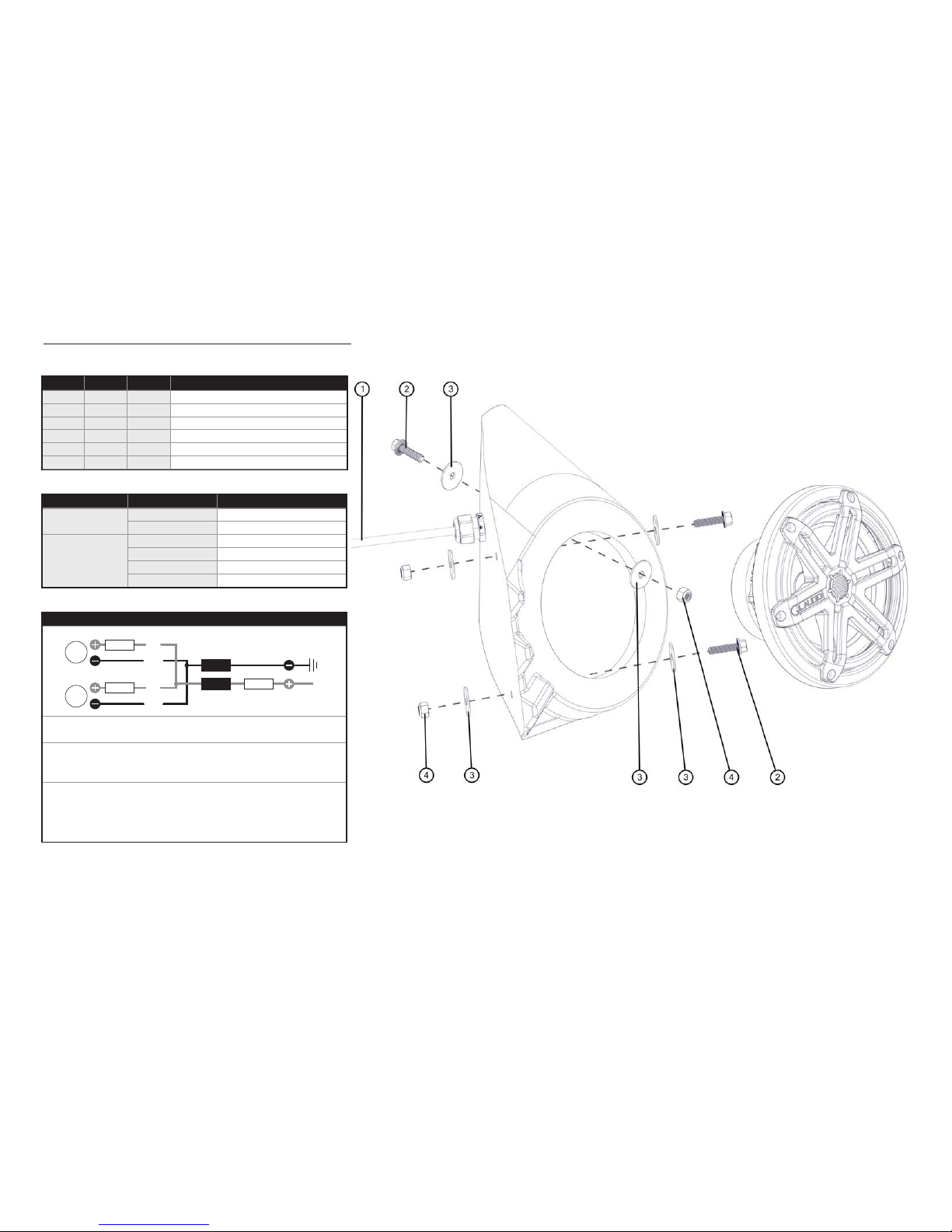
INCLUDED HARDWARE / WIRING INFORMATION
Continued on Next Page
Page 2 • JL Audio, Inc., 2017
SB-POL-GNRLSPKR/MX650 INSTR_SKU# 011502
Note: For optimum p erformance, JL Audio recomme nds applying the included Foa m Strips (or sound damping material) to surro unding plastic panels to redu ce unwanted vibrations.
(hardware pictured for one)
Wire Size Wire Color Use
16 AWG
Red/Stripe Speaker Positive (+)
Black/Stripe
Speaker Negative (-)
20 AWG
Red Not Used
Green Not Used
Blue LED Positive (+)
Yellow LED Negative (-)
BOM ID Qty SKU Description
1 2 152414 Wire Harness (10’)
2 2 153729
1/4 - 20 x 1” Serrated Flange Head Bolt
3 2 153817 1/4” Stainless Steel Flat Washer
4 2 153815 1/4 - 20 Nylon Insert Locknut
- 1 150778 Fuse & Fuse Holder Kit (not shown)
- 1 150249 Foam Tape (not shown)
LED Wire Connections
• For short-circuit protection, install a supplied fuse holder onto EACH
speaker’s BLUE (+12V) LED power connection lead.
• Connect all BLUE (+12V) leads together (parallel) and connect to a
switched +12V supply. Connect all YELLOW (GRD) leads together and
connect to a negative ground or to the NEGATIVE battery post.
• We recommend activating the speakers’ LEDs thru a lighting circuit that
supplies +12V via an existing switch. If an existing switched circuit is
not available, you may install a dedicated toggle/rocker style switch that
will supply positive (+12V) power. Fuse this connection according to how
many LED circuits you have (LED circuits x 150A).
[GND]
LED
[+12V]
Blue
Yellow
Blue
Yellow
Blue
Yellow
Blue
Yellow
LED
Fuse
Fuse
Fuse
Diagram shows one speaker pair of
LED circuits connected in parallel.
 Loading...