

JL Audio Stealthbox SB-B-7SER/10W6v2 Installation Manual

I N S T A L L A T I O N G U I D E
for th e
SB-B-7SER/10W6v2
SKU#94488
2002-2008
Thank you for choosing a JL Audio Stealthbox® for your automotive sound system. With proper
installation, your new vehicle-specific enclosed subwoofer system will deliver years of listening pleasure.
We strongly recommend that you have your new Stealthbox® installed by your authorized JL Audio
dealer. The installation professionals employed by your dealer have the necessary tools and experience
to disassemble and reassemble your vehicle properly. Also, keep in mind that your warranty coverage
extends to 2 years if your system is installed or approved by your authorized JL Audio dealer. If you
prefer to perform your own installation, please read this installation guide completely
before beginning the process.
If you choose to perform the installation yourself, it is absolutely vital that
the Stealthbox
®
be properly mounted to the vehicle according to these
instructions. Failure to mount the enclosure properly presents two problems:
1) The sub-bass performance will suffer due to the movement of the enclosure
caused by the force exerted by the woofer(s).
2) A loose enclosure presents a serious safety hazard in the event of a collision
or sudden deceleration.
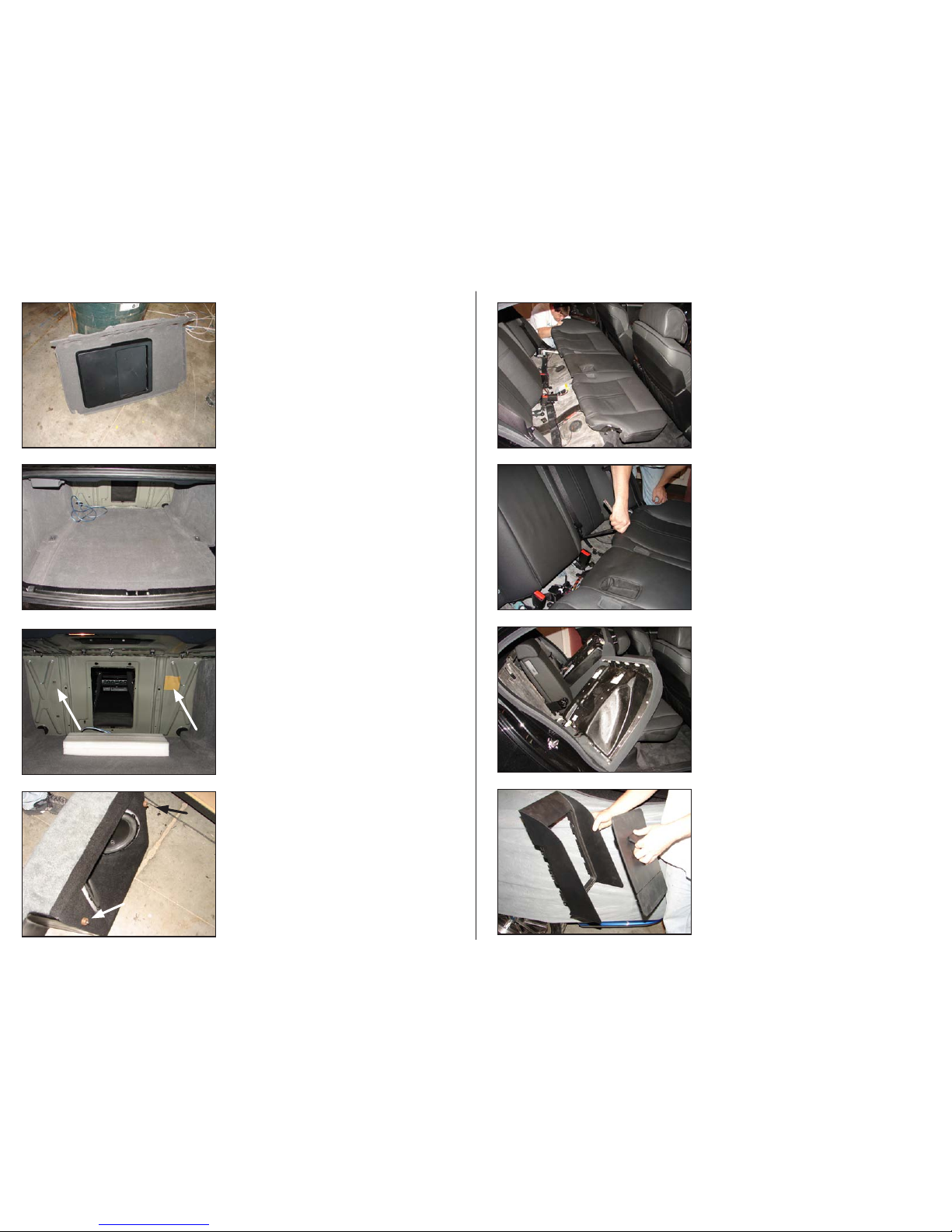
S T E P 1
Empty out the trunk of the car so that you have a clean area
to work in.
Continued on Next Page
S T E P 2
Remove the floor of the trunk compartment and, the rear
bottom cap of the trunk opening as shown.
S T E P 3
Remove the Drivers side trunk liner as shown.
SB-B-7SER/10W6v2 INSTR_SKU# 011311
INS TALLATIO N
D I F F I C U LT Y :
25
OU T
OF
EST IMATED TIME:
1 H OUR
Continued on Next Page
SB-B-7SER/10W6v2 INSTR_SKU# 011311
S T E P 7
Install the two Allen Head Studs with Spacers (included) into
the threaded bosses as shown leaving approximately 1/2” of
the Allen Head Studs exposed.
S T E P 6
View the OEM hole that the arrow on the left is pointing to,
place the wax square on the right in approximately the same
location on the right side as indicated by the arrow. Place the
three 2”x2”x13” Foam Support Blocks in front of the armrest
opening as shown.
S T E P 5
Re-assemble the parts that have been removed from the car.
S T E P 4
Remove the rear seat back panel and set aside. This panel
will not be used.
Page 2 • JL Audio, Inc 2010
S T E P 9
The rear seat back cusion is secured at the bottom by a
number of bolts along the bottom edge, locate them and
remove them so that the back cusion can be lifted up and
forward from it’s anchor points.
S T E P 1 1
Remove the rear armrest trim panel and door remove the
door from the assembly and re-install the trim piece without
the door.
S T E P 1 0
Tilt the rear seat back cusion forward (or remove it entirely).
S T E P 8
Remove the bottom cusion of the back seat, it can be just
slid forward and remain in the vehicle if so desired.
 Loading...