

JL Audio Slash v2 450/4V2, 450/4v2 Owner's Manual
Thank you for purchasing a JL Audio amplifier for
your automotive sound system.
Your amplifier has been designed and manufactured to exacting
standards in order to ensure years of musical enjoyment in your vehicle.
For maximum performance and extended warranty
coverage, we highly recommend that you have your new amplifier
installed by an authorized JL Audio dealer. Your authorized
dealer has the training, expertise and installation equipment to ensure
optimum performance from this product. Should you
decide to install the amplifier yourself, please take the time
to read this manual thoroughly so as to familiarize yourself
with its installation requirements and setup procedures.
If you have any questions regarding the instructions in this
manual or any aspect of your amplifier’s operation, please contact your
authorized JL Audio dealer for assistance. If you need further assistance,
please call the JL Audio Technical Support Department
at (954) 443-1100 during business hours.
OWNER’S MANUAL
four-channel system amplifier
2 | JL Audio - 450/4v2 Owner’s Manual
3
Cooling Efficiency Consid erations:
Your JL Audio amplifier employs an
advanced type of heat management, cal led
RealSink™. This feature takes advantage of
convection and radiation effects to remove
heat from the amplifie r circuitry. For opt imum
cooling performance, the vertical heat sinks
located at the back of the amplifier shou ld be
exposed to as large a volume of air as possible.
Enclosing the amplifier in a small, poorly
ventilated chamber can lead to excessive heat
build-up a nd degraded per formance. If a n
insta llation cal ls for an enclosure around the
amplif ier, we recommend that this enclosure
be ventil ated with the aid of a fan. I n normal
applications, fan-cooling is not necessary, but
you sti ll need to follow s ome basic guidel ines:
• Amplifier mounted vertically with heat sink fins
pointing up: Optimum
• Amplifier mounted horizontally,
right side up: Good
• Amplifier mounted horizontally, but upside
down: Fair (not recommended if there is
less than 1 inch (2.5 cm) clearance above the
amplif ier heat sinks)
• Amplifier mounted vertically with heat sink fins
pointing lateral ly: Fair
• Amplifier mounted vertically with heat sink fins
pointing down: Poor (not recommende d)
If mounting the amplifier under a seat,
make su re there is at lea st 1 inch (2.5 c m) of
space above the amplif ier’s outer shel l to permit
proper coolin g.
Safety Considerations:
Your amplifier needs to be installed in a dry,
well-ventila ted environment a nd in a manner
which does not interfere with your vehicle’s safety
equipment (air bags, seat belt systems, ABS brake
systems, etc.). You should also take the time to
securely mount the ampli fier using appropr iate
hardware so that it does not come loose in t he
event of a co llision or a sudden jolt to the vehicle.
Stupid Mistakes to Avoid:
• Check before drilling any holes in your vehicle
to make sure that you will not be drilling
throug h a gas tank , brake line, wiring har ness or
other v ital vehicle sys tem.
• Do not run system wiring outside or underneath
the vehic le. This is a n extremely da ngerous
practice which can result in severe damage to
your vehic le and person.
• Protect all system wires from sharp metal
edges and wear by carefully routing them,
tying them down and using grommets and
loom where appropriate .
• Do not mount the amplifier in the engine
compart ment, under the ve hicle, on the roof
or in a ny other area th at will exp ose the
amplifier circuitry to the elements.
PROTECT YOUR H EARING!
We value you as a long-term customer. For
that rea son, we urge you to pr actice restra int in
the oper ation of this produc t so as not to d amage
your hearing and that of others in your vehicle.
Studies have shown that cont inuous exposure to
high sound pressure levels can lead to permanent
(irrepara ble) hearing loss . This and a ll other
high-power a mplifiers ar e capable of producing
such hig h sound pressure le vels when connect ed
to a spea ker system. Plea se limit your continuous
exposu re to high volume le vels.
While driving, operate your audio system in
a manner that stil l allows you to he ar necessar y
noises to operate your vehicle safely (horns,
sirens, etc.).
SERIAL NUMBER
In the event that your a mplifier requi res
serv ice or is ever stolen, you will nee d to
have a record of the product’s serial number.
Please take the time to enter that number in
the space provided below. The serial number
can be found on the bot tom panel of the
amplif ier and on the amplifier pac kaging.
Serial Number:
INSTALLATION APPLICATIONS
This amplifier is designed for operation in
vehicles with 12V, negative-ground electrical
systems. Use of this product in vehicles with
positive ground and/or voltages other than 12V
may result in damage to the product and will void
th e w arr ant y.
This product is not certified or approved for
use in aircraft.
Do not att empt to “bridge” t he outputs of th is
amplif ier with the outputs of a second amplifier,
includin g an identical one.
PLANNING YOUR INSTALLATION
It is important that you take the time to read
this m anual and t hat you plan out your
insta llation caref ully. The followi ng are some
considerat ions that you must t ake into account
when plan ning your ins tallation.
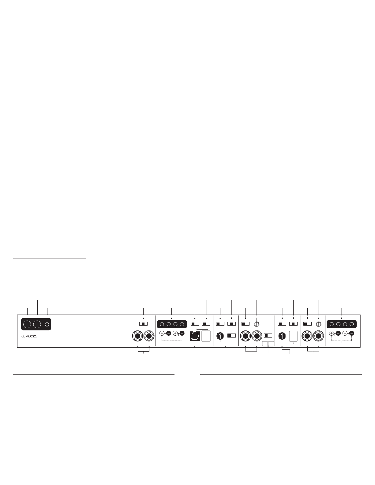
+12VDC Ground Remote CH 1 & 2 Filter SectionCH 1 & 2 Bass Control CH 3 & 4 Filter SectionCH 1 & 2 Input Section CH 3 & 4 Input Section CH 3 & 4 Speak er Outputs
Left Output Right Output HP Filter Freq. (Hz)
Remote
Bass Port
CH 3
(Left)
CH 4
(Right)
CH 1
(Left)
CH 2
(Right)
Freq. Range
Input Voltage Input Sens.Input Sens.
Input Mode
2ch | 4ch
Filter Type
LP | BP | HP
x1 | x10Low | High
Input Voltage
Low | High
High-Pass Filter
Off | 12dB | 24dB
Freq. Range
Filter M ode | Slope
x1 | x10 Off | 12dB | 24dB
Infrasonic Filter
Off | 30Hz
Bass EQ
Off | On
Signal From
1 & 2 | 3 & 4 | All
50
60
7595130
200
50050
60
7595130
200
500
Filter Freq. (Hz)
450/4v2
Four-Channel System Amplifier
Preamp Output Section
1 & 2
Inputs
Only
Either
feature
sums the
CH 1&2 input
signals to
mono when
activated.
1 & 2
and
3 & 4
Bridged: 150W x 1 (3-8Ω)
Left Right
75W
(1.5-4Ω)
75W
Bridged: 300W x 1 (3-8Ω)
Left Right
150W
(1.5-4Ω)
150W
CH 1 & 2 Speak er Outputs
Also sets
low-pass
cutoff for
CH 1 & 2
Bandpass
Filter
(if selected)
CH 1&2
Filter Slope
Selection / Defeat
(pg. 9)
Infrasonic Filter
On/O Switch
(pg. 11)
Preamp Output
Signal Selector
(pg. 10)
Left and Right
Preamp Output Jacks
(pg. 10)
Jack for
Remote Bass
Control Knob
(pg. 11)
CH 3&4
Input Voltage
Range Selector
(pg. 7)
Selects
2ch / 4ch
Input Mode
(pg. 7)
CH 3&4
HP Filter Slope
Selection / Defeat
(pg. 9)
CH 3&4
Filter Frequency
Range Selector
(pg. 9)
Selects CH 3&4
High-Pass Cuto
Frequency and Low-Pass
Cuto for CH 1&2 Bandpass
Filter
(pg. 10)
CH 3&4
Input Sensitivity
Control
(pg. 8)
CH 1&2
Left and Right
Input Jacks
(pg. 7)
CH 3&4
Left and Right
Input Jacks
(pg. 7)
Bass EQ
On/O Switch
(pg. 11)
CH 1&2
Filter Frequency
Range Selector
(pg. 9)
CH 1&2
Input Voltage
Range Selector
(pg. 7)
Remote Turn-On
Connector
(pg. 7)
Chassis Ground
Connector
(pg. 6)
+12 V Power
Connector
(pg. 6)
CH 1&2
Speaker Outputs
(pg. 11)
Selects CH 1&2
HP or LP Cuto
Frequency or HP Cuto
of Bandpass Filter
(pg. 8)
CH 3&4
Speaker Outputs
(pg. 11)
CH 1&2 Input
Sensitivity Control
(pg. 8)

4 | JL Audio - 450/4v2 Owner’s Manual
5
TYPICAL INSTALLATION SEQUENCE
The following represents the sequence for
a typical amplifier installation, using an
after market source u nit or OEM Interfa ce
processor (like the CleanSweep® CL441dsp).
Additional steps and different procedures may
be required in some applications. If you have
any questions, please contact your authorized
JL Audio dea ler for assista nce.
1) Disc onnect the negat ive battery post
connection and secure the disconnected cable
to prevent accidental re-connection during
insta llation. This step is not optional!
2) Ru n power wire (mini mum 4 AWG)
from the battery location to the amplifier
mounting location, taking care to
route it in such a way that it will not be
damage d and will not interfere with
vehicle oper ation. Use 2 AWG or 1/0
AWG power w ire if additiona l amplifiers
are being installed with the 450/4v2.
3) Con nect power wire t o the positive bat tery
post. Fuse the wire with an appropriate fuse
block (and con nectors) within 18 inches (45
cm) wire length of the positive battery post.
This f use is essenti al to protect t he vehicle.
Do not install the fuse until the power wire
has been connected to the amplifier.
4) Run signal cables (RCA cables) and remote
turn-on wire from the source unit to the
amplifier mounting location.
5) Run speaker wire from the speaker systems to
the ampl ifier mounti ng location.
6) Find a good, solid metal grounding point
close to t he amplifier and connect t he
negative power wire to it usi ng appropriate
hardware. Use minimum 4 AWG power wire,
no longer than 36 inches (90 cm) from the
amplifier to the ground connection point. In
some vehicles, it may be necessary to upgrade
the bat tery ground w ire. (See page 6 for
importa nt notice).
7) S ecurely mount t he amplifier u sing
appropriate hardware.
8) Connect the positive and negative power
wires to the amplifier. A fuse near the
amplif ier is not necess ary.
9) Con nect the remote t urn-on wire
to the a mplifier.
10) Connect the RCA input cable s
to the a mplifier.
11) Connect th e speaker wi res to the ampli fier.
12) Carefully review the amplifier’s control
settings to make sure that they are set
according to the needs of the system.
13) Install power wire fuse (60A for a
single 450/4v2) and reconnect the negative
battery post terminal.
14) Turn on the sou rce unit at a low leve l
to double-check that the amplifier is
config ured correct ly. Resist t he temptation
to crank it up until you have verified the
control set tings.
15) Make ne cessary adjus tments to the i nput
sensitivity controls to obtain the right
overall output and the de sired balance
in the system. See Appe ndix B (page 22)
for the recommended input sensitivity
setting method.
16) Enjoy the fruits of your labor with your
favorite music .
PRODUCT DESCRIPTION
The JL Audio 450/4v2 is a four-channel system
amplifier utilizing patented Absolute Symmetry™
Class AB technology for all channels. All
channels benefit from JL Audio’s exclusive R.I.P.S.
power supply de sign which opti mizes the out put
of each ch annel pair for any impedance between
1.5 and 4 ohms per chann el.
The sta ggered power dist ribution of the 1&2
and 3&4 cha nnel pairs (150W x 2 for CH 1&2 and
75 x 2 for CH 3&4) allows for a wide variety of
application options. The 450/4v2 can be operated
in the following modes:
1) As a fu ll-system ampl ifier in bi-amp mode with
CH 1&2 driving subwoofers in low-pass mode
(150W x 1 or 300W x 1) and CH 3&4 driving
main speakers in high-pass mode (75W x 2).
2) As a high power four-channel satellite
amplif ier in a bi-ampli fied system, delivering
high-passed signals to front and rear speaker
systems . In this mode , we recommend that CH
1&2 drive the front speaker systems and CH
3&4 drive the rear speaker systems. Preamp
outputs per mit connection of a separate
amplif ier to drive t he subwoofer system.
3) As a high power four-channel satellite
amplifier in a tri-amplified system,
delivering band-passed signals through
CH 1&2 to mid- bass speakers and highpassed signals throu gh CH 3&4 to midrange/ tweeter speaker systems. Preamp
outputs per mit connection of a separate
amplif ier to drive t he subwoofer system.
4) As a high power three-channel satellite
amplif ier, delivering 150W x 3 at 4Ω in highpass mode to left, center and right spea ker
systems . This require s bridging the outputs of
CH 3&4 to create an equal power third channel
to complement CH 1& 2. Preamp output s
permit connection of a separate amplifier to
drive t he subwoofer system.
The 450/4v2’s f lexible input and crossover
sections permit operation with a wide variety
of source u nits and sys tem configur ations. The
450/4v2 can operate with a single pair of stereo
inputs or with separate inputs for CH 1&2 and
CH 3&4, i f the source un it is equipped w ith front
and rear outputs. The 450/4v2’s preamp output
can send pass-through signals from the CH 1&2
inputs only or the CH 3&4 inputs only or it can
sum all four input channels to feed a subwoofer
amplif ier. This latter mode allows for non-fad ing
sub-bass with front to re ar satellite fa ding.
As we said, it’s very flexible.
6 | JL Audio - 450/4v2 Owner’s Manual
7
TURNON LEAD
The 450/4v2 u ses a conventional +12V remote
turn-on lead, typically controlled by the source
unit’s remote turn-on output. The amplifier will
turn on when +12V is prese nt at its “ Remote”
input and turn off when +12V is switched off. If
a source u nit does not have a dedicated remote
turn-on output, the amplifier’s turn-on lead can
be connec ted to +12V via a switch that derives
power from an ignition-switched circuit.
The 450/4v2’s “Remote” turn-on connector
is designed to accept 18 AWG – 8 AWG wire. 12
AWG is more t han adequate for this purpos e.
To connect the remote turn-on wire to the
amplifier, first back out the set screw on the top
of the amplifier, using the supplied hex wrench.
Strip 1/2 inch (12mm) of wire and insert the
bare wire into the receptacle on the front panel
of the amplifier, seating it firmly so that no bare
wire is exposed. When using smaller wire, it may
be necessary to strip 1 inch of insulation from
the wire and fold the bare wire in half prior to
insertion. While holding the wire in the terminal,
tighten the set screw firmly, taking care not to
strip the head of the screw and making sure that
the wi re is firm ly gripped by t he set screw.
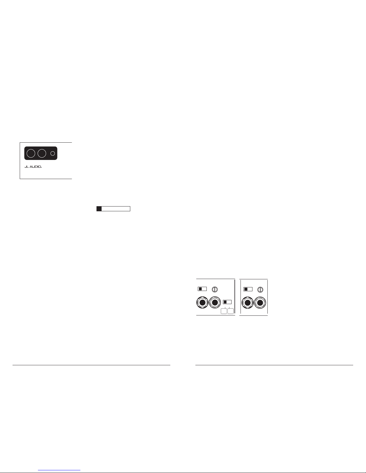
CH 1&2 / CH 3& 4 INPUT SECTION S
The 450/4v2 h as two separa te input sections ,
one for CH 1&2 and another for CH 3&4. Each
section contains a pai r of RCA-type i nput jacks,
an “Input Voltage ” switch and a n “Input Sens.”
rotary control.
CH 3
(Left)
CH 4
(Right)
CH 1
(Left)
CH 2
(Right)
Freq. Range
Input Voltage Input Sens.Input Sens.
Input Mode
2ch | 4ch
x1 | x10 Low | High
Input Voltage
Low | High
High-Pass Filter
Off | 12dB | 24dB
50
60
7595130
200
50050
1 & 2
Inputs
Only
1 & 2
and
3 & 4
Bridged: 150W x 1 (3-8Ω)
Left Right
75W
(1.5-4Ω)
75W
Also sets
low-pass
cutoff for
CH 1 & 2
Bandpass
Filter
(if selected)
CH 3
(Left)
CH 4
(Right)
Input Voltage Input Sens.Input Sens.
|
High
Bridged: 150W x 1 (3-8Ω)
Left Right
75W
(1.5-4Ω)
75W
The “CH 1&2 Input Section” also contains
an “Input M ode” switch to allow operation of
all fou r amplifier c hannels wit h one or two pair s
of input sig nals.
1) Input Mode Switch: If you wish to operate all
four channels of the 450/4v2 with a single pair
of stereo inputs, select the “2ch” position on
the “Input Mode” switch a nd connect a sing le
pair of input cables to th e input jacks in the
“CH 1&2 Input Se ction”. In this mode, the
amplifier will route the signals connected to
the CH 1&2 inputs to CH 3&4 as wel l.
If you wish to use separate inputs for CH 1&2
and CH 3&4 (to allow front-to-rear fading, for
example) and the source unit is equipped with
front and rear outputs, sel ect “4ch” on the “Input
Mode” sw itch located in t he “CH 1&2 Input
Section”. In this mode, you must connect separate
pairs of input cables to ea ch input section.
2) Input Voltage Ra nge: A wide ran ge of signal
input voltages can be accommodated by each
of the 450/4v2’s input sections (200mV – 8V).
This wide range is split up into two sub-ranges,
accessible via switches located in each input
section of the amplifier. Be aware that each
input sec tion’s “Input Voltage” switch will
have to be configured, regardless of how many
input cable s are actua lly feeding t he amplifier.
T h e “ Low ” position on eac h “Input Voltage”
switch s elects an input sensitivity r ange
between 200mV and 2V. This means that the
“Input Sens.” rot ary control w ill operate
within that voltage window. If you are using an
aftermarket source unit, with conventional
preamp-level outputs, this is most likely the
position t hat you will use. The “High” position
on each “I nput Vo ltage” switch selects an
input sensitivity range between 800mV and 8V.
This is useful for certain high-output preamp
level signals as well as speaker-level output
from source units and small amplifiers.
To use speaker-level sources, splice the speaker
output wi res of the source unit or smal l
amplif ier onto a pair of RCA plugs for each
input pair or use the JL Audio ECS Speaker
Wire to RCA adaptor (XB-CL RAIC2-SW).
POWER CONNECTIONS
Before installing the amplifier,
disconnect the negative (ground) wire
from the vehicle’s battery. This will prevent
accidental damage to the system, the vehicle
and your body during in stallation.
+12VDC Ground Remote CH 1 & 2 Filter SectionCH 1 & 2 Bass Control CH 3 & 4 Filter SectionCH 1 & 2 Input Section CH 3 & 4 Input Section CH 3 & 4 Speaker Outputs
Left Output Right Output HP Filter Freq. (Hz)
Remote
Bass Port
CH 3
(Left)
CH 4
(Right)
CH 1
(Left)
CH 2
(Right)
Freq. Range
Input Voltage Input Sens.Input Sens.
Input Mode
2ch | 4ch
Filter Type
LP | BP | HP
x1 | x10 Low | High
Input Voltage
Low | High
High-Pass Filter
Off | 12dB | 24dB
Freq. Range
Filter Mode | Slope
x1 | x10 Off | 12dB | 24dB
Infrasonic Filter
Off | 30Hz
Bass EQ
Off | On
Signal From
1 & 2 | 3 & 4 | All
50
60
7595130
200
50050
60
7595130
200
500
Filter Freq. (Hz)
450/4
v2
Four-Channel System Amplifier
Preamp Outp ut Secti on
1 & 2
Inputs
Only
Either
feature
sums the
CH 1&2 input
signals to
mono when
activated.
1 & 2
and
3 & 4
Bridged: 150W x 1 (3-8Ω)
Left Right
75W
(1.5-4Ω)
75W
Bridged: 300W x 1 (3-8Ω)
Left Right
150W
(1.5-4Ω)
150W
CH 1 & 2 Speaker Outputs
Also sets
low-pass
cutoff for
CH 1 & 2
Bandpass
Filter
(if selected)
The 450/4v2’s “+12 V DC ” and “Grou nd”
connect ions are designed to accept 4 AWG power
wire. 4 AWG is the only recommended power
wire size for this amplifier.
If you are installing the 450/4v2 with other
amplif iers and wish to use a single main power
wire, use 2 AWG or 1/0 AWG main power wire
(depending on the overall current demands of
all the amplifiers in the system). This 2 AWG
or 1/0 AWG power wire shou ld terminate i nto
a distribution block mounted as close to the
amplifiers as possible and should connect to the
450/4v2 wit h 4 AWG power wire.
Note: Smaller AWG numbers mean bigger wire
and vice-versa (1/0 AWG is the largest,
2 AWG is smaller, then 4 AWG, then
8 AWG, etc.).
To connect the power wires to the amplifier,
first back out the set screw on the top of the
amplifier, using the supplied 2.5 mm hex wrench.
Strip 1/2 inch (12 mm) of insulation from the
end of each wire and ins ert the bare w ire into
the receptacle on the front panel of the amplifier,
seating it firmly so that no bare wire is exposed.
While holding the wire in place, tighten the set
screw firmly, taking care not to strip the head
of the sc rew.
The ground connection should be made using
the sa me gauge wire as the power connect ion
(4 AWG) and should be kept as short as possible,
while accessing a solid piece of sheet metal in the
vehicle. T he surface of t he sheet metal should
be sande d at the contact point to create a cle an,
metal-to-metal connection between the chassis
and the termination of the ground wire. For
optimal g rounding, we recommend the u se
of a JL Audio ECS master ground lug
(XB-MGLU). Alternatively, a sheet metal
screw or bolt can be used with a star washer.
Any wires run through metal barriers (such
as firewalls), must be protected with a high
quality insulating grommet to prevent damage
to the insulation of the wire. Failure to do so
may result in a dangerous short circuit.
IMPORTANT
!
Many vehicles employ small (10 AWG - 6 AWG)
wire to ground the battery to the vehicle chassis
and to connect the alternator’s positive
connection to the battery. To prevent voltage
drops, these wires should be upgraded to 4
AWG when installing a mplifier systems with
main f use ratings above 60A.
Fuse Requirements
It is absolutely vital that the main power
wire(s) to the amplifier(s) in the system be
fused within 18 inche s (45 cm) of t he positive
battery post connection. The fuse value at each
power wire should be high enough for all of the
equipment being run from that power wire. If
only the 450/4v2 is being run from that power
wire, we recommend a 60A fuse be used. AGU
(big glass fuse) or MaxiFuse™ (big plastic-body
fuse) ty pes are recom mended.
No fuse is required or rec ommended direct ly
before the amplifier power connection. If one is
desired, we recommend the use of a 60A AGU
fuse or MaxiFuse™ t ype.
8 | JL Audio - 450/4v2 Owner’s Manual
9
2) “Fi lter Mode/Slope” Control: This switch
allows you to defeat the CH 1&2 f ilter or select
from two filter slopes.
“Off ”: Defeats the filter for CH 1&2 completely,
allow ing the ful l range of frequ encies present
at the inputs to feed that pair of channels.
This is useful for systems utilizing outboard
crossovers or requiring full-range reproduction
from th at pair of chan nels.
“ 12d B”: Conf igures the filter for CH 1&2
to attenuat e frequencies above or below the
selected filter frequency at a rate of 12 dB per
octave (Butterworth alignment).
“ 24dB”: Configures the filter for CH 1&2
to attenuat e frequencies above or below the
selected filter frequency at a rate of 24 dB per
octave (Linkwitz-Riley alignment).
Dependi ng on the speak er system and
the vehic le, different f ilter slopes may b e
required to produce a smooth t ransition
between the sound of di fferent speakers in the
system. Experiment to find the slope which
best matches the acoustic requirements of
the sys tem. The shar per “24dB” setting will
do a better job of protecting small speakers
with limited power handling. The shallower
“12dB” octave setting allows the rear speakers
to reproduce m ore low-frequency content.
3 ) “ Fre q. Range” Cont rol: When throw n to
the right, this switch multiplies the cutoff
frequency selected by the rotary “Filter Freq.
(Hz) ” control by a fac tor of 10. In the “x1”
position, the range of the rotary control is
50 - 50 0 Hz (as marked). In t he “x10”
position, the range of the rotary control is
500 Hz - 5 kHz (5000 Hz).
4) “ Filter Fre q. (Hz)” The filte r frequency
marki ngs surroundi ng this rotar y control
are for reference purposes and are generally
accurate to within 1/3 octave or better. If you
would like to select the filter cutoff frequency
with a higher level of precision, consult the
charts in Appendix A (page 22) of this manual.
CH 3&4 Filter Section:
CH 3
(Left)
CH 4
(Right)
Freq. Range
Input Voltage Input Sens.Input Sens.
|
4ch
x1 | x10 Low | High
High-Pass Filter
Off | 12dB | 24dB
50
60
7595130
200
50050
1 & 2
and
3 & 4
Bridged: 150W x 1 (3-8Ω)
Left Right
75W
(1.5-4Ω)
75W
Also sets
low-pass
cutoff for
CH 1 & 2
Bandpass
Filter
(if selected)
1) “ High -Pass Filter” C ontrol: T his switch a llows
you to defeat the CH 3&4 filter or select from
two di fferent filter s lopes.
“ Off ”: Defeats the filter for CH 3&4 completely,
allow ing the ful l range of frequ encies present
at the inputs to feed that pair of channels.
This is useful for systems utilizing outboard
crossovers or requiring full-range reproduction
from the se channels.
“ 12d B”: Configure s the high-pass filter for CH
3&4 to attenuate frequencies below the selected
filter frequency at a r ate of 12 dB per oc tave
(Butterwor th align ment).
“ 24dB”: Configures the high-pass filter for CH
3&4 to attenuate frequencies below the selected
filter frequency at a r ate of 24 dB per o ctave
(Linkw itz-Riley al ignment).
Depending on the speaker system and the
vehicle, different filter slopes may be required to
produce a smooth transition between the speakers
in the system. Exper iment to find t he slope
which best matches the acoustic requirements
of your sy stem. The shar per “24dB” setti ng
will do a better job of protecting sma ll speakers
with limited power handling. The shallower
“12dB” octave setting allows the rear speakers to
reproduce more low-frequency content.
2 ) “Freq. Ra nge” Control: W hen thrown to t he
right, this switch multiplies the cutoff frequency
selected by the rotary “Filter Freq . (Hz)”
control by a factor of 10. In the “x1” position,
the range of the rotary control is 50 - 500 Hz (as
marked). In the “x10” position, the range of the
rotary control is 500 Hz - 5 kHz (5000 Hz).
IMPORTANT
!
The output of the amplifier will decrea se for
a given input voltage when the “Input
Range” s witch is placed i n the “High”
position. Conversely, the output will be
higher with the switch in the “Low” position.
While this may sound counter-intuitive, it is
correct as described.
3) Input Se nsitivity Adjust ment: Located next
to the “I nput Voltage” switch in each input
section is a rotary c ontrol labeled “Input
Sens.”. Once the appropriate “Input Voltage”
range has been selected, this control can be
used to m atch the source u nit’s output voltage
to the input stage of each pair of amplifier
channel s for maximum clean output. Rota ting
the contr ol clockwise w ill result in higher
sensitivity (louder for a given input voltage).
Rotating the control counter- clockwise w ill
result in lower sensitivity (quieter for a given
input voltage). To properly se t each pair
of amplifier channels for maximum clean
output, please refer to Appendix B (page 22)
in th is manual. A fter using t his procedure,
you can then adjust the re lative level of each
channel pair by adjusting the input sensitivity
downward on either or both channel pairs, if
they require attenuation to achieve the desired
system ba lance. Do not i ncrease the “Input
Sens.” setting for any amplifier in the system
beyond the maximum le vel established du ring
the procedure outlined in Appendix B (page
22). Doing so will result in audible distortion
and possible speaker damage. Be aware that
both “Input Sens.” adjustments will have to b e
made, regardless of how many input cables are
feeding the amplifier. These controls will allow
you to set the appropriate relat ive levels for CH
1&2 relative to CH 3&4 and other amplifier
channel s in the syste m.
CROSSOVER CONTROLS
Crossovers a re groups of indi vidual elect ronic
filters which allow only certain frequency
ranges to pass through them by attenuating
frequencies outside the selected range. These
filters allow the user to specify what frequency
range w ill be sent out of each channel s ection
of the amplifier. This, in turn, allows each
speaker system to only re produce a range of
frequencies it is well-suited for, resulting in
reduced di stortion and i mproved fidelity.
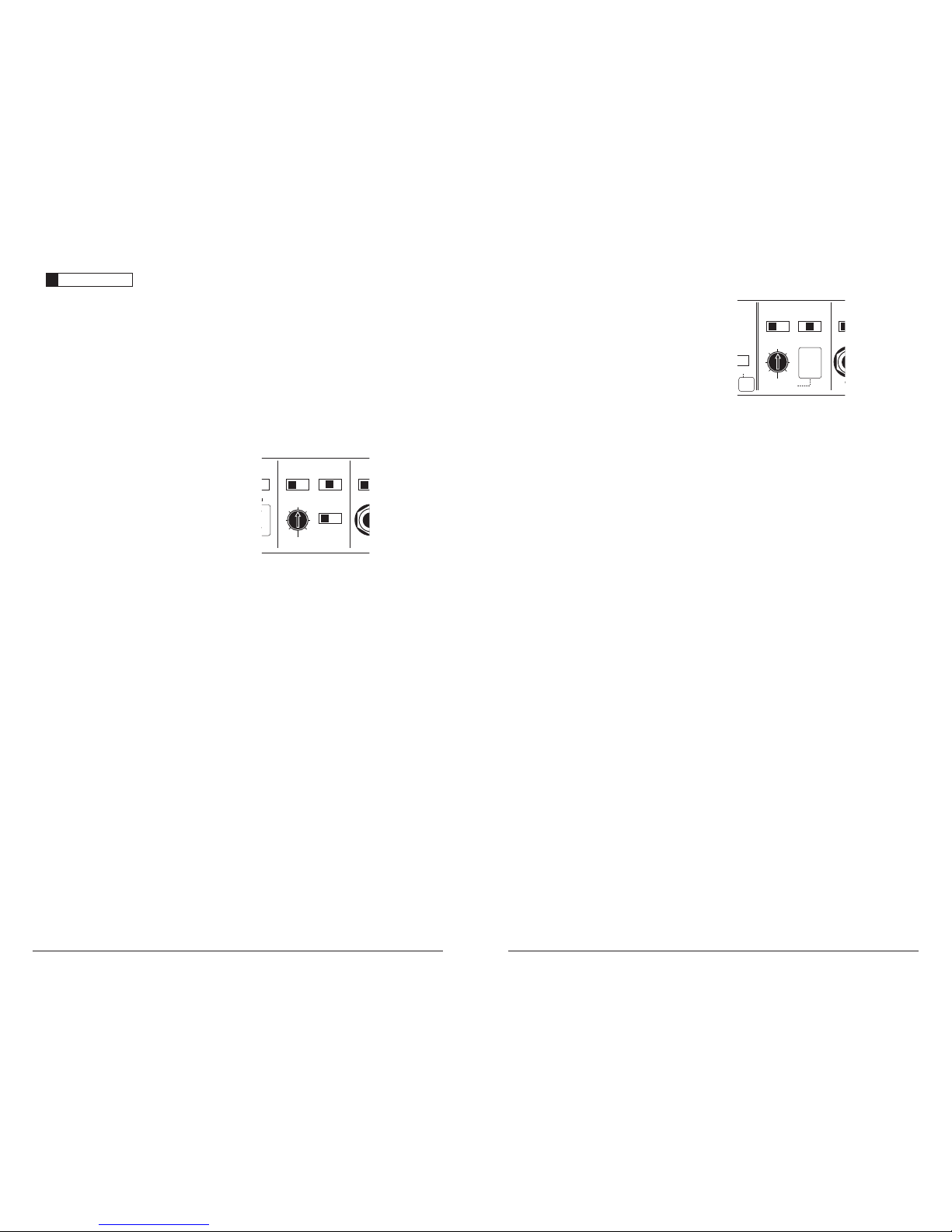
CH 1&2 Filter Section:
CH 3
(Left)
CH 4
(Right)
CH 1
(Left)
CH 2
(Right)
Freq. Range
Input Voltage Input Sens.Input Sens.
Input Mode
2ch | 4ch
Filter Type
LP | BP | HP
x1 | x10 Low | High
Input Voltage
Low | High
High-Pass Filter
Off | 12dB | 24dB
Freq. Range
Filter Mode | Slope
x1 | x10 Off | 12dB | 24dB
50
60
7595130
200
50050
60
7595130
200
500
Filter Freq. (Hz)
1 & 2
Inputs
Only
1 & 2
and
3 & 4
Bridged: 150W x 1 (3-8Ω)
Left Right
75W
(1.5-4Ω)
75W
Also sets
low-pass
cutoff for
CH 1 & 2
Bandpass
Filter
(if selected)
1) “ Filter Ty pe” Control: Lo cated in the
“CH 1&2 Filter Section”, this switch allows
you to conf igure the C H 1&2 fi lter into one
of three filter ty pes:
“ LP” (L ow-Pass): Configures the CH 1&2
filter to attenuate frequencies above
the selected filter frequency. Useful
for connection of subwoofer(s) to CH
1&2 in a bi-a mplified sys tem.
“ BP” (Bandpass): Configures the filter to
attenuate frequencies above the selected filter
frequency and below the frequency selected
in the CH 3&4 High-Pass Filter. This creates
a true bandpass fi lter well-suited for d riving
mid-bass or mid-range spea kers in a tri-
amplified system.
“ HP” (H igh-Pass): Configures the CH 1&2
filter to attenuate freque ncies below the
selected filter frequency. Useful for connection
of component spe akers to CH 1&2 i n a bi-
amplif ied system.
10 | JL Audio - 450/4v2 Owner’s Manual
11
1) “Infr asonic Filter”: The infrasonic f ilter is a
24 dB/octave high-pass fi lter, with a fi xed
cutoff frequency of 30 Hz. This filter is
designed to conserve ampl ifier power and
protect subwoofer systems without audibly
degrading the sub-bass output. With ported
enclosures, the use of the infrasonic filter
is highly recommended to protect the
speaker(s) from excessive excursion below
box tuning. With sealed enclosures, the
use of t he filter is le ss necessar y, but can
still help protect the speaker system. The
infrasonic filter can be completely defeated
by select ing the “Off ” position on the
“Infras onic Filter” switch. This bypasses all
signal from flowing through the circuit.
2) “ Bass EQ”: This switch allows the user to
activate a 6 dB boost centered at 48 Hz.
3) “ Remote Bas s Port”: Allows you to connect an
optional remote boost knob (sold separately,
JL Audio Model RBC-1) that can be mounted
in the front of the vehicle. With the RBC-1
connecte d, the boost i s no longer limited to 0
or +6 dB , allowing a range of 0-15 dB of b oost
to be selected.
IMPORTANT
!
The “Bass EQ” and “Infr asonic Filter” feat ures
will only operate when the CH 1&2 fi lter is
activated and in low-pass mode. If you are
using an external ac tive crossover and would
like to use the “Bass EQ” a nd “Infrasonic
Filter” features, set the “Filter Mode/Slope”
switch on “12dB” and rotate the frequency
selection knob fully clockwise to t he “500 Hz”
position. T his will ac tivate the bass controls
without significantly a ffecting the crossover
point selec ted by the exter nal active cro ssover.
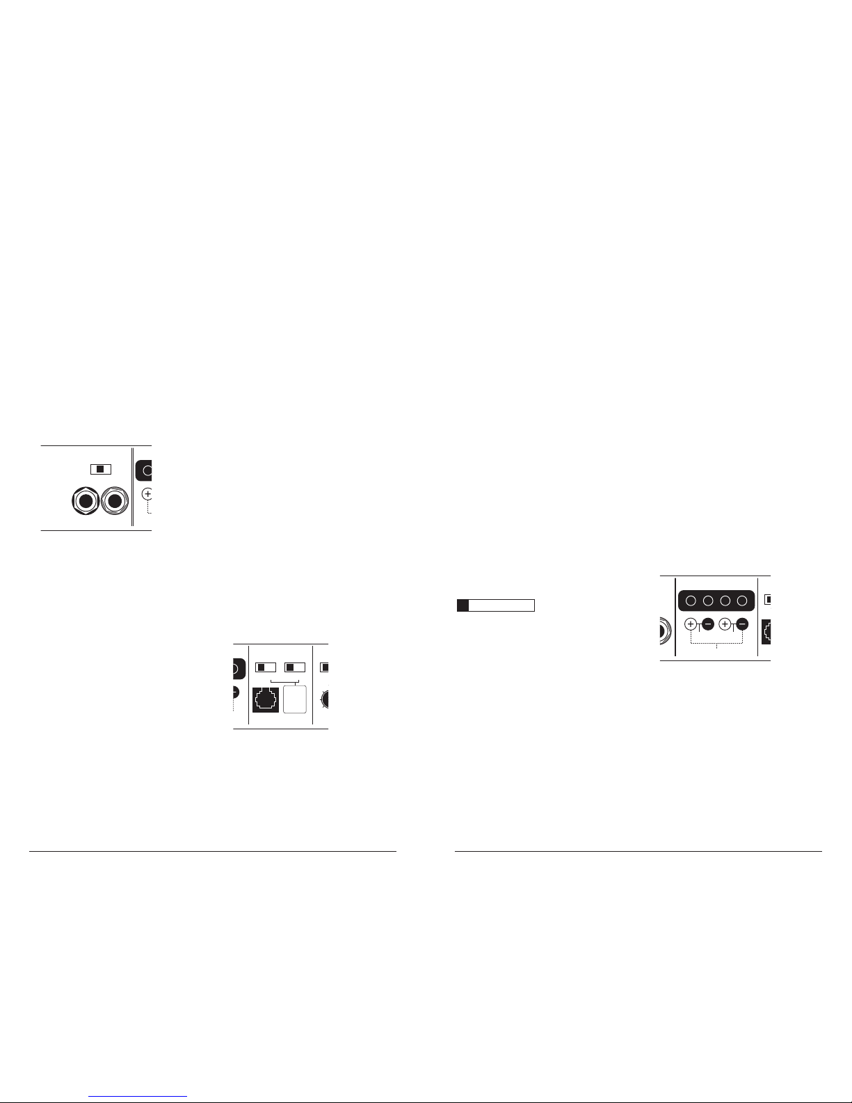
SPEAKER OUTPUTS
The 450/4v2 e mploys JL Audio’s exclusive
Regulated, Intelligent Power Supply (R.I.P.S.)
design. The operation of the R.I.P.S. system is
independent for each pair of c hannels. Thi s
sophisticated power supply allows the amplifier
to produce its optimum power (150 watts x 2 for
channels 1&2 and 75 watts x 2 for channels 3&4)
over a wide range of spea ker impedances .
Unlike conventional ampli fiers that requ ire
a specific impedance to produce optimum
power, the R.I.P.S.-equipped 450/4v2 gives
you the f reedom to use a va riety of spe aker
configurations that achieve final nominal
impedances between 1.5 – 4Ω per channel in
stereo (wit hout sacrifici ng power output or
sound quality). When bridged, each channel
pair will optimize output between 3 – 8Ω.
The operation of the R.I.P.S. circuitry is
entirely automatic and adjusts itself every time
the ampl ifier is tu rned on according to the
lowest impedance present at the speaker load.
There are no user controls to configure. The
system operates through multiple stages of
impedance optimization, choosing the stage
most appropriate to the actual impedance of the
speaker s you connect to it .
Remote
Bass Port
CH 3
(Left)
CH 4
(Right)
CH 1
(Left)
CH 2
(Right)
Freq. Range
Input Voltage Input Sens.Input Sens.
Input Mode
2ch | 4ch
Filter Type
LP | BP | HP
x1 | x10 Low | High
Input Voltage
Low | High
High-Pass Filter
Off | 12dB | 24dB
Freq. Range
Filter Mode | Slope
x1 | x10 Off | 12dB | 24dB
Infrasonic Filter
Off | 30Hz
Bass EQ
Off | On
50
60
7595130
200
50050
60
7595130
200
500
Filter Freq. (Hz)
1 & 2
Inputs
Only
Either
feature
sums the
CH 1&2 input
signals to
mono when
activated.
1 & 2
and
3 & 4
Bridged: 150W x 1 (3-8Ω)
Left Right
75W
(1.5-4Ω)
75W
Bridged: 300W x 1 (3-8Ω)
Left Right
150W
(1.5-4Ω)
150W
CH 1 & 2 Speaker Outputs
Also sets
low-pass
cutoff for
CH 1 & 2
Bandpass
Filter
(if selected)
3) “ Filter Fre q. (Hz)” The filt er frequency
marki ngs surroundi ng this rotar y control
are for reference purposes and are generally
accurate to within 1/3 octave or better. If you
would like to select the filter cutoff frequency
with a higher level of precision, consult the
charts in Appendix A (page 22) of this manual.
Preamp Output Section
The 450/4v2 incorporates a pass-through
preamp output section, so that additional
amplif iers can be ad ded to the syste m. This passthroug h pre-amp output ca n be configu red three
differe nt ways using the switch labeled “Signal
From” in t he “Preamp Output Section”.
Left Output Right Output HP Filter Freq. (Hz)
Remote
Bass Port
CH 3
(Left)
CH 4
(Right)
CH 1
(Left)
CH 2
(Right)
Freq. Range
Input Voltage Input Sens.Input Sens.
Input Mode
2ch | 4ch
Filter Type
LP | BP | HP
x1 | x10 Low | High
Input Voltage
Low | High
High-Pass Filter
Off | 12dB | 24dB
Freq. Range
Filter Mode | Slope
x1 | x10 Off | 12dB | 24dB
Infrasonic Filter
Off | 30Hz
Bass EQ
Off | On
Signal From
1 & 2 | 3 & 4 | All
50
60
7595130
200
50050
60
7595130
200
500
Filter Freq. (Hz)
Preamp Outp ut Secti on
1 & 2
Inputs
Only
Either
feature
sums the
CH 1&2 input
signals to
mono when
activated.
1 & 2
and
3 & 4
Bridged: 150W x 1 (3-8Ω)
Left Right
75W
(1.5-4Ω)
75W
Bridged: 300W x 1 (3-8Ω)
Left Right
150W
(1.5-4Ω)
150W
CH 1 & 2 Speaker Outputs
Also sets
low-pass
cutoff for
CH 1 & 2
Bandpass
Filter
(if selected)
1) “ 1&2 ”: The preamp output delivers the same
signal that is connec ted to the 450/4v2’s
CH 1&2 Inputs. This mode is useful for
feeding a subwoofer amplif ier when the
450/4v2 is being used to drive front and rear
speaker systems. Thi s preamp output mode
will track the signal level of CH 1&2, allowing
fading of the rear channels without affecting
the subwoofer level.
2) “ 3&4”: The preamp out put delivers the s ame
signal that is connected to the 450/4v2’s CH
3&4 Inputs. This mode is useful for feeding a
subwoofer amplifier when the 450/4v2 is being
used to drive front and rear speaker systems.
This preamp output mode will track the signal
level of CH 3&4, allowing fading of the front
channels without affecting the subwoofer level.
3) “ ALL”: This mode del ivers a sum of t he signals
being fed to the “CH 1&2 Input S ection” and
“CH 3&4 Input Se ction” of the amplifier.
The Prea mp Output signa l is not affect ed by
the “LF Boost” or “Inf rasonic Filter” processing
selected for the amplif ier or by any cros sover
filter selected (if the input signal is full-range,
the prea mp output will be full-range). W hen
the 450/4v2 is being used to drive front and
rear speaker systems, this preamp output mode
will deliver a summe d front/rear signa l to the
subwoofer amplifier, while permitting fading
of the f ront and rear spe aker systems f rom the
source u nit.
Note: The s ignal level of t he “Preamp Out put”
is always low level regardless of the voltage
applied to this amplif ier’s inputs and t he
setti ng chosen on th is amplifier’s “Input
Range” switch. A JL Audio amplifier receiving
signal from this preamp output should have
its “Input R ange” switch s et to “Low”.
CH 1 & 2 Bass Control
This section provides two basic bass processing
tools for CH 1&2: a 24 dB/octave infrasonic filter
at 30 Hz and a +6 dB boost circuit centered at 48
Hz. Activation of either feature automatically
sums the CH 1&2 input signals to mono. (These
features should only be used when driving
subwoofer(s) from CH 1&2).
Remote
Bass Port
CH 3
(Left)
CH 4
(Right)
CH 1
(Left)
CH 2
(Right)
Freq. Range
Input Voltage Input Sens.Input Sens.
Input Mode
2ch | 4ch
Filter Type
LP | BP | HP
x1 | x10 Low | High
Input Voltage
Low | High
High-Pass Filter
Off | 12dB | 24dB
Freq. Range
Filter Mode | Slope
x1 | x10 Off | 12dB | 24dB
Infrasonic Filter
Off | 30Hz
Bass EQ
Off | On
50
60
7595130
200
50050
60
7595130
200
500
Filter Freq. (Hz)
1 & 2
Inputs
Only
Either
feature
sums the
CH 1&2 input
signals to
mono when
activated.
1 & 2
and
3 & 4
Bridged: 150W x 1 (3-8Ω)
Left Right
75W
(1.5-4Ω)
75W
Also sets
low-pass
cutoff for
CH 1 & 2
Bandpass
Filter
(if selected)
 Loading...