

JL Audio Slash v2 300/2V2, 300/2v2 Owner's Manual
Thank you for purchasing a JL Audio amplifier for
your automotive sound system.
Your amplifier has been designed and manufactured to exacting
standards in order to ensure years of musical enjoyment in your vehicle.
For maximum performance and extended warranty
coverage, we highly recommend that you have your new amplifier
installed by an authorized JL Audio dealer. Your authorized
dealer has the training, expertise and installation equipment to ensure
optimum performance from this product. Should you
decide to install the amplifier yourself, please take the time
to read this manual thoroughly so as to familiarize yourself
with its installation requirements and setup procedures.
If you have any questions regarding the instructions in this
manual or any aspect of your amplifier’s operation, please contact your
authorized JL Audio dealer for assistance. If you need further assistance,
please call the JL Audio Technical Support Department
at (954) 443-1100 during business hours.
OWNER’S MANUAL
two-channel full-range amplifier
2 | JL Audio - 300/2v2 Owner’s Manual
3
Cooling Efficiency Consid erations:
Your JL Audio amplifier employs an
advanced type of heat management, cal led
RealSink™. This feature takes advantage of
convection and radiation effects to remove
heat from the amplifie r circuitry. For opt imum
cooling performance, the vertical heat sinks
located at the back of the amplifier shou ld be
exposed to as large a volume of air as possible.
Enclosing the amplifier in a small, poorly
ventilated chamber can lead to excessive heat
build-up a nd degraded per formance. If a n
insta llation cal ls for an enclosure around the
amplif ier, we recommend that this enclosure
be ventil ated with the aid of a fan. I n normal
applications, fan-cooling is not necessary, but
you sti ll need to follow s ome basic guidel ines:
• Amplifier mounted vertically with heat sink fins
pointing up: Optimum
• Amplifier mounted horizontally,
right side up: Good
• Amplifier mounted horizontally, but upside
down: Fair (not recommended if there is
less than 1 inch (2.5 cm) clearance above the
amplif ier heat sinks)
• Amplifier mounted vertically with heat sink fins
pointing lateral ly: Fair
• Amplifier mounted vertically with heat sink fins
pointing down: Poor (not recommende d)
If mounting the amplifier under a seat,
make su re there is at lea st 1 inch (2.5 c m) of
space above the amplif ier’s outer shel l to permit
proper coolin g.
Safety Considerations:
Your amplifier needs to be installed in a dry,
well-ventila ted environment a nd in a manner
which does not interfere with your vehicle’s safety
equipment (air bags, seat belt systems, ABS brake
systems, etc.). You should also take the time to
securely mount the ampli fier using appropr iate
hardware so that it does not come loose in t he
event of a co llision or a sudden jolt to the vehicle.
Stupid Mistakes to Avoid:
• Check before drilling any holes in your
vehicle to make sure that you will not be
drilling through a gas tank, brake line, wiring
harnes s or other vita l vehicle system.
• Do not run system wiring outside or underneath
the vehic le. This is a n extremely da ngerous
practice which can result in severe damage to
your vehic le and person.
• Protect all system wires from sharp metal
edges and wear by carefully routing them,
tying them down and using grommets and
loom where appropriate .
• Do not mount the amplifier in the engine
compart ment, under the ve hicle, on the roof
or in a ny other area th at will exp ose the
amplifier circuitry to the elements.
PROTECT YOUR H EARING!
We value you as a long-term customer. For
that rea son, we urge you to pr actice restra int in
the oper ation of this produc t so as not to d amage
your hearing and that of others in your vehicle.
Studies have shown that cont inuous exposure to
high sound pressure levels can lead to permanent
(irrepara ble) hearing loss . This and a ll other
high-power a mplifiers ar e capable of producing
such hig h sound pressure le vels when connect ed
to a spea ker system. Plea se limit your continuous
exposu re to high volume le vels.
While driving, operate your audio system in
a manner that stil l allows you to he ar necessar y
noises to operate your vehicle safely (horns,
sirens, etc.).
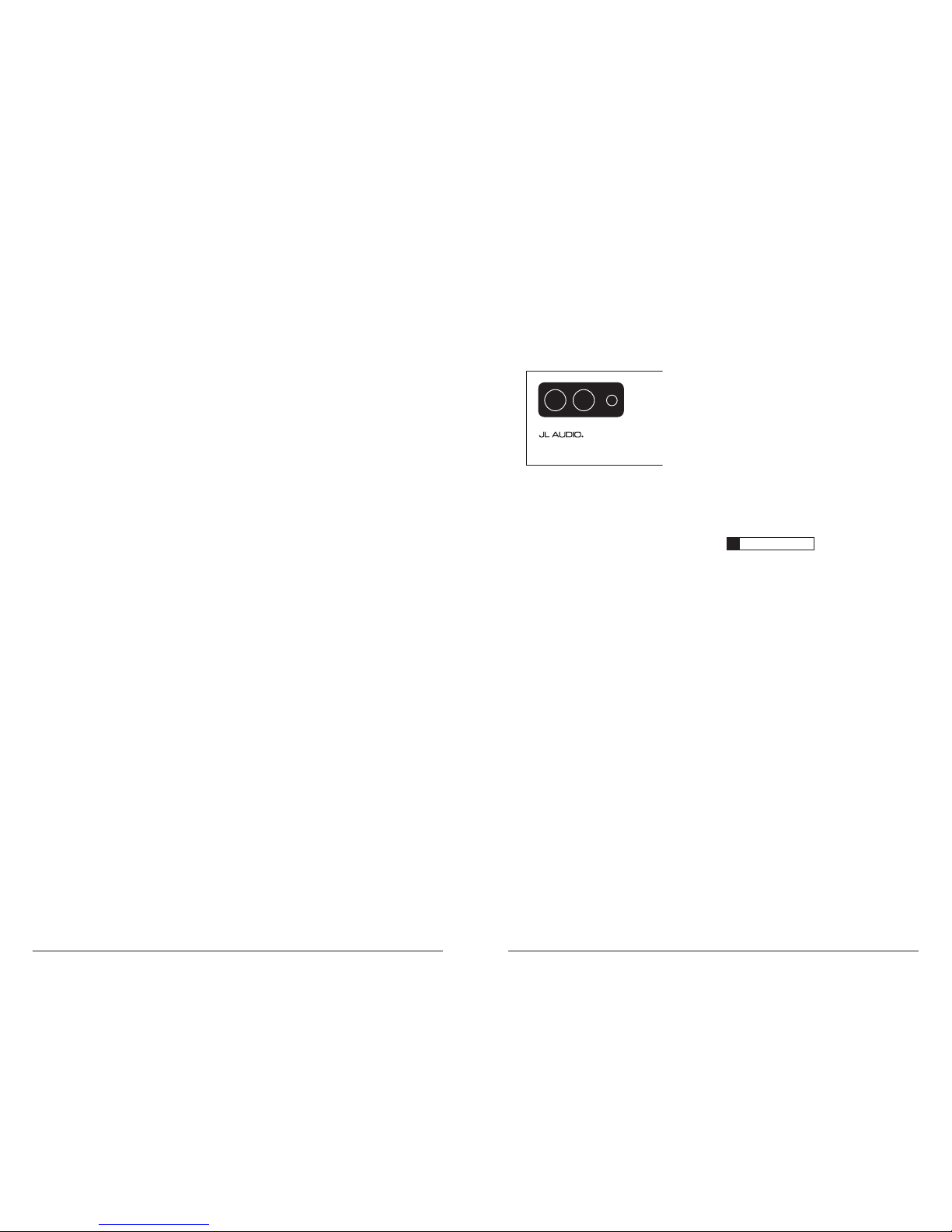
SERIAL NUMBER
In the event that your a mplifier requi res
serv ice or is ever stolen, you will nee d to
have a record of the product’s serial number.
Please take the time to enter that number in
the space provided below. The serial number
can be found on the bot tom panel of the
amplif ier and on the amplifier pac kaging.
Serial Number:
INSTALLATION APPLICATIONS
This amplifier is designed for operation in
vehicles with 12V, negative-ground electrical
systems. Use of this product in vehicles with
positive ground and/or voltages other than 12V
may result in damage to the product and will void
th e w arr ant y.
This product is not certified or approved for
use in aircraft.
Do not att empt to “bridge” t he outputs of th is
amplif ier with the outputs of a second amplifier,
includin g an identical one.
PLANNING YOUR INSTALLATION
It is important that you take the time to read
this m anual and t hat you plan out your
insta llation caref ully. The followi ng are some
considerat ions that you must t ake into account
when plan ning your ins tallation.
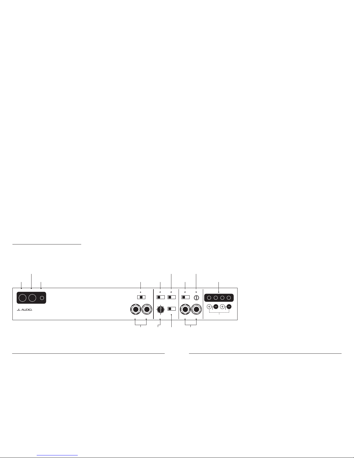
Preamp Output
Signal Selector
(pg. 8)
Input Voltage
Range Selector
(pg. 6)
Filter Slope
Selection
(pg. 7)
Filter Frequency
Range Selector
(pg. 8)
Input Sensitivity
Control
(pg. 7)
Left and Right
Preamp Output Jacks
(pg. 8)
Left and Right
Input Jacks
(pg. 8)
Remote Turn-On
Connector
(pg. 6)
Chassis Ground
Connector
(pg. 5)
+12 V Power
Connector
(pg. 5)
Speaker Outputs
(pg. 9)
Filter
Cuto
Frequency
Selector
(pg. 8)
Filter
Mode
Selector
(pg. 7)
Bridged
Left Right
+12VDC Ground Remote Preamp Output Section Amp Filter Controls Amplifier Input Section
Speaker Outputs
Left Ch. Right Ch.Left Output Right Output Filter Freq. (Hz)
Full Range | Low-Pass | High-Pass
Output Mode Filter SlopeFreq. Range Input Voltage Input Sens.
12dB | 24dB
Filter Mode
Off | LP | HP
x1 | x10 Low | High
50
60
7595130
200
500
300 /2v2
Two-Channel Full-Range Amplifier
4 | JL Audio - 300/2v2 Owner’s Manual
5
POWER CONNECTIONS
Before installing the amplifier,
disconnect the negative (ground) wire
from the vehicle’s battery. This will prevent
accidental damage to the system, the vehicle
and your person during i nstallation.
Bridged
Left Right
+12VDC Ground Remote Preamp Output Section Amp Filter Controls Amplifier Input Section
Speaker Outputs
Left Ch. Right Ch.Left Output Right Output Filter Freq. (Hz)
Full Range | Low-Pass | High-Pass
Output Mode Filter SlopeFreq. Range Input Voltage Input Sens.
12dB | 24dB
Filter Mode
Off | LP | HP
x1 | x10 Low | High
50
60
7595130
200
500
300 /2v2
Two-Channel Full-Range Amplifier
The 30 0/2v2’s “+1 2 VD C” and “Ground”
connections are designed to accept 8 - 4
AWG power w ire. 8 AWG is the minimum
recommended power wire size for this amplifier.
If you are installing the 300/2v2 with other
amplif iers and wish to use a single main power
wire, use 2 AWG or 1/0 AWG main power wire
(depending on the overall current demands of
all the amplifiers in the system). This 2 AWG
or 1/0 AWG power wire shou ld terminate i nto
a distribution block mounted as close to the
amplifiers as possible and should connect to the
300/2v2 with 8 - 4 AWG power wire.
Note: that smaller AWG numbers mean bigger
wire and vice-versa (1/0 AWG is the largest,
2 AWG is smaller, then 4 AWG, then
8 AWG, etc.).
To connect the power wires to the amplifier,
first back out the set screw on the top of the
terminal block, using the supplied 2.5 mm hex
wrench. S trip 1/2 inch (12 mm) of in sulation from
the end of each wire and insert the bare wire into
the terminal block, seating it firmly so that no
bare wire is exposed. While holding the wire in
place, tighten the set screw firmly, taking care not
to strip the head of the screw.
The ground connection should be made using
the sa me gauge wire as t he power connection
and should be kept as short as possible, while
accessing a solid piece of sheet metal in the
vehicle. The surface of the sheet metal should
be sande d at the contact p oint to create a clea n,
metal-to-me tal connection between the chassis
and the termination of t he ground wire. For
optimal g rounding, we recommend the u se of a
JL Audio ECS ma ster ground lug (XB-MGLU).
Alternat ively, a sheet metal screw or bolt can be
used with a star washer.
Any wires run through metal barriers (such as
firewa lls), must be protec ted with a hi gh quality
insulat ing grommet to prevent damage to t he
insulation of the wire. Failure to do so may result
in a dangerous short circuit.
IMPORTANT
!
Many vehicles employ small (10 AWG -
6 AWG) wire to ground the battery to the
vehicle chassis and to connect the alternator’s
positive con nection to the bat tery. To prevent
voltage drops, these wires should be upgr aded
to 4 AWG when installing amplif ier systems
with ma in fuse rati ngs above 60A.
FUSE REQUIREMENTS
It is absolutely vital that the main power
lead to the amplifier(s) in the system be fused
within 18 inches (45 cm) of the positive battery
post connection. The fuse value at each power
wire should be high enough for all of the
equipment being run from that power wire.
If only the 300/2v2 is being run from
that power wire, we recommend a 40A fuse
be used . AGU (big g lass fuse), Max iFuse™
(big plas tic-body fuse) or A FS (miniblade fu se) ty pes are recommende d.
No fuse is required or rec ommended direct ly
before the amplifier power connection. If one is
desired, we recommend the u se of a 40A AGU,
AFS or Ma xiFuse™ t ype fuse.
PRODUCT DESCRIPTION
The JL Aud io 300/2v2 is a two-channel f ull-
range a mplifier uti lizing patented A bsolute
Symmetry™ Class A/B technology for both
channels. These channels benefit from JL Audio’s
exclusive R.I.P.S. power supply design which
optimi zes the output for any impedance between
1.5 and 4 ohms per channel (3 - 8Ω bridged).
The 300/2v2’s flexible input and crossover
sections permit operation with a wide variety of
source u nits and system configurat ions.
TYPICAL INSTALLATION SEQUENCE
The following represents the sequence
for a ty pical amplif ier instal lation, using a n
after market source u nit or OEM Interfa ce
processor (like the CleanSweep® CL441dsp).
Additional steps and different procedures may
be required in some applications. If you have
any questions, please contact your authorized
JL Audio dea ler for assista nce.
1) D isconnect the ne gative battery post
connection and secure the disconnected cable
to prevent accidental re-connection during
insta llation. This step is not optional!
2) Run power wire (minimum 8 AWG) from the
battery location to the amplifier mounting
location, taking ca re to route it in such a
way that it will not be damaged and will not
interfere w ith vehicle oper ation. Use 4 , 2 or
1/0 AWG power wire if additional ampl ifiers
are bei ng installed with the 30 0/2v2.
3) Connect power wire to the positive battery
post. Fuse the wire with an appropriate fuse
block (and con nectors) within 18 inches (45
cm) wire length of the positive battery post.
This f use is essenti al to protect t he vehicle. Do
not install the fuse until the power wire has
been conne cted to the a mplifier.
4) Run signal cables (RCA cables) and remote
turn-on wire from the source unit to the
amplifier mounting location.
5) Run speaker wire from the speaker systems to
the ampl ifier mounti ng location.
6) Find a good, solid metal ground ing point
close to t he amplifier and connect t he
negative power wire to it usi ng appropriate
hardware. Use minimum 8 AWG power wire,
no longer than 36 inches (90 cm) from the
amplifier to the ground connection point. In
some vehicles, it may be necessary to upgrade
the bat tery ground w ire. (See page 5 for
importa nt notice).
7) Securely mount the amplifier using
appropriate hardware.
8) Connect the positive and negative power
wires to the amplifier. A fuse near the
amplif ier is not necess ary.
9) Connect the remote turn-on wire
to the a mplifier.
10) Connect the RCA input cables
to the a mplifier.
11) Conne ct the speak er wires to t he amplifier.
1 2 ) C arefully rev iew the ampli fier’s control
settings to make sure that they are set
according to the needs of the system.
1 3 ) Install power wire fuse (40A for a
single 300/2v2) and reconnect the negative
battery post terminal.
14) Turn on the source un it at a low level
to double-check that the amplifier is
config ured correct ly. Resist t he temptation
to crank it up until you have verified the
control set tings.
15) Make necessary adjustments to the input
sensitivity controls to obtain the right
overall output and the de sired balance
in the system. See Appe ndix A (page 12)
for the recommended input sensitivity
setting method.
1 6 ) Enjoy the fruits of your labor wit h your
favorite music .
6 | JL Audio - 300/2v2 Owner’s Manual
7
IMPORTANT
!
The output of t he amplifier w ill decrease for
a given input voltage when t he “Input Range”
switch is placed in the “H igh” position.
Conversely, the output wil l be higher with
the switch in the “Low” position. Whi le this
may sound counter-intuit ive, it is correc t
as described.
2) Input Se nsitivity Adjust ment: Located next to
the “Input Volt age” switch in the “Amplifier
Input Sec tion” is a rotary control labeled
“Input Sens.”. Once t he appropriate “Input
Vol ta ge ” range has been selecte d, this control
can be used to match the source unit’s output
voltage to the input stage of the 300/2v2 for
maximum clean output. Rotating the control
clockwise will result in higher sensitivity
(louder for a given input voltage). Rotating the
control cou nter-clockwise w ill result in lower
sensitivity (quieter for a given input voltage).
To properly set the amplifier for maximum
clean out put, please refer to Appendix A
(page 12) in this manual. After using this
procedure, you can then adju st the “Input
Sens.” level downward if this is required
to achieve the desired sy stem balance.
Do not inc rease the “Input S ens.” setting
for any a mplifier in t he system beyond
the maximum level established during
the procedure outlined in Appendix A
(page 12). Doing s o will resu lt in audible
distort ion and possible s peaker dama ge.
CROSSOVER CONTROLS
Crossovers are groups of individual electronic
filters which allow only cer tain frequenc y ranges
to pass through them by attenuating frequencies
outside the selec ted range. These fi lters allow t he
user to specify what frequency ra nge will be s ent
to the each a mplifier (or channels) in a system.
This, in turn, al lows each spea ker system to
only reproduce a ra nge of frequencies it is wellsuited for, resu lting in reduce d distortion and
improved fidelity.
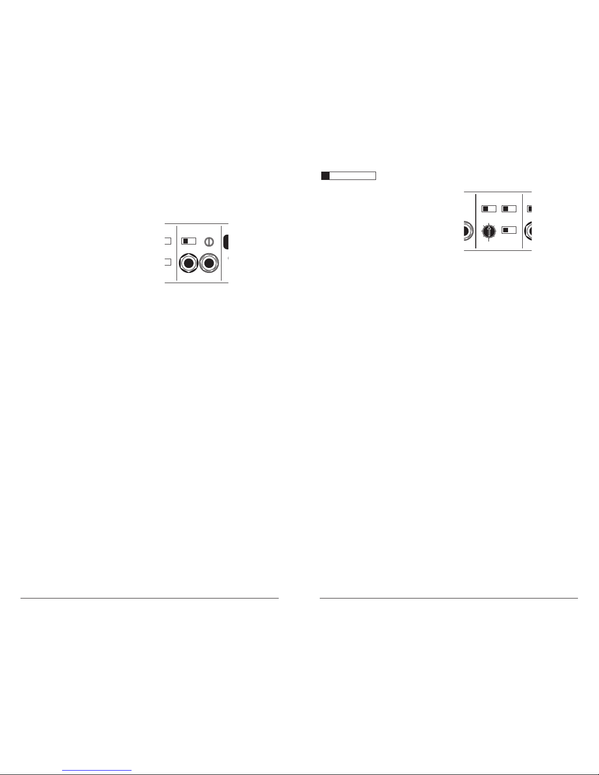
AMPLIFIER FILTER SECTION
Bridged
Left Right
Speaker Outputs
Left Ch. Right Ch.Left Output Right Output Filter Freq. (Hz)
12dB | 24dB
Filter Mode
Off | LP | HP
x1 | x10 Low | High
50
60
7595130
200
500
1) “ Filter M ode” Control: Th is switch al lows you
to conf igure the f ilter into one of t wo filter
type s or to defeat it complet ely:
“ Off ”: Defeats the filter for that channel
section completely, a llowing the full range of
frequencies present at the inputs to feed the
amplifier. This is useful for systems utilizing
outboard c rossovers or requir ing full-ra nge
reproduction from the 300/2 v2.
“ LP” (Low-Pass): Configures the filter to
attenuate frequencies above the selected
filter frequency. Useful for connection of
subwoofer(s) to the 3 00/2v2.
“ HP” (H igh-Pass): Config ures the
filter to attenuate frequencies below
the sele cted filter f requency. Useful for
connect ion of component speake rs to
the 30 0/2v2 in a bi-ampl ified system.
2) “Filter Slop e
” Control: This switch
allows you to select from two filter
slopes for t hat channel sec tion.
“
12dB
”: Config ures the fi lter to attenuate
frequencies above or below the selected
filter frequency at a rate of 12 dB per octave
(Butterwor th alignment).
“
24dB
”: Configures the filter to attenuate
frequencies above or below the selected
filter frequency at a rate of 24 dB p er octave
(Linkw itz-Riley al ignment).
TURNON LEAD
The 30 0/2v2 uses a convent ional +12V remote
turn-on lead, typically controlled by the source
unit’s remote turn-on output. The amplifier will
turn on when +12V is prese nt at its “ Remote”
input and turn off when +12V is switched off. If
a source u nit does not have a dedicated remote
turn-on output, the amplifier’s turn-on lead can
be connec ted to +12V via a switch that derives
power from an ignition-switched circuit.
The 30 0/2v2’s “Remote” turn-on connector is
designed to accept 18 AWG – 8 AWG wire.
12 AWG is more than adequate for this purpose.
To connect the remote turn-on wire to the
amplifier, first back out the set screw on the top
of the amplifier, using the supplied hex wrench.
Strip 1/2 inch (12mm) of wire and insert the
bare wire into the receptacle on the front panel
of the amplifier, seating it firmly so that no bare
wire is exposed. When using smaller wire, it may
be necessary to strip 1 inch of insulation from
the wire and fold the bare wire in half prior to
insertion. While holding the wire in the terminal,
tighten the set screw firmly, taking care not to
strip the head of the screw and making sure that
the wi re is firm ly gripped by t he set screw.
INPUT SECTION
The 30 0/2v2 has one input s ection, which
contains a pair of RCA-ty pe input jacks, an
“Input Voltage” sw itch and an “Input Sens.”
rotary control.
Bridged
Left Right
Speaker Outputs
Left Ch. Right Ch.Left Output Right Output Filter Freq. (Hz)
24dB
|
HP
|
High
1) Input Voltage Ra nge: A wide range of signal
input voltages can be accommodated by
the 300/2v2’s input section (200mV – 8V).
This w ide range is spl it up into two subranges, accessible via a switch located in
the “Amplifi er Input Section”. The “ Low”
position on the “Input Voltage” switch selects
an input sensitivity range between 200mV
and 2V. This mea ns that the “I nput Sens.”
rotary control will operate within that voltage
window. If you are using an aftermarket
source u nit, with convent ional preamp-level
outputs, this is most likely the position that you
will use. The “High ” position on the “I nput
Vol ta ge ” switch selects an input sensitivity
range between 800mV and 8V. This is useful
for certain high-output preamp level signals
as well as speaker-level out put from source
units and small amplifiers. To use speaker-level
sources, splice the speaker output wires of the
source unit or small amplifier onto a pair of
RCA plugs or use the JL Audio ECS Speaker
Wire to RCA adaptor (XB-CL RAIC2-SW).
 Loading...