

JL Audio Slash v2 250/1V2, 250/1v2 Owner's Manual
Thank you for purchasing a JL Audio amplifier for
your automotive sound system.
Your amplifier has been designed and manufactured to exacting
standards in order to ensure years of musical enjoyment in your vehicle.
For maximum performance and extended warranty
coverage, we highly recommend that you have your new amplifier
installed by an authorized JL Audio dealer. Your authorized
dealer has the training, expertise and installation equipment to ensure
optimum performance from this product. Should you
decide to install the amplifier yourself, please take the time
to read this manual thoroughly so as to familiarize yourself
with its installation requirements and setup procedures.
If you have any questions regarding the instructions in this
manual or any aspect of your amplifier’s operation, please contact your
authorized JL Audio dealer for assistance. If you need further assistance,
please call the JL Audio Technical Support Department
at (954) 443-1100 during business hours.
OWNER’S MANUAL
monoblock subwoofer amplifier
2 | JL Audio - 250/1v2 Owner’s Manual
3
PLANNING YOUR INSTALLATION
It is importa nt that you take the time to read
this manual and that you plan out your
installation carefully. The following are some
considerations that you must take into account
when planning your installation.
Cooling Efficiency Considerations:
Your JL Audio amplif ier employs an
advanced type of heat management, called
RealSink™. Th is feature takes adva ntage of
convection a nd radiation effects to remove
heat from the a mplifier circuitr y. For optimum
cooling per formance, the vertical heat sin ks
located at the back of the ampli fier should be
exposed to as large a volume of a ir as possible.
Enclosing the amplifier in a small, poorly
ventilated chamber can le ad to excessive heat
build-up and degraded performance. If an
installation ca lls for an enclosure around the
amplifier, we recommend that this enclosure
be ventilated with the a id of a fan. In normal
applications , fan-cooling is not necessary, but
you still need to follow some basic g uidelines:
• Amplif ier mounted vertically w ith heat sink fins
pointing up: Optimum
• Amplif ier mounted horiz ontally,
right side up: Good
• Amplif ier mounted horiz ontally, but upside
down: Fair (not recommended if there is
less than 1 inch (2.5 cm) clearance above the
amplifier heat sinks)
• Amplif ier mounted vertically w ith heat sink fins
pointing laterally: Fair
• Amplif ier mounted vertically w ith heat sink fins
pointing down: Poor (not recommended)
If mounting t he amplifier under a seat,
make sure t here is at least 1 inch (2.5 cm) of
space above the amplifier’s outer shell to permit
proper cooling.
Safety Considerations:
Your amplifier needs to be insta lled in a dry,
well-ventilated environment and in a man ner
which does not interfere with your vehicle’s safet y
equipment (air bags , seat belt systems, ABS brake
systems, etc.). You should also take the time to
securely mou nt the amplifier using t he supplied
screws so that it does not come loose in the event
of a collision or a sudden jolt to the vehicle.
Stupid Mistakes to Avoid:
• Check before d rilling any holes in you r vehicle
to make sure that you will not be drilling
through a gas tank, brake li ne, wiri ng harness or
other vita l vehicle system.
• Do not run system wiri ng outside or underneath
the vehicle. This is an ex tremely dangerous
practice which can result in severe damage to
your vehicle and person.
• Protect all system wires from sha rp metal
edges and wea r by carefully routing them,
tying them down and using grommets and
loom where appropriate.
• Do not mount the ampl ifier in the engine
compart ment, under the vehicle, on t he roof
or in any other area that will expose the
amplif ier circuitry to the elements.
PROTECT YOUR HEARING !
We value you as a long-term customer. For
that reason, we urge you to practice restraint in
the operation of this product so as not to damage
your hearing and that of others in your vehicle.
Studies have shown that continuous exposure to
high sound pressure levels can lead to permanent
(irreparable) hearing loss. This and al l other
high-power amplifiers a re capable of producing
such high sound pressure levels when connected
to a speaker s ystem. Please limit you r continuous
exposure to high volume levels.
While d riving, operate your aud io system in
a manner that still a llows you to hear necessary
noises to operate you r vehicle safely (horns,
sirens, etc.).
SERIAL NUMBER
In the event that your amplif ier requires
service or is ever stolen, you wi ll need to
have a record of the produc t’s serial nu mber.
Please take the time to enter that number in
the space prov ided below. The serial number
can be found on t he bottom panel of the
amplif ier and on the amplifier packaging.
Serial Number:
INSTALLATION APPLICATIONS
This ampl ifier is designed for operat ion in
vehicles with 12V, negative-ground elec trical
systems. Use of this product in vehicles with
positive ground and/or voltages other than 12V
may result in damage to the product and wi ll void
the warranty.
This product is not certified or approved for
use in aircraft.
Do not attempt to “bridge” the outputs of this
amplif ier with the outputs of a second amplifier,
including an identical one.
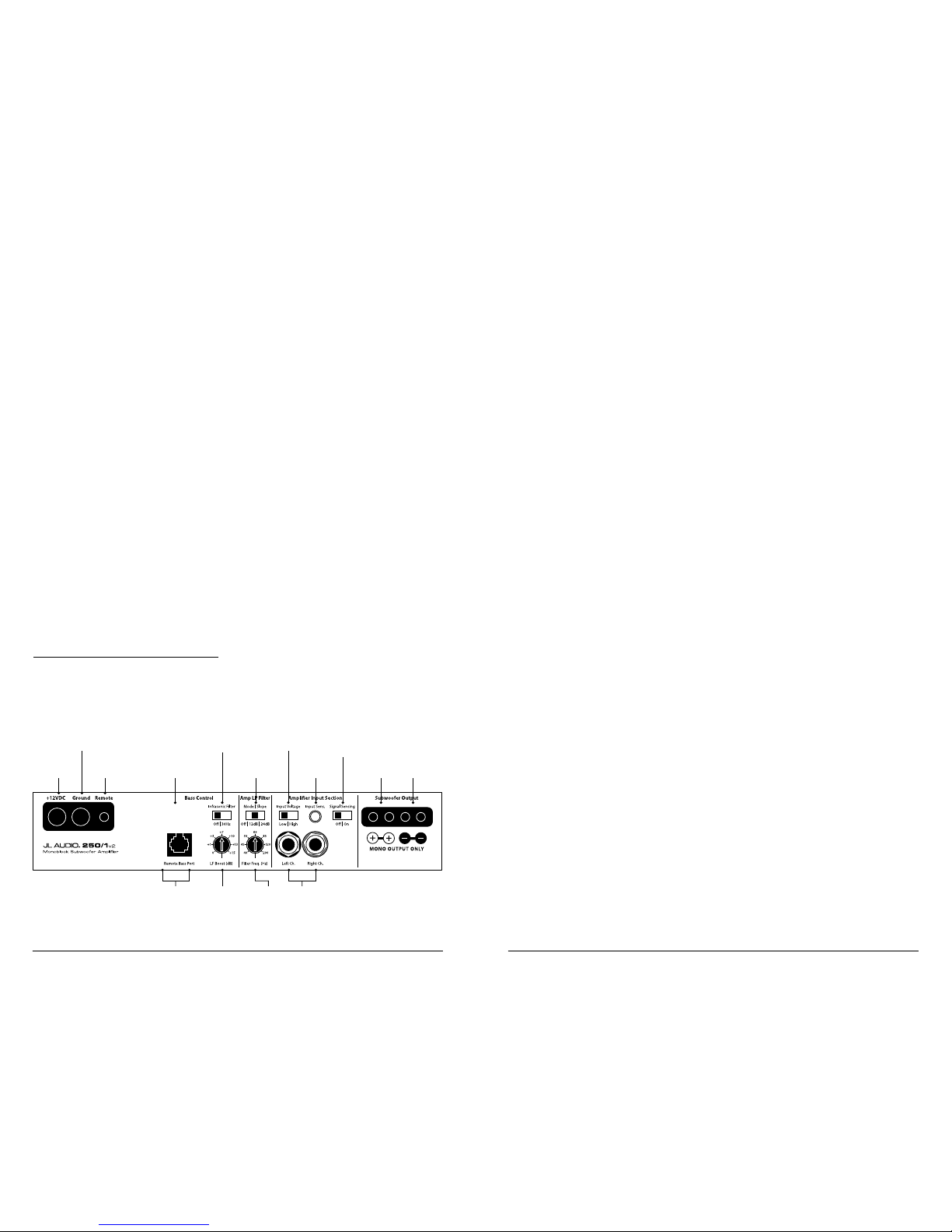
Remote Turn-On
Connector
(pg. 6)
Chassis Ground
Connector
(pg. 5)
+12 V Power
Connector
(pg. 5)
Positive
Subwoofer
Outputs
(pg. 10)
Negative
Subwoofer
Outputs
(pg. 10)
Selects
Boost Level
for Bass EQ
(pg. 9)
Left and Right
Preamp Output Jacks
(pg. 8)
Left and Right
Input Jacks
(pg. 7)
Selects Low-Pass
Filter Frequency for
Amplifier Channel
(pg. 8)
Input Sensitivity
Control
(pg. 7)
Input Voltage
Range Selector
(pg. 7)
Infrasonic Filter
On/Off Switch
(pg. 9)
Signal Sensing
Turn-On
On/Off Switch
(pg. 6)
Amplifier
Low-Pass Filter
Slope
Selection/Defeat
Preamp Output
Mode Selector
(pg. 8)
4 | JL Audio - 250/1v2 Owner’s Manual
5
POWER CONNECTIONS
Before installing the amplifier,
disconnect the negative (ground) wire
from the vehicle’s battery. This will prevent
accidental damage to t he system, the vehicle
and your person during installation.
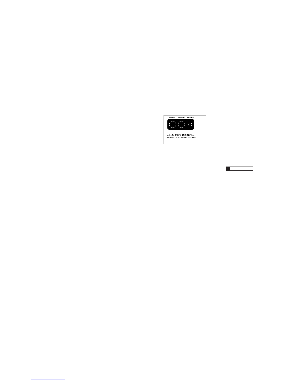
The 250/1v2’s “+12 V DC” and “Ground ”
connections are designed to accept 8 AWG 4 AWG power wire. 8 AWG is a mini mum power
wire size for this amplifier.
If you are inst alli ng the 250/1v2 with ot her
amplif iers and wish to use a sing le main power
wire, use 4 AWG, 2 AWG or 1/0 AWG main
power wire (depending on the overa ll current
demands of all the ampl ifiers in the system). This
4 AWG, 2 AWG or 1/0 AWG power wi re should
terminate into a distr ibution block mounted as
close to the amplifiers a s possible and should
connect to t he 250/1v2 with 8 AWG or 4 AWG
power wire.
Note: that sma ller AWG numbers mean bigger
wire and v ice-versa (1/0 AWG is the la rgest,
2 AWG is smaller, then 4 AWG, then
8 AWG, etc.).
To connect the power wi res to the amplifier,
first back out the set screw on the top of the
termina l block, using the supplied 2.5 mm hex
wrench. Strip 1/2 inch (12 mm) of insulat ion from
the end of each w ire and insert the bare wire into
the terminal block, seating it firmly so that no
bare wire is exposed. While holding the wire in
place, tig hten the set screw firm ly, taking c are not
to strip the head of the screw.
The ground connection shou ld be made using
the same gauge wire as the power connection
and should be kept as short as possible, while
accessing a solid piece of sheet metal in the
vehicle. The su rface of the sheet metal should
be sanded at t he contact point to create a clean,
metal-to-metal connection between the chassis
and the termination of the ground wire. For
optimal grounding , we recommend the u se of a
JL Audio ECS master ground lug (XB-MGLU).
Alternatively, a sheet metal sc rew or bolt can be
used with a star washer.
Any wires r un through metal barriers (such as
firewa lls), must be protected with a high quality
insulat ing grommet to prevent damage to the
insulat ion of the wire. Failure to do so may result
in a dangerous short circ uit.
IMPORTANT
!
Many vehicles employ small (10 AWG 6 AWG) wire to ground the battery to the
vehicle chas sis and to connect the alternator’s
positive connection to the battery. To prevent
voltage drops, t hese wires should be upg raded
to 4 AWG when installing amplifier systems
with main fuse ratings above 60A.
FUSE REQUIR EMENTS
It is absolutely vital that the main power
lead to the amplifier(s) in the system be fused
withi n 18 i nches (45 cm) of the posit ive battery
post connec tion. The fuse va lue at each power
wire should be high enough for all of t he
equipment being r un from that power wire.
If only the 250/1v2 is being run f rom that power
wire, we recommend a 30A fuse be used. AGU
(big glass fuse), MaxiFuse™ (big plastic-body fuse)
or AFS (mini-blade fuse) ty pes are recommended.
No fuse is required or recommended d irectly
before the ampl ifier power con nection. If one is
desired, we recommend the use of a 30A AGU,
AFS or MaxiFuse™ type fuse.
PRODUCT DESCRIPTION
The JL Audio 250/1v2 is a monoblock
subwoofer ampli fier utilizing proprietar y and
patented Class D technology. Its frequency
response is limited to the range below 500
Hz. It is not desig ned for driving midra nge
speakers or tweeters. Every aspect of its
operation has been optimized for low-frequency
amplification. For detailed specifications,
please refer to Append ix C (page 13).
TYPICAL INSTALLATION SEQUENCE
The followi ng represents the s equence
for a typical amplifier installation, using an
after market source unit or OEM Interface
processor (like the CleanSweep CL441dsp).
Additiona l steps and different procedures may
be required in some applications. If you have
any questions, please contact your authorized
JL Audio dealer for assistance.
1) Disconnect the negative batter y post
connection and secure the disconnected cable
to prevent accidenta l re-connection duri ng
installation. This step is not optional.
2) Run power wi re (minimum 8 AWG) from the
battery location to the amplifier mounting
location, taking care to route it in such a
way that it wi ll not be damaged and will not
interfere with vehicle operation. Use 4 AWG
or larger power w ire and a power di stribution
block if additional amplifiers are being
installed with the 250/1v2.
3) Connec t power wire to the positive battery
post. Fuse t he wire with an appropriate fuse
block (and connectors) within 18 inches (45
cm) wire lengt h of the positive batter y post.
This fuse is essent ial to protect the vehicle. Do
not install the fu se until t he power wire has
been securely connected to the amplifier.
4) Run signal cables and remote turn-on wire
from the source unit to the f inal amplifier
mounting location.
5) Run speaker cables from t he speaker systems
to the ampli fier mounti ng location.
6) Find a good, sol id metal grounding point
close to the amplifier a nd connect the
negative power wire to it using appropriate
hardware (use of the JL Audio ECS master
ground lug, XB-MGLU is recommended).
Use the same si ze power wire as the wi re
connected to the “+12VDC” connection
(minimum 8 AWG), no longer than 36 inches
(90 cm) from the amplifier to the g round
connection point. In some vehicles, it may be
necessary to upgrade the batter y ground wire.
(See page 5 for important notice).
7) Securely mount the amplif ier using
appropriate hardwa re.
8) Connect the positive a nd negative power
wires to the amplifier. A fuse near the
amplif ier is not necessa ry.
9) Connect the remote tur n-on wire
to the amplifier.
10) Connect the input cables to t he amplifier.
11) Con nect the speaker cables to the ampli fier.
12) Carefu lly review the amplif ier’s control
settings to make sure that they are set
according to the needs of the system.
13) Instal l the power wire fuse (30A for a
single 250/1v2) and reconnect the negative
battery post terminal.
14) Turn on the source unit at a low level
to double-check that the amplifier is
configured correctly. Resist the temptation
to crank it up u ntil you have verified t he
control settings.
15) Make necessary adjustments to the input
sensitivity controls to obtain the right
overall out put and the desired bala nce
in the system. See Appendix A (page 12)
for the recommended input sensitivity
setting method.
16) Enjoy the f ruits of your labor with your
favorite music.
6 | JL Audio - 250/1v2 Owner’s Manual
7
IMPORTANT
!
You cannot use the tu rn-on output to turn on
processors that are in the signal path before the
250/1v2. (Signal will not pass through most
processors when they are not powered up,
meaning that the amplifier will not turn on
until that processor is active).
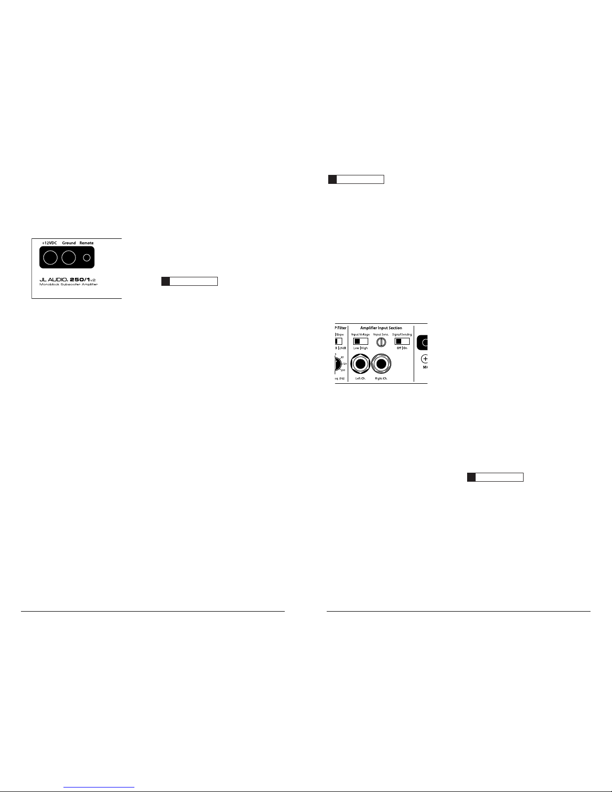
AMPLIFIER INPUT SECTION
The 250/1v2 employs a dif ferential-balanc ed
input topology that provides the user with a high
degree of input f lexibility while retaining superior
noise rejection. This type of circuit also allows
the 250/1v2 to accept high-voltage inputs from
factory source unit outputs without excessive
distort ion or noise problems.
1) Input Connections: A standard left /right
pair of RCA type jacks is used for input on t he
250/1v2. You may run a stereo or a mono signal
into the inputs of t he amplifier. The ampli fier’s
input section automatical ly sums stereo signals
to mono for the internal amplif ier section.
The amplifier wil l operate with only one input
connection (left or rig ht), but will requ ire an
increase in input sensitivity to overcome the loss
of signal. If a mono input signal is to be run, we
recommend that you use a “Y-adaptor” like the
JL Audio ECS model XB-CL RAICY-1F2M to split
the mono signal into both inputs of the amplifier.
2) Input Voltage Range: A wide range of
signal input voltages can be accommodated
by the 250/1v2’s input section (20 0mV – 8V).
This wide range is split up into two sub-
ranges, accessible via switches loc ated in the
“Amplifier Input Section” of t he amplifier.
The “Low” position on the “Input Voltage”
switch selects an input sensitivit y range
between 200mV and 2V. This mea ns that
the “Input Sens.” rotary control wi ll operate
withi n that voltage w indow. If you are using
an aftermarket source unit, with conventional
preamp-level outputs, this is most likely the
position that you will use. The “High” position
on the “Input Voltage” switch selects an input
sensitiv ity range between 80 0mV and 8V. This
is usefu l for certain high-output preamp level
signals as well as speaker-level output from
source unit s and small amplif iers. To use
speaker-level sources, splice the speaker output
wires of the source unit or small amplifier
onto a pair of RCA cables or plugs or use the
JL Audio ECS Speaker Wire to RCA adaptor
(XB-CLRA IC2-SW).
IMPORTANT
!
The output of the amplifier will decrease for a
given input voltage when the “Input Range”
switch is placed in the “High” position.
Conversely, the output will be higher with the
switch in the “Low” position. While this may
sound counter-intuitive, it is consistent with
the descriptions above.
TURNON OPTIONS
The 250/1v2 can be turned on and of f using
two dif ferent methods:
1) A conventional +12V remote turn-on lead.
2) A signal sensing tu rn-on circuit.
To select between the two modes there is a
switch, marked “Signal Sensing”, loc ated i n the
“Amplifier Input Section” of t he front panel.
1) Conventional Remote Turn-On Met hod:
uses a conventional +12V remote turn-on
lead, ty pically controlled by t he source unit’s
remote turn-on output. The amplifier wi ll
turn on when +12V is present at its “Remote”
input and turn off when +12V is switched
off. If a source unit does not have a dedicated
remote turn-on output, the ampl ifier’s turnon lead can be connected to +12V via a switch
that derives power from an ignition-switched
circuit. To use this method, select “Off” on
the “Signal Sensing” switch in the “Amplifier
Input Section”. The 250/1v2’s “Remote”
turn-on connector is designed to accept 12
AWG – 8 AWG wire. 12 AWG is more than
adequate for this purpose. To connect the
remote turn-on w ire to the amplifier, first back
out the set screw on the top of the amplifier,
using the supplied hex wrench. Strip 1/2
inch (12mm) of wire and insert the bare wire
into the receptacle on the front pa nel of the
amplif ier, seating it fi rmly so that no bare wire
is exposed. Smaller w ire than 12 AWG can be
used, but it may be necessar y to strip 1 inch
of insulat ion from the wire and fold the bare
wire in half prior to insertion. While holding
the wire i n the terminal, t ighten the set screw
firm ly, taking c are not to strip t he head of the
screw and ma king sure that the w ire is firmly
gripped by t he set screw.
2) Signal Sensing Turn-On Method: A valuable
feature of the 250/1v2 is its abilit y to be turned
on and off by the presence or lack of signal at
its audio inputs. This al lows you to operate the
amplif ier without having to locate a remote
turn-on lead at the source u nit. This can be
very usef ul if interfacing t he amplifier with
some OEM source u nits that do not have
conventional turn-on leads.
IMPORTANT
!
The sensitiv ity of the signal sensing turn- on
circuit has been designed for h igh-level
(speaker level) signa ls, not for low-level
(preamp level) signals. Using t his feature with
low-level (preamp level) signals is not
recommended. We do not recommend this
method of turning the amplifier on and off as a
default. Whenever possible, use the
conventional remote turn-on lead method. T he
signal sensing circuit is designed to detect
midrange frequency sig nal presence. If the
signal feeding the ampl ifier is not full-ra nge
(for example, if there is an active low-pass
crossover in line before the ampl ifier), this
circuit will not operate properly.
To activate the sig nal sensing turn-on feature,
place the “Sig nal Sensing” switch in t he “On”
position. This should only be done if there is
no conventional turn-on lead connected to the
amplifier’s “Remote” connector. When in the
“On” position, the sig nal sensing circu it will
monitor the audio i nput signal a nd turn the
amplifier on when signal is present. After about
25 seconds of no signal, the amplifier w ill shut off.
Turning on other amplifiers in signal sensing
mode: When t he signal sensing circuit is turned
on, the “Remote” Connector on the ampl ifier
may be used as a remote t urn-on source for other
amplifiers in the system. +12V will be present
at the connector when the amplifier tu rns on in
signal sensing mode and w ill not be present when
the ampli fier tur ns off.
 Loading...