

JL Audio Slash v2 1000/1V2, 1000/1v2 Owner's Manual
Thank you for purchasing a JL Audio amplifier for
your automotive sound system.
Your amplifier has been designed and manufactured to exacting
standards in order to ensure years of musical enjoyment in your vehicle.
For maximum performance and extended warranty
coverage, we highly recommend that you have your new amplifier
installed by an authorized JL Audio dealer. Your authorized
dealer has the training, expertise and installation equipment to ensure
optimum performance from this product. Should you
decide to install the amplifier yourself, please take the time
to read this manual thoroughly so as to familiarize yourself
with its installation requirements and setup procedures.
If you have any questions regarding the instructions in this
manual or any aspect of your amplifier’s operation, please contact your
authorized JL Audio dealer for assistance. If you need further assistance,
please call the JL Audio Technical Support Department
at (954) 443-1100 during business hours.
OWNER’S MANUAL
monoblock subwoofer amplifier
2 | JL Audio - 1000/1v2 Owner’s Manual
3
Selects Output Filter
Cuto Frequency
(pg. 8)
Selects Infrasonic
Filter Cuto
Frequency
(pg. 9)
Selects Low-Pass
Filter Frequency for
Amplier Channel
(pg. 8)
Left and Right
Preamp Output Jacks
(pg. 8)
Left and Right
Input Jacks
(pg. 6)
Bass EQ
Defeat Switch
(pg. 9)
Jack for
Remote Bass
Control Knob
(pg. 9)
Infrasonic Filter
Defeat Switch
(pg. 9)
Preamp Output
Filter Slope
Selector
(pg. 8)
Input Sensitivity
Control
(pg. 7)
Parametric EQ
"Q" (Bandwidth
Selection Control
(pg. 9)
Positive
Subwoofer
Outputs
(pg. 10)
Input Voltage
Range Selector
(pg. 6)
Preamp Output
Mode Selector
(pg. 8)
Amplier Low-Pass
Filter Slope
Selection / Defeat
(pg. 7)
Reverses Polarity
of Amp Output
(pg. 10)
Selects Low-Pass
or High-Pass Mode
for Output Filter
(pg. 8)
Parametric EQ
Center Frequency
Selection Control
(pg. 9)
Parametric EQ
Boost Control
(pg. 9)
Negative
Subwoofer
Outputs
(pg. 10)
Remote Turn-On
Connector
(pg. 6)
Chassis Ground
Connector
(pg. 5)
+12 V Power
Connector
(pg. 5)
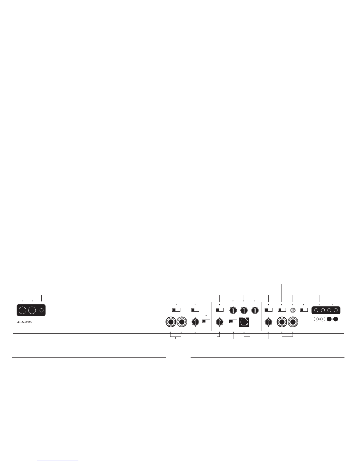
+12VDC Ground Remote Preamp Output Section Infrasonic Filter “Q” Center Freq. Boost (dB) Amp LP Filter
Advanced
Bass
Control
Amplifier Input S ection Subwoofer Output
MONO OUTPUT ONLY
Left Output Right Output Left Ch. Right Ch.Filter Freq. (Hz) Filter Freq. (Hz)Infrasonic Freq. (Hz) Remote Bass Port
Full Range | Amp Filter | Out Filter
Output Mode Filter Slope Mode Mode | Slope Input Voltage Input Sens.
Output Polar ity
12dB | 24dB
Filter Mode
LP | HP
Bass EQ
Off | On
Off | 12dB | 24dB Low | High
Normal|Reversed
Off | On
40
45
556585
120
200 15
18
253040
50
60 40
45
556580
100
200
0.5
0.7
1.1
1.6
2.7
4.3
20
25
354555
70
80 0
+4
+10
+13
+15
1000/1v2
Monoblock Subwoofer Amplifier
Cooling Efficiency Consid erations:
Your JL Audio amplifier employs an
advanced type of heat management, cal led
RealSink™. This feature takes advantage of
convection and radiation effects to remove
heat from the amplifie r circuitry. For opt imum
cooling performance, the vertical heat sinks
located at the back of the amplifier shou ld be
exposed to as large a volume of air as possible.
Enclosing the amplifier in a small, poorly
ventilated chamber can lead to excessive heat
build-up a nd degraded per formance. If a n
insta llation cal ls for an enclosure around the
amplif ier, we recommend that this enclosure
be ventil ated with the aid of a fan. I n normal
applications, fan-cooling is not necessary, but
you sti ll need to follow s ome basic guidel ines:
• Amplifier mounted vertically with heat sink fins
pointing up: Optimum
• Amplifier mounted horizontally,
right side up: Good
• Amplifier mounted horizontally, but upside
down: Fair (not recommended if there is
less than 1 inch (2.5 cm) clearance above the
amplif ier heat sinks)
• Amplifier mounted vertically with heat sink fins
pointing lateral ly: Fair
• Amplifier mounted vertically with heat sink fins
pointing down: Poor (not recommende d)
If mounting the amplifier under a seat,
make su re there is at lea st 1 inch (2.5 c m) of
space above the amplif ier’s outer shel l to permit
proper coolin g.
Safety Considerations:
Your amplifier needs to be installed in a dry,
well-ventila ted environment a nd in a manner
which does not interfere with your vehicle’s safety
equipment (air bags, seat belt systems, ABS brake
systems, etc.). You should also take the time to
securely mount the ampli fier using appropr iate
hardware so that it does not come loose in t he
event of a co llision or a sudden jolt to the vehicle.
Stupid Mistakes to Avoid:
• Check before drilling any holes in your vehicle
to make sure that you will not be drilling
throug h a gas tank , brake line, wiring har ness or
other v ital vehicle sys tem.
• Do not run system wiring outside or underneath
the vehic le. This is a n extremely da ngerous
practice which can result in severe damage to
your vehic le and person.
• Protect all system wires from sharp metal
edges and wear by carefully routing them,
tying them down and using grommets and
loom where appropriate .
• Do not mount the amplifier in the engine
compart ment, under the ve hicle, on the roof
or in a ny other area th at will exp ose the
amplifier circuitry to the elements.
PROTECT YOUR H EARING!
We value you as a long-term customer. For
that rea son, we urge you to pr actice restra int in
the oper ation of this produc t so as not to d amage
your hearing and that of others in your vehicle.
Studies have shown that cont inuous exposure to
high sound pressure levels can lead to permanent
(irrepara ble) hearing loss . This and a ll other
high-power a mplifiers ar e capable of producing
such hig h sound pressure le vels when connect ed
to a spea ker system. Plea se limit your continuous
exposu re to high volume le vels.
While driving, operate your audio system in
a manner that stil l allows you to he ar necessar y
noises to operate your vehicle safely (horns,
sirens, etc.).
SERIAL NUMBER
In the event that your a mplifier requi res
serv ice or is ever stolen, you will nee d to
have a record of the product’s serial number.
Please take the time to enter that number in
the space provided below. The serial number
can be found on the bot tom panel of the
amplif ier and on the amplifier pac kaging.
Serial Number:
INSTALLATION APPLICATIONS
This amplifier is designed for operation in
vehicles with 12V, negative-ground electrical
systems. Use of this product in vehicles with
positive ground and/or voltages other than 12V
may result in damage to the product and will void
th e w arr ant y.
This product is not certified or approved for
use in aircraft.
Do not att empt to “bridge” t he outputs of th is
amplif ier with the outputs of a second amplifier,
includin g an identical one.
PLANNING YOUR INSTALLATION
It is important that you take the time to read
this m anual and t hat you plan out your
insta llation caref ully. The followi ng are some
considerat ions that you must t ake into account
when plan ning your ins tallation.
4 | JL Audio - 1000/1v2 Owner’s Manual
5
POWER CONNECTIONS
Before installing the amplifier,
disconnect the negative (ground) wire
from the vehicle’s battery. This will prevent
accidental damage to the system, the vehicle
and your person during i nstallation.
+12VDC Ground Remote Preamp Output Section Infrasonic Filter “Q” Center Freq. Boost (dB) Amp LP Filter
Advanced
Bass
Control
Amplifier Input Sec tion Subwoofer Output
MONO OUTPUT ONLY
Left Output Right Output Left Ch. Right Ch.Filter Freq. (Hz) Filter Freq. (Hz)Infrasonic Freq. (Hz) Remote Bass Port
Full Range | Amp Filter | Out Filter
Output Mode Filter Slope Mode Mode | Slope Input Voltage Input Sens.
Output Polarit y
12dB | 24dB
Filter Mode
LP | HP
Bass EQ
Off | On
Off | 12dB | 24dB Low | High
Normal|Reversed
Off | On
40
45
556585
120
200 15
18
253040
50
60 40
45
556580
100
200
0.5
0.7
1.1
1.6
2.7
4.3 20
25
354555
70
80 0
+4
+10
+13
+15
1000 /1v2
Monoblock Subwoofer Amplifier
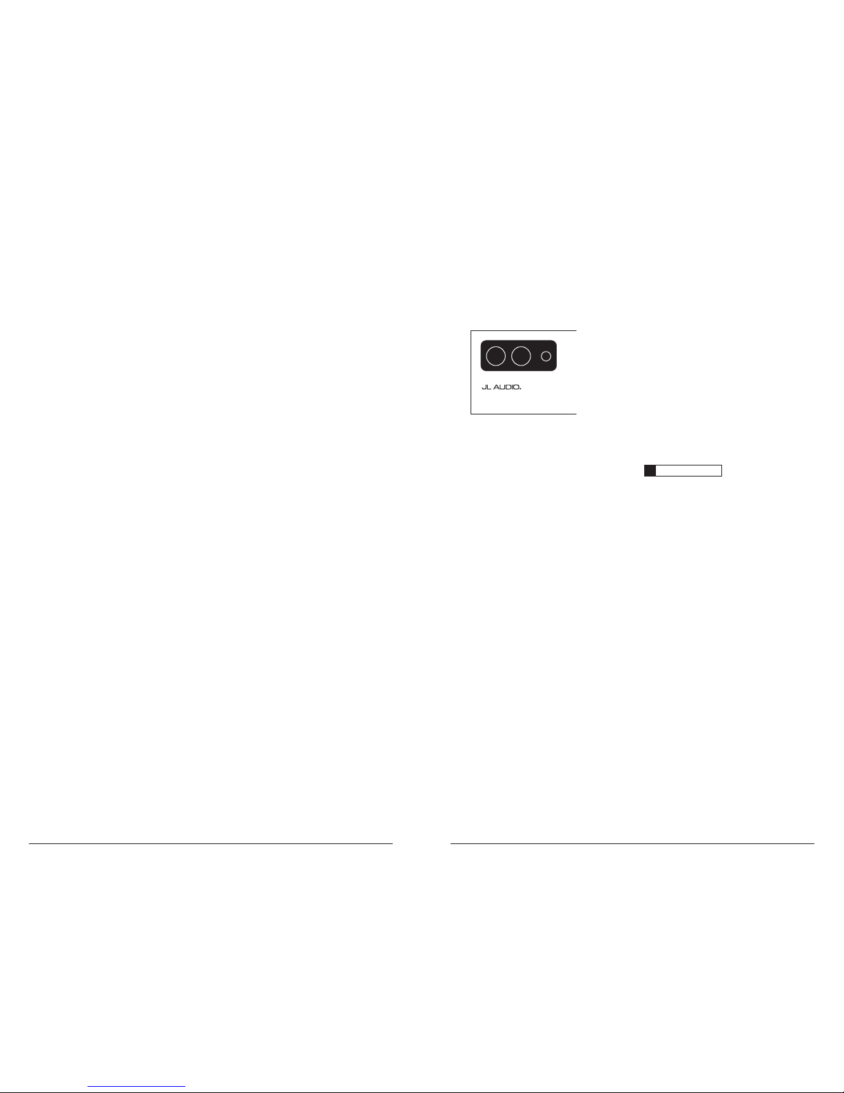
The 100 0/1's “+1 2 V D C” and “Ground”
connect ions are designed to accept 4 AWG power
wire. 4 AWG is the only recommended power
wire size for this amplifier.
If you are installi ng the 1000/1 wit h other
amplif iers and wish to use a single main power
wire, use 2 AWG or 1/0 AWG main power wire
(depending on the overall current demands of all
the amplifiers in the system). This 2 AWG or
1/0 AWG power wire shoul d terminate into
a distribution block mounted as close to the
amplifiers as possible and should connect to the
1000/1 with 4 AWG power wire.
Note: that smaller AWG numbers mean bigger
wire a nd vice-versa (1/0 AWG is biggest, 2 AWG
is smaller, then 4 AWG, then 8 AWG, etc.).
To connect the power wires to the amplifier,
first back out the set screw on the top of the
amplifier, using the supplied 2.5 mm hex wrench.
Strip 1/2 inch (12 mm) of insulation from the
end of each wire and insert the bare wire into the
receptacle on the front panel of the amplifier,
seating it firmly so that no bare wire is exposed.
While holding the wire in place, tighten the set
screw firmly, taking care not to strip the head
of the sc rew.
The grou nd connection shou ld be made
using 4 AWG wire and should be kept as short
as possible, while accessing a solid piece of sheet
metal i n the vehicle. T he surface of t he sheet
metal s hould be sanded at the contact poi nt to
create a cle an, metal-to-meta l connection be tween
the chassis and the termination of the ground
wire. For optimal grounding, we recommend
the use of a JL Audio ECS master ground
lug (XB -MGLU). Altern atively, a sheet metal
screw or bolt can be used with a star washer.
Any wires run through metal barriers (such as
firewa lls), must be protec ted with a hi gh quality
insulat ing grommet to prevent damage to t he
insulation of the wire. Failure to do so may result
in a dangerous short circuit.
IMPORTANT
!
Many vehicles employ small (10 AWG -
6 AWG) wire to ground the battery to the vehicle
chassis a nd to connect t he alternator’s positive
connection to the battery. To prevent voltage
drops, these wires should be upgraded to 4
AWG (or larger) when installin g a 1000/1v2.
FUSE REQUIREMENTS
It is absolutely vital that the main power
lead to the amplifier(s) in the system be fused
within 18 inches (45 cm) of the positive battery
post connection. The fuse value at each power
wire should be high enough for all of the
equipment being run from that power wire.
If only t he 1000/1v2 is being run from that power
wire, we recommend a 100A AN L fuse be use d.
No fuse is required directly before the
amplif ier power connect ion. If one is desi red,
we recommend the use of a 100A A NL fuse for
each 1000/1v2.
PRODUCT DESCRIPTION
The JL Audio 1000/1v2 is a monoblock
subwoofer amplifier utilizing proprietary and
patented Class D technology. Its frequency
response i s limited to t he range below 250 Hz. It
is not designed for driving midrange speakers or
tweeters. Every aspect of its operation has been
optimized for low-frequency amplification.
For detai led specific ations, please re fer to
Appendix B (page 15).
TYPICAL INSTALLATION SEQUENCE
The following represents the sequence
for a ty pical amplif ier instal lation, using a n
after market source u nit or OEM Interfa ce
processor (like the CleanSweep® CL441dsp).
Additional steps and different procedures may
be required in some applications. If you have
any questions, please contact your authorized
JL Audio dea ler for assista nce.
1) Disconnect the negative battery post
connection and secure the disconnected cable
to prevent accidental re-connection during
insta llation. This step is not optional!
2) Run power wire (minimum 4 AWG)
from the battery location to the amplifier
mounting location, taking care to
route it in such a way that it will not be
damage d and will not interfere with
vehicle oper ation. Use 2 AWG or 1/0
AWG power w ire if additiona l amplifiers
are being installed with the 1000/1v2.
3) C onnect power wi re to the positive battery
post. Fuse the wire with an appropriate fuse
block (and con nectors) within 18 inches
(45 cm) wire len gth of the p ositive battery
post. This fuse is essential to protect the
vehicle. Do not install the fuse until the power
wire has been connected to the amplifier.
4) Run signal cables (RCA cables) and remote
turn-on wire from the source unit to the
amplifier mounting location.
5) Run speaker wire from the speaker systems to
the ampl ifier mounti ng location.
6) Find a good, solid metal grounding point
close to t he amplifier and connect t he
negative power wire to it usi ng appropriate
hardware. Use minimum 4 AWG power wire,
no longer than 36 inches (90 cm) from the
amplifier to the ground connection point. In
some vehicles, it may be necessary to upgrade
the bat tery ground w ire. (See page 5 for
importa nt notice).
7) Securely mount the amplifier using
appropriate hardware.
8) Connect the positive and negative power
wires to the amplifier. A fuse near the
amplif ier is not necess ary.
9) C onnect the remote turn-on wire
to the a mplifier.
10) Connect the RCA input cables
to the a mplifier.
11) C onnect the spe aker wires to the amplif ier.
12) Carefully review the amplifier’s control
settings to make sure that they are set
according to the needs of the system.
13) Instal l power wire fuse (100A for a
single 100 0/1v2) and recon nect the negati ve
battery post terminal.
14) Turn on the source un it at a low level
to double-check that the amplifier is
config ured correct ly. Resist t he temptation
to crank it up until you have verified the
control set tings.
15) Ma ke necessar y adjustments to t he input
sensitivity controls to obtain the right
overall output and the de sired balance
in the system. See Appendix A (page 14)
for the recommended input sensitivity
setting method.
16) Enjoy the fruits of your labor with your
favorite music .
6 | JL Audio - 1000/1v2 Owner’s Manual
7
The ampl ifier wil l operate with only one input
connection (left or right), but will require an
increase in input sensitivity to overcome the loss
of signal. If a mono input signal is to be run, we
recommend that you use a “Y-adaptor” like the
JL Audio E CS model XB- CLRAICY-1F2M to split
the mono si gnal into bot h inputs of the a mplifier.
2) Input Voltage Ra nge: A wide range of signal
input voltages can be accommodated by
the 1000/1v2’s input section (200mV – 8V).
This w ide range is spl it up into two sub-
ranges, accessible via switches located in the
“Amplifier Input Section” of the amplifier.
The “Low ” position on t he “Input Voltage”
switch s elects an input sensitivity r ange
between 200mV and 2V. This means that
the “Input Sens.” rotary c ontrol will ope rate
within that voltage window. If you are using
an aftermarket source unit, with conventional
preamp-level outputs, this is most likely the
position t hat you will use. The “High” position
on the “I nput Vo ltage” switch selects an input
sensitivity range between 800mV and 8V. This
is usef ul for certa in high-output pre amp level
signals as well as speaker-level output from
source units and small amplifiers. To use
speaker-level sources, splice the speaker output
wires o f the source un it or small a mplifier
onto a pair of RCA cables or plugs or use the
JL Audio E CS Speaker Wir e to RCA adaptor
(XB-CLRA IC2-SW).
IMPORTANT
!
The output of the amplifier will decrea se
for a given input voltage when the “Input
Range” s witch is placed i n the “High” position.
Conversely, the output will be higher with
the switch in the “Low” position. W hile this
may sound counter-intuitive, it is correct
as described.
3) Input Se nsitivity Adjust ment: Located
next to t he “Input Voltage” switch, in the
“Amplifier Input Section”, is a rotary control
labeled “Input Sens.”. Once the appropriate
“Input Voltage” range has been selected, this
rotar y control can be used to match the source
unit’s output voltage to the input stage of the
amplifier for maximum clean output. Rotating
the contr ol clockwise w ill result in higher
sensitivity (louder for a given input voltage).
Rotating the control counter- clockwise w ill
result in lower sensitivity (quieter for a given
input voltage). To properly set the amplifier
for maximum clean output, please refer to
Appendix A (page 14) in this manual. After
using this procedure, you can then adjust
the level of the amplifier by adjusting the
input sensitivity downward, if the amplifier
requires attenuation to ach ieve the desired
system ba lance. Do not i ncrease the “Input
Sens.” setting for any amplifier in the system
beyond the maximum le vel established du ring
the procedure outlined in Appendix A (page
14). Doing so will result in audible distortion
and poss ible speaker da mage.
REMOTE TURNON
The 1000/1v2 uses a conventional +12V remote
turn-on lead, typically controlled by the source
unit's remote turn-on output. The amplifier will
turn on when +12V is prese nt at its “Remote ”
input and turn off when +12V is switched off. If
a source u nit does not have a dedicated remote
turn-on output, the amplifier’s turn-on lead can
be connec ted to +12V via a switch that derives
power from an ignition-switched circuit.
The 100 0/1's “Remote” t urn-on connector is
designed to accept 12 AWG – 8 AWG wire.
12 AWG is more than adequate for this purpose.
To connect the remote turn-on wire to the
amplif ier, first back out the set screw on the
top of the amplifier, using the supplied hex
wrench. Strip 1/2 inch (12mm) of wire and
insert the bare wire into the receptacle on the
front panel of the amplifier, seating it firmly so
that no bare wire is exposed. Smaller wire than
12 AWG can be use d, but it may be nece ssary
to strip 1 inch of insulation from the wire and
fold the ba re wire in ha lf prior to ins ertion.
While holding the wire in the terminal, tighten
the set screw firm ly, taking ca re not to strip
the head of the screw and making sure that
the wi re is firm ly gripped by t he set screw.
+12VDC Ground Remote Preamp Output Section Infrasonic Filter “Q” Center Freq. Boost (dB) Amp LP Filter
Advanced
Bass
Control
Amplifier Input Sec tion Subwoofer Output
MONO OUTPUT ONLY
Left Output Right Output Left Ch. Right Ch.Filter Freq. (Hz) Filter Freq. (Hz)Infrasonic Freq. (Hz) Remote Bass Port
Full Range | Amp Filter | Out Filter
Output Mode Filter Slope Mode Mode | Slope Input Voltage Input Sens.
Output Polarit y
12dB | 24dB
Filter Mode
LP | HP
Bass EQ
Off | On
Off | 12dB | 24dB Low | High
Normal|Reversed
Off | On
40
45
556585
120
200 15
18
253040
50
60 40
45
556580
100
200
0.5
0.7
1.1
1.6
2.7
4.3 20
25
354555
70
80 0
+4
+10
+13
+15
1000 /1v2
Monoblock Subwoofer Amplifier
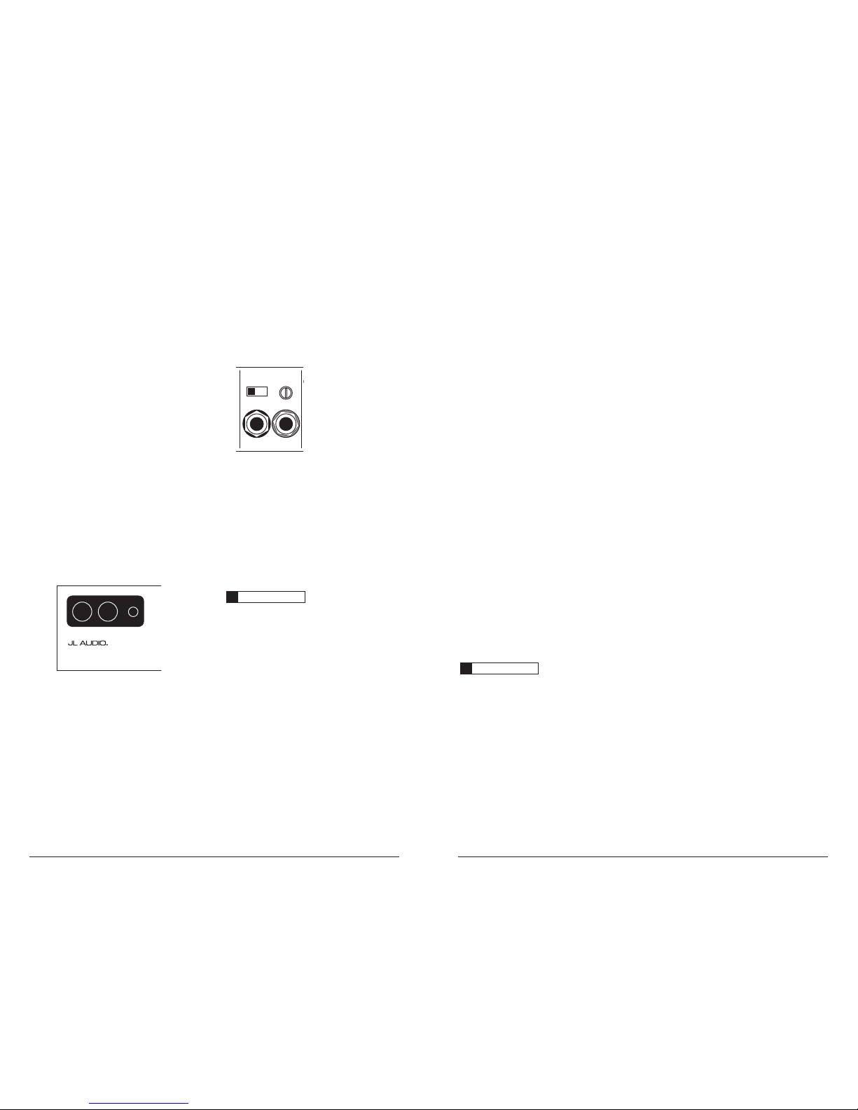
AMPLIFIER INPUT SECTION
The 1000/1v2 employs a differential-balanced
input topolog y that provides the user wit h a high
degree of input flexibi lity while retaining sup erior
noise rejec tion. This t ype of circu it also allows
the 1000/1v2 to accept high-voltage inputs from
factory source unit outputs without excessive
distort ion or noise problems.
Amplifier Input Sec tion Subwoofer Output
MONO OUTPUT ONLY
Output Polarit y
|
High
Normal|Reversed
1) Input Connec tions: A standard left/right pair
of RCA ty pe jacks is u sed for input on
the 1000/1v2. You may run a stereo or a mono
signal into the inputs of the amplifier. The
amplifier’s input section automatically sums
stereo signals to mono for the internal
amplif ier section an d for the “LP” “Filter
Mode” of t he “Preamp Output ” section.
IMPORTANT
!
If you plan to use the “Preamp Output” in
“Full-Range” or “HP” mode to feed a stereo
amplif ier, you must con nect a stereo sig nal to
the input of the amplifier. A mono signal into
the amplifier wil l result in a mono signal out of
the preamp output. (It’s a great amplifier, but it
doesn’t do mag ic).
 Loading...