

Page 1
SB-VW-GTI/10W6v2
2006-Up
GTI MkV, Rabbit & R32
SB-VW-GTI/10W6v2_INSTR_SKU#011250
SB-VW-GTI/10W6v2_INSTR_SKU#011250
2
1 H OUR
INSTALLATION GUIDE
for the
SB-VW-GTI/10W6v2
2006-Up
Thank you for choosing a JL Audio Stealthbox® for your automotive sound system. With proper
installation, your new vehicle-specific enclosed subwoofer system will deliver years of listening pleasure.
We strongly recommend that you have your new Stealthbox® installed by your authorized JL Audio
dealer. The installation professionals employed by your dealer have the necessary tools and experience
to disassemble and reassemble your vehicle properly. If you prefer to perform your own installation,
please read this installation guide completely
GTI MkV, Rabbit & R32
before beginning the process.
If you choose to perform the installation yourself, it is absolutely vital that
the Stealthbox
instructions. Failure to mount the enclosure properly presents two problems:
1) The sub-bass performance will suffer due to the movement of the enclosure
caused by the force exerted by the woofer(s).
2) A loose enclosure presents a serious safety hazard in the event of a collision
or sudden deceleration.
13 1/2-inches
®
be properly mounted to the vehicle according to these
STEP 1
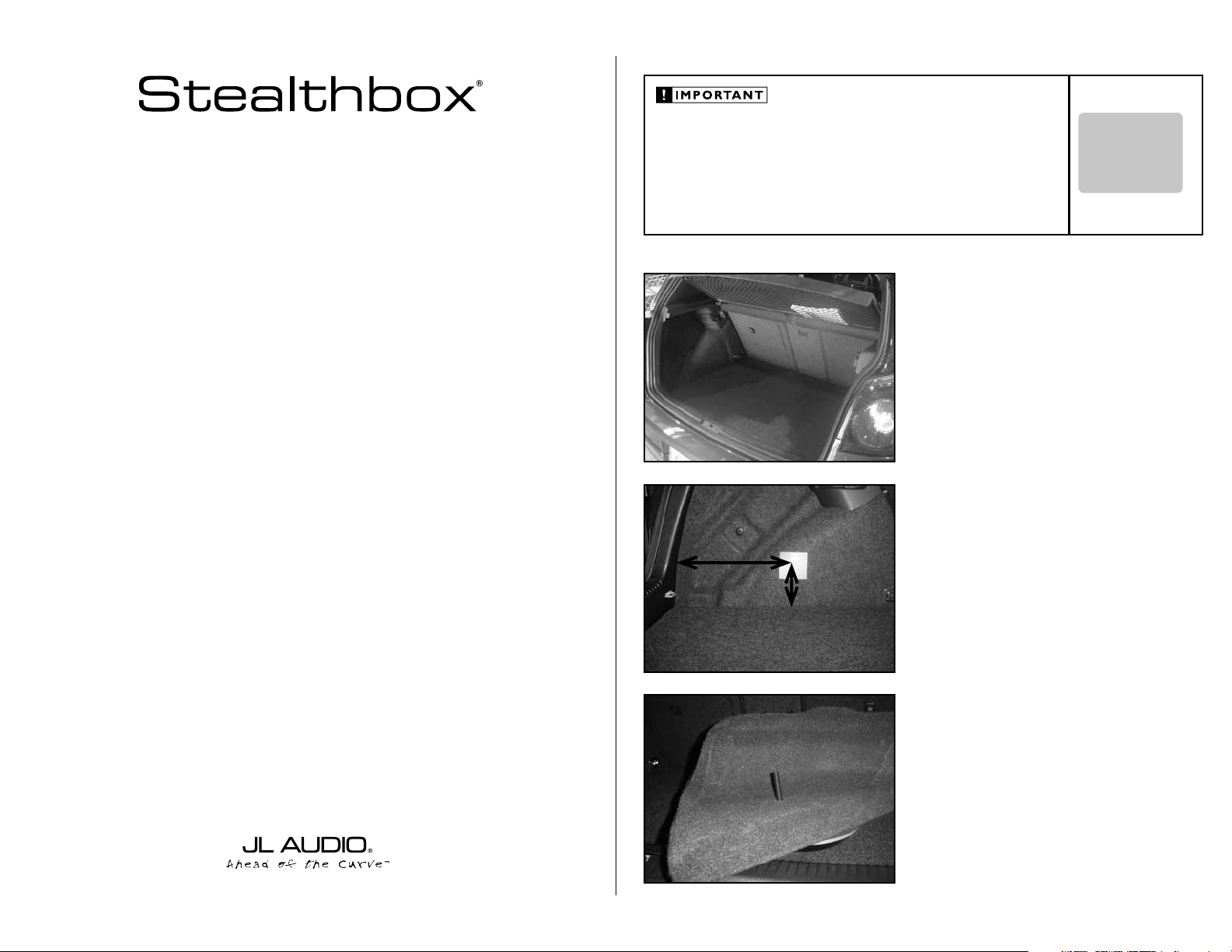
Remove any contents from the cargo area.
STEP 2
Place the supplied wax square onto the driver’s side rear
cargo panel.
6-inches
INSTALLATION
DIFFICULTY:
OUT
OF
5
ESTIMATED TIME:
1 HOUR
STEP 3
Thread the supplied socket cup screw into the rear of the
Stealthbox®.
Continued on Next Page
Page 2
SB-VW-GTI/10W6v2_INSTR_SKU#011250
SB-VW-GTI/10W6v2_INSTR_SKU#011250
*Read the next three steps to fully understand
this procedure.*
STEP 4
Place the Stealthbox® into the mounting location and press
firmly onto the Stealthbox®.
STEP 4A
The Stealthbox® needs to fit all the way to top plastic panel.
STEP 4B
The Stealthbox® will be raised off the floor. This is to allow
the factor y flooring to be pulled from the cargo area, once
the Stealthbox® is installed.
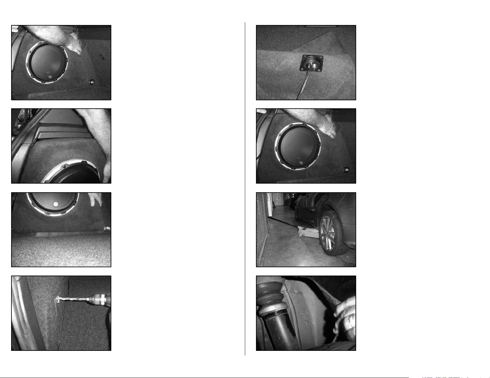
STEP 6
Run sp eaker w i re fro m the am p l ifi er’s locatio n t o the
Stealthbox
®
loca t ion and check for p roper operatio n o f
the woofer.
STEP 7
Place the Stealthbox® into the mounting location. Guide the
socket cup set screw through the drilled hole.
STEP 8
Jack up the driver’s side rear of the vehicle.
You should be able to access the socket cup set screw with
the rear wheel on the car. If necessary, you may remove the
wheel off the car.
Page 2 • JL Audio, Inc 2007
STEP 5
Note: Before drilling, you are drilling into the rear
fender well. Once you protrude to the outside, do not
go any further or you will be paying for a new rear
tire. Always wear eye protection when drilling!
With a drill and a 1/2-inch drill bit, drill through the
impression made in the wax square.
Remove the wax square.
STEP 9
Behind the strut, pull the black plastic guard to gain access to
the protruding socket cup set screw.
Continued on Next Page
Page 3

SB-VW-GTI/10W6v2_INSTR_SKU#011250
STEP 10
lock washer
JLA-SKU#011250 -11-1-200
(1)
3/8-inch -16 x 2 1/2-inch Socket Cup Set Screw
(1)
3/8inch -16 Hex Nut
(1)
3/8-inch Fender Washer
(1)
3/8-inch Flat Washer
(1)
3/8-inch Split Lock Washer
Acoustic Suspension (sealed)
10W6v2-D4
2 ohms mono
400 Watts
P O W E R R E C O M M E N D A T I O N
6.5-inch / Front Doors
TR650-CSi, TR650-CXi, VR650-CSi, VR650-CXi, C5650, C5-650x & ZR650-CS
6.5-inch / Rear Doors / Side Panels
TR650-CXi, VR650-CXi, XR650-CXi & C5-650x
Place a supplied fender washer, flat washer, split
lock washer
and hex nut onto the socket cup set screw. Secure, but do
not over tighten. We know you are “Strong like bull”, but you
do not have to use all your He-man power on this little nut.
Note: For added protection it is recommended that
you apply a bead of silicone between the vehicle and
the fender washer. After the bolt assembly is tightly
secured, it is also recommended that vehicle undercoating material is applied to the exposed assembly
SB-VW-GTI/10W6v2_INSTR_SKU#011250
INCLUDED HARDWARE
(1)
3/8-inch -16 x 2 1/2-inch Socket Cup Set Screw
(1)
3/8-inch Fender Washer
(1)
3/8-inch Flat Washer
(1)
3/8-inch Split Lock Washer
(1)
3/8inch -16 Hex Nut
SPECIFICATIONS
Enclosure Type:
Driver Type:
Nominal Impedance:
Continuous Power Handling:
POWER RECOMMENDATION
Acoustic Suspension (sealed)
10W6 v2-D 4
2 ohms mono
400 Watts
JL Audio recommends using a high quality amplifier such as the JL Audio A1400.
The diagram below shows the recommended crossover, infrasonic filter and equalizer settings for the A1400 when
being used to power your Stealthbox®.
Page 3 • JL Audio, Inc 2007
CONGRATULATIONS
You have completed the installation for this model!
Please refer to the Power Recommendation section for an
amplifier recommendation and basic set-up help.
Input Voltage
Low | High
CH 1 (Left)
CH 2 (Right)
Pre-Outs
Power Protect
Bass Boost Controls
Remote
Bass Port
Bass Boost
Input Sens. LP Filter
Filter Freq. (Hz )
55
45
40
65
80
100
200
The JL Audio A1400 is a very versatile audio component. Please consult the owner’s manual for even more
detailed information about installing and tuning this amplifier.
MID/HIGH FREQUENCY DRIVER FITMENT
A variety of JL Audio coaxial and component systems will fit in the factory speaker locations of you vehicle.
Front Speaker Size / Location:
Fits JL Audio Models:
Rear Speaker Size / Location:
Fits JL Audio Models:
All specifications are subject to change without notice. “JL Audio®” and the JL Audio logo, “Stealthbox” and the Stealthbox logo are registered
trademarks of JL Audio, Inc. “Ahead of the Curve” and its respective logo is a trademark of JL Audio, Inc.
JLA-SKU#011250 -11-1-20077 • Printed in USA • ©2007 JL Audio, Inc. • U.S. PATENTS: #5,734,734 #5,949,898 #6,118,884 #6,229,902 #6,243,479
#6,294,959 #6,501,844 #6,496,590 #6,441,685 #5,687,247 #6,219,431 #6,625,292 #D472,891 #D480,709 Other U.S. & Foreign patents pending.
For more detailed information please visit us online at www.jlaudio.com.
10369 NORTH COMMERCE PARKWAY • MIRAMAR, FLORIDA • 33025 • USA
6.5-inch / Front Doors
TR650-CSi, TR650-CXi, VR650-CSi, VR650-CXi, C5650, C5-650x & ZR650-CSii
6.5-inch / Rear Doors / Side Panels
TR650-CXi, VR650-CXi, XR650-CXi & C5-650x
(954) 443-1100
www.jlaudio.com
 Loading...