

➔
➔
➔
➔
Stealthbox
®
INSTALLATION GUIDE
SB-T-TUNCNSL2/10W3v2, JL AUDIO, Inc 2005
Sheet SKU#011180 Revision 4/6/2005Page 1
for the
SB-T-TUNCNSL2/10W3v2
(‘03-Up Toyota Tundra Access & Double Cab
with front bucket seats and center console)
This Stealthbox is a product which
requires professional installation skills and
tools.
Please read this installation guide thoroughly before beginning the project. It
will guide you step by step through the
installation.Several of the steps in this
process may require two people to
accomplish.
It is absolutely vital that the enclosure
be properly mounted to the vehicle
according to these instructions. Failure
to mount the enclosure properly presents two problems: 1) The sub-bass
performance will suffer due to the
movement of the enclosure caused by
the force exerted by the woofer(s) and
2) A loose enclosure presents a serious
safety hazard in the event of a collision
or sudden deceleration.
Please enjoy your JL Audio Stealthbox
responsibly.
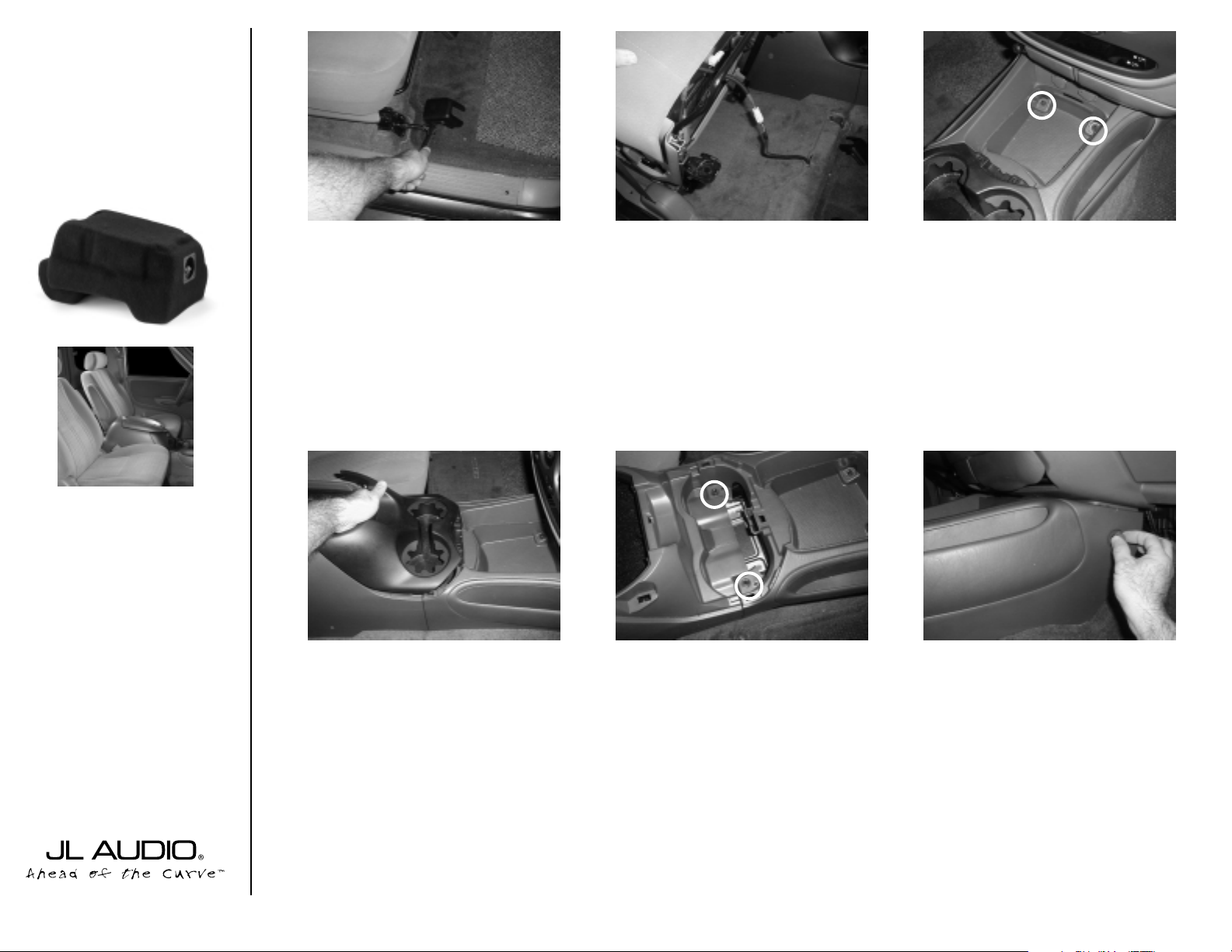
STEP 1:
Using a 14mm socket,remove the
four bolts that secure the passenger side front
seat.
STEP 2:
Tilt the seat to the rear, unplug the
exposed wire assembly, remove the seat from
the truck.
STEP 3:
Remove the front storage access
door. Using a 10mm socket,remove the
exposed bolts.
STEP 4:
With the main storage door open,
grab ahold of the black cup holder section
and pull up.
STEP 5:
Using a 10mm socket,remove the
exposed bolts. Also remove the bolts that are
located at the bottom of the main storage
bucket.
STEP 6:
Remove the plastic buttons that are
located on each side of the center console.
START
HERE
Continued on Next Page ➔
www.jlaudio.com
➔
➔
➔

➔➔
➔➔➔
STEP 7: Slide the center console to the rear of
truck.This will allow exposer of the 12v plug wires.
Unplug and then remove the center console from
truck.
*Tundra Access Cab Only*
Keep the air ducts inside the truck, for now.
STEP 11: Back inside the truck. Remove the black
bracket that is mounted to the floor of the
truck(not pictured).
*Tundra Access Cab Only*
Using a 1/2” drill bit and dr ill. Enlarging the mounting
holes from the bracket.
Cont.
From
Previous
Page
Continued on Next Page ➔
➔
STEP 8: *Tundra Access Cab Only*
With the center console out of the truck, flip up
side down.Remove the two air duct ears that are
located to the rear of the center console.
*Tundra Access Cab Only*
STEP 12: Cut 1-1/2” off of each carpet flap, that is
located in front of the mounting holes, from
STEP10.
➔
*Tundra Access Cab Only*
STEP 13(a): Place only one of the supplied wax
squares into this location.
Place the middle of the supplied wax square, 4-3/4”
back from the front consoles metal mounting bracket.
*Tundra Double Cab Only*
STEP 13(b)
FRONT WAX SQUARE
Place the middle of one of the supplied wax
squares, 4-3/4” back from the front consoles metal
mounting bracket.
REAR WAX SQUARES
Place the middle of the remaining pair of supplied
wax squares, 1-3/4” back from the center console
rear mounting holes.
STEP 9: Remove the 8 screws that is securing
the black plastic support to the outer console . Not
all circles represent all 8 screws.
There are a pair of screws on each side of the console that need to be removed.
STEP 10: *Tundra Access Cab Only*
Now it is time to remove those air ducts from
STEP 7.With the ducts removed, you will need to
cut both ducts. Place the ducts so the front of the
ducts are facing to the right.
Driver’s side: Measure and mark 3/4” from front
of foam tape, back. Cut at location.
Passenger’s side: Cut at the middle of the foam
tape.
SB-T-TUNCNSL2/10W3v2, JL AUDIO, Inc 2005
Sheet SKU#011180 Revision 4/6/2005Pag e 2
www.jlaudio.com
Passenger’s side
middle
Driver’s side
3/4”
4-3/4”
6-1/2”
1-3/4”

➔➔
➔
Cont.
From
Previous
Page
Continued on Next Page ➔
➔
STEP 14: Thread in the three supplied socket cup
set screws into the Stealthbox.Make sure that the
socket ends are on the outside of the Stealthbox.
The rear(left side of pic) threaded rods need to
protrude about 1 1/4” out of the Stealthbox.The
front socket cup set screw needs to protrude about
3/4”.
Place the Stealthbox into location.Slide the rear
socket cup set screw through the drilled out holes
from STEP10. Press fir mly on the front of the
Stealthbox,marking the wax square .
STEP 16(a): *Tundra Access Cab Only*
Remove the Stealthbox.You should have an impression on the wax square.
*CAUTION*
Before drilling, make sure that you are not going to
be drilling into any gas lines, br ake lines, transmission
lines, electrical wir ing, transfer case(4x4 vehicles) or
anything else that might cause a reduction in your
weekly pay.Always wear eye protection when drilling.
With the use of a 1/2” drill bit and dr ill. Drill out the
floor at the impression on the wax square
STEP 16(b): *Tundra Double Cab Only*
Remove the Stealthbox.You should have an impression on the wax square.
*CAUTION*
Before drilling, make sure that you are not going to
be drilling into any gas lines, br ake lines, transmission
lines, electrical wir ing, transfer case(4x4 vehicles) or
anything else that might cause a reduction in your
weekly pay.Always wear eye protection when drilling.
With the use of a 1/2” drill bit and dr ill. Drill out the
floor at the impression on the wax square
SB-T-TUNCNSL2/10W3v2, JL AUDIO, Inc 2005
Sheet SKU#011180 Revision 4/6/2005Pag e 3
www.jlaudio.com
STEP 15: Place the Stealthbox into position,Press
down firmly.

➔
➔➔➔
STEP 23: Apply a supplied flat washer,lock washer and nut onto the three socket sup set screw.
Tightly secure all three nuts..
Cont.
From
Previous
Page
Continued on Next Page ➔
➔
STEP 17: Remove the wax square and run speaker wire.
STEP 21: Place the Stealthbox/center console into
vehicle.Attach the speaker wire to terminal.
Back out the three socket cup screws to 1-1/4:”.
➔
STEP 22: Place Stealthbox/center console upright
and into the proper position. Carefully guiding the
threaded rods through the three drilled holes.
Pop in the four supplied black plastic push rivets,
into the screw holes on each side of the center console.
STEP 20: Place the Stealthbox into the center
console, outside of vehicle .
*Double Cabs Only*
The permanent removal of the rear seat 12v plug is
neded.
STEP 18: *Access Cabs Only*
Replace the modified A/C ducts from STEP 10,
back into the vehicle.
(Stealthbox is only shown in the picture for position
purposes. You do not have to have the Stealthbox in
location to accomplish this step)
STEP 19: With the Stealthbox and the modified
A/C ducts in position. Place the front section of the
center console back into the proper location. Do
not secure at this time.
*Remember to plug in the 12v sockets.*
(Stealthbox is only shown in the picture for position
purposes. You do not have to have the Stealthbox in
location to accomplish this step)
SB-T-TUNCNSL2/10W3v2, JL AUDIO, Inc 2005
Sheet SKU#011180 Revision 4/6/2005Pag e 4
www.jlaudio.com
STEALTHBOX WALL
FENDER WASHER
FLAT WASHER
LOCK WASHER
HEX NUT
THREADED INSERT
VEHICLE SHEET METAL
SOCKET CUP SET SCREW

Specifications:
Enclosure T ype: Sealed
Driver T ype: 10W3v2-D2
Nominal Impedance: 4Ω
Cont. Power Handling: 300Watts
JLAudio recommends using a high quality amplifier such as the JLAudio 250/1. The diagram below shows the recommended
crossover, infrasonic filter and equalizer settings for the 250/1 when being used to power your Stealthbox®.
Included Hardware:
3) Wax Squares
3) 3/8”- 1-1/4” Fender Washer
3) 3/8” Flat Washer
3) 3/8” Split Lock Washer
3) 3/8”-16x2-1/4” Socket Cup Set Screw
3) 3/8”-16 Hex Nut
10369 N. Commerce Pkwy, Miramar, Florida 33025-392 Phone: 954.443.1100 Fax: 954.443.1111
+12VDC Ground Remote
The JLAudio 250/1 is a very versatile audio component. Please consult the owner’s manual for detailed information
about installing and tuning this amplifier.
➔
➔
STEP 24: With the Stealthbox securely mounted
to the vehicle. Secure the plastic console to the
floor, using the factory screws from STEP 5.
STEP 25: Secure the front section of console with
the factory screws, from STEP 3.
Once both por tions of the center console have
been secured. Snap in the cup holder s from
STEP 4, front console storage door from STEP 3
and the plastic buttons from STEP 6.
➔
SB-T-TUNCNSL2/10W3v2, JL AUDIO, Inc 2005
Sheet SKU#011180 Revision 4/6/2005Pag e 5
www.jlaudio.com
Mid/High Frequency Driver Information:
CONGRATULATIONS!
INSTALL COMPLETE.
VR650-CSi
VR650-CXi
Front Location Driver Size:
6.5”
Applicable JL Audio Products:
TR, VR, XR, ZR 650-CSi
mounting plates are needed
Rear Location Driver Size:
6.5”
Applicable JL Audio Products:
TR,VR,XR 650-CXi
mounting plates are needed
Cont.
From
Previous
Page
Difficulty Of Installation:
Preamp Output Section
Output Mode
Full-Range/Low-Pass/High-Pass
JL AUDIO 250/1
monoblock subwoofer amplifier
Left Ch.
Right Ch.
Bass Control
Infrasonic Filter
Off/30Hz
+7
+3
+1
LF Boost (dB)
+10
+13
Amp LP Filter
Mode/Slope
Off/12dB/24dB
Filter Freq. (Hz)
Amplifier Input Section
Input Voltage
Input Sens.
Low/High
Left Ch.
Right Ch.
Signal Sensing
Off/On
 Loading...