

Page 1
➔
➔
➔
➔
➔
Stealthbox
®
INSTALLATION GUIDE
SB-T-SEQ/10W3v2-D2, JL AUDIO, Inc 2002
Sheet SKU#011111 Revision 10/30/02Page 1
for the
SB-T-SEQ/10W3
(Fits 2001 and Up Toyota Sequoia)
This Stealthbox is a product
which requires professional
installation skills and tools.
Please read this installation guide
thoroughly before beginning the
project. It will guide you step by
step through the installation. Several
of the steps in this process may
require two people to accomplish.
It is absolutely vital that the
enclosure be properly mounted to
the vehicle according to these
instructions. Failure to mount the
enclosure properly presents two
problems: 1) The sub-bass
performance will suffer due to the
movement of the enclosure caused
by the force exerted by the
woofer(s) and 2) A loose enclosure
presents a serious safety hazard in
the event of a collision or sudden
deceleration.
Please enjoy your JL Audio
Stealthbox responsibly.
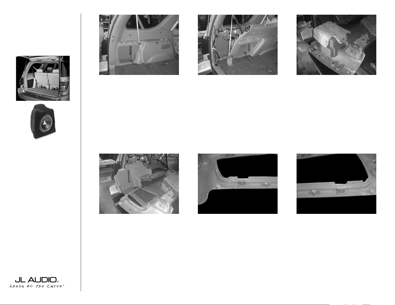
STEP 1:
Remove the driver’s side rear
storage area cover.
STEP 2:
Remove the driver’s side rear panel.
STEP 3:
Grind off the plastic tabs which hold
the pocket to the panel.
STEP 4:
Remove the pocket from the panel.
STEP 5:
Create a notch in the side panel as
shown in the picture.
STEP 6:
Create a second notch in the side
panel as shown in the picture.
START
HERE
Continued on Page 2 ➔
www.jlaudio.com
➔
➔
➔
➔
Page 2
➔➔
➔➔➔
➔
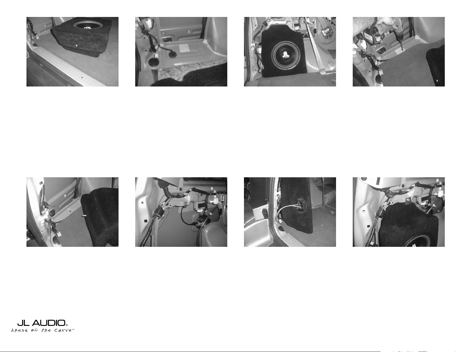
STEP 7:
Insert supplied Socket Set Cup
Screw into the enclosure so the rod extends
approximately 1/4” out of the enclosure.
STEP 11:
Adjust the Socket Cup Set Screw,
so that is extends 1 1/2” out of the enclosure.
Cont.
From
Page 1
Continued on Page 3 ➔
➔
STEP 8:
Roll the floor carpet back to expose
the metal floor in the location shown above.
Place the supplied wax square on the metal
floor as shown above.
STEP 12:
Insert the supplied U-bolt in
factory hole.
(located at the top of the enclosure location
as shown above)
➔
STEP 13:
Run speaker wires to the location
of the Stealthbox. Check the Stealthbox for
proper operation.
STEP14:
Using the supplied 1/4”washer, 1/4”
lock washer and 1/4”x1”bolt. Mount the Lbracker to top of the enclosure.The bottom
of the L-brackt needs to point towards the
driver’s side fender.
STEP 15:
Place the Stealthbox in its proper
location, making sure to place the threaded
rod into the previously drilled hole in the
floor.
STEP16:
Place the supplied 1/4’lock washer,
1/4” flat washer in that order onto the
1/4”x1” bolt. Pass the bolt through the
mounted L-bracker and thread into the Ubolt installed in
STEP 12
. Do not fully tighten.
STEP 9:
Place the Stealthbox into place so as
to allow the Socket Set Cup Screw to make
an impression in the wax square.
STEP 10:
Using a 1/2” drill bit, drill a hole
through the metal floor in the location of the
impression in the wax square.
SB-T-SEQ/10W3v2-D2, JL AUDIO, Inc 2002
Sheet SKU#011111 Revision 10/30/02Page 2
www.jlaudio.com
➔
Page 3
Specifications:
Enclosure Type: Acoustic Suspension (Sealed)
Driver Type: One JL AUDIO 10W3v2-D2 Subwoofer
Nominal Impedance: 4Ω
Cont. Power Handling: 300 Watts
JL Audio recommends using a high quality amplifier such as the JL Audio 250/1. The diagram below shows the recommended
crossover, infrasonic filter and equalizer settings for the 250/1 when being used to power the the Audio Stealthbox®.
Included Hardware:
(2) 1/4" Flat Washer
(2) 1/4" Lock Washer
(1) 1/4” U-Nut
(2) 1/4” x 1” Bolt
(1) L-Bracket
10369 N. Commerce Pkwy, Miramar, Florida 33025-392 Phone: 954.443.1100 Fax: 954.443.1111
+12VDC Ground Remote
The JL Audio 250/1 is a very versatile audio component. Please consult the owner’s manual for detailed information
about installing and tuning this amplifier.
SB-T-SEQ/10W3v2-D2, JL AUDIO, Inc 2002
Sheet SKU#011111 Revision 10/30/02Page 3
www.jlaudio.com
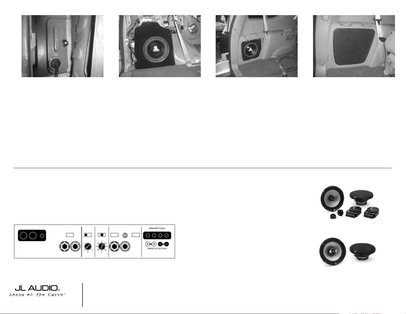
Mid/High Frequency Driver Information:
CONGRATULATIONS!
INSTALL COMPLETE.
VR650-CSi
(1) 3/8” Split Lock Washer
(1) 3/8” x 1-1/4” Fender Washer
(1) 3/8” x 2 1/4” Socket Cup Set Screw
(1) 3/8” Hex Nut
(1) Grille
(1) 3” x 3” Wax Square
TR650-CXi
Front Applicable JL Audio Products:
TR650-CSi & CXi
VR650-CSi & CXi
Rear Applicable JL Audio Products:
TR650-CXi,VR650-CXi
➔➔
STEP 15:
Adjusting the Socket Set Cup
Screw so that the proper length is exposed
(the exposed end of the rod is slotted to
accept a flat-blade screw driver to be used
when adjusting the rod’s position). Place the
3/8” flat washer, 3/8” lock washer and
3/8”bolt, in that order, on the threaded rod.
Do not fully tighten.
➔
STEP 17:
Fully tighten the bolt on the top of
the enclosure and the nut on the threaded
rod on the bottom of the enclosure to secure
the enclosure.
STEP 18:
Reinstall the factory side panel.
STEP 19:
Attach the supplied grill to the
factory side panel.
Cont.
From
Page 2
➔
Bass Control
Infrasonic Filter
Off/30Hz
+7
+3
+1
LF Boost (dB)
+10
+13
Amp LP Filter
Mode/Slope
Off/12dB/24dB
Filter Freq. (Hz)
Amplifier Input Section
Input Voltage
Low/High
Left Ch.
Input Sens.
Right Ch.
Signal Sensing
Off/On
JL AUDIO 250/1
monoblock subwoofer amplifier
Preamp Output Section
Output Mode
Full-Range/Low-Pass/High-Pass
Left Ch.
Right Ch.
 Loading...