

SB-T-CAM/12W3V3 INSTR_SKU# 011284
I N S T A L L A T I O N G U I D E
for the
SB-T-CAM/12W3v3
SKU#94437
2000
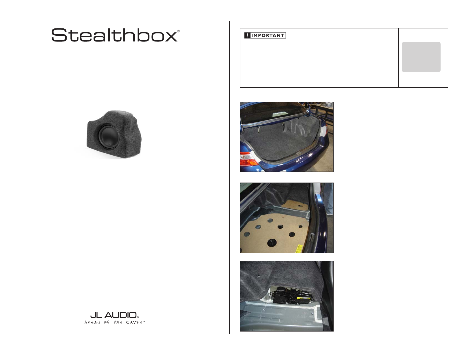
Thank you for choosing a JL Audio Stealthbox® for your automotive sound system. With proper
installation, your new vehicle-specific enclosed subwoofer system will deliver years of listening pleasure.
If you choose to perform the installation yourself, it is absolutely vital that
the Stealthbox
instructions. Failure to mount the enclosure properly presents two problems:
1) The sub-bass performance will suffer due to the movement of the enclosure
caused by the force exerted by the woofer(s).
2) A loose enclosure presents a serious safety hazard in the event of a collision
or sudden deceleration.
®
be properly mounted to the vehicle according to these
S T E P 1
Remove any contents from the trunk so that you have a
clean area to work in.
S T E P 2
Remove both of the hardboard floor inserts
INSTALLATION
D I F F I C UL T Y:
OU T
OF
35
ESTIMATED TIME:
23 HOURS
We strongly recommend that you have your new Stealthbox® installed by your authorized JL Audio
dealer. The installation professionals employed by your dealer have the necessary tools and experience
to disassemble and reassemble your vehicle properly. If you prefer to perform your own installation,
please read this installation guide completely
before beginning the process.
S T E P 3
The Jack and it’s mounting foam will be removed from the
compartment on the passengers side of the trunk floor.
Continued on Next Page
SB-T-CAM/12W3V3 INSTR_SKU# 011284
S T E P 4
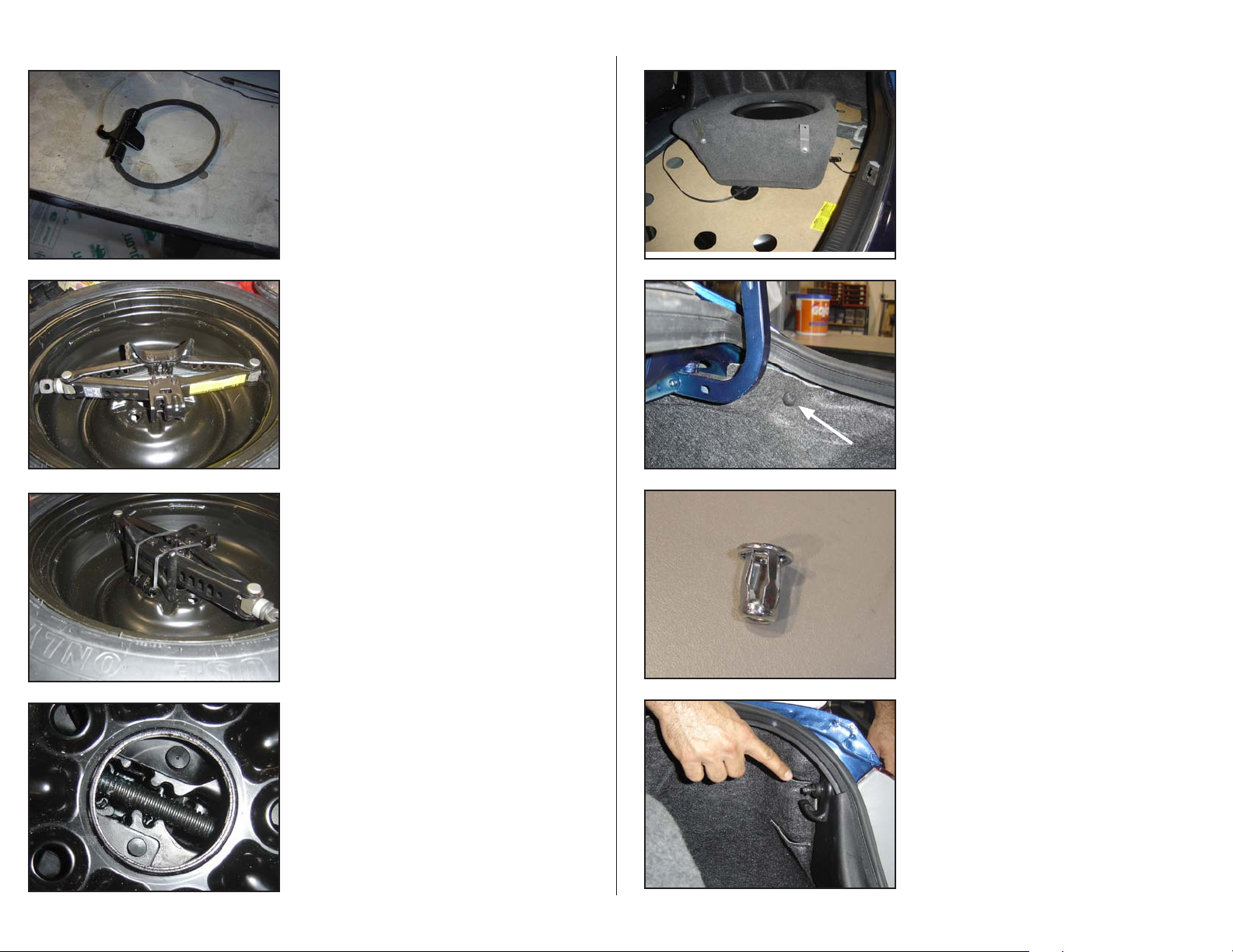
Remove the strap that secured the Jack to the locating foam,
this will be re-used to secure the jack to the spare tire.
S T E P 5
Remove the spare tire and turn it over. Put the jack inside
the wheel and, expand it so that the pressure from the jack
holds it in place.
S T E P 6
Use the strap that was removed in STEP 4 to secure the jack
to the spare wheel.
S T E P 8
Re-install both floor panels that were removed in
Install both of the brackets on the bottom of the enclosure as shown
S T E P 9
Remove the trunk liner fastening plug, this will be replaced
by one of 1/4-20 Rivet Nuts (see detailed picture of the Rivet
Nut below). Enlarge the hole using a 3/8” drill bit and, drill.
STEP 2.
*CAUTION*
Before drilling, always make sure that you are not
going to be drilling into any gas lines, brake lines,
transmission lines, electrical wiring, exhaust systems
or anything else that might cause a reduction in
your weekly pay. Always wear eye protection when
drilling.
S T E P 1 0
Insert the 1/4-20 Rivet Nut into the appropriate hole and,
expand it by tightening a 1/4-20 x 5/8” Pan Head Phillips
Screw, once the 1/4-20 Rivet Nut has been expanded in
place, remove the 1/4-20 x 5/8” Pan Head Phillips Screw. The
procedure for installing the Rivet Nuts will be repeated three
times in total
(STEPS 9 & 15) as will be detailed.
Page 2 • JL Audio, Inc 2008
S T E P 7
Align the jack so that the bolt that secures the spare can be
re-inserted thru the wheel and, jack thereby securing both in
the spare tire well.
S T E P 1 1
The anchor point for the cargo net needs to be removed for
the installation of the Stealthbox®.
Continued on Next Page

SB-T-CAM/12W3V3 INSTR_SKU# 011284
THREADED INSERT
FLAT WASHER
HEX BOLT
LOCK WASHER
MOUNTING BRACKET
LOCK WASHER
STEALTHBOX®
VEHICLE BODY
RIVET NUT
PHILLIPS HEAD SCREW
S T E P 1 2
Attach the upper mounting bracket into the just installed
1/4-20 Rivet Nut using One of the supplied 1/4-20 Phillips
Head Screws. The correct order of the hardware is indicated
in the illustration below.
S T E P 1 3
The two lower brackets from the Stealthbox® should be configured as shown, the one that goes up will be the same, just
arranged vertically.
S T E P 1 4
Press in at the bottom of the enclosure so that it sits as tight
in the side as possible, and mark the locations for the bottom
anchors to be drilled through the floor. Remove the enclosure from the side.
S T E P 1 6
Test the Stealthbox® to ensure proper operation then,
remount using the supplied three Phillips Head Screws, Split
Lock Washers and, Flat Washers.
S T E P 1 7
C O N G R A T U L A T I O N S !
You have completed the installation for this model!
Enjoy your new Stealthbox®!
Please refer to the Power Recommendation section for an
amplifier recommendation and basic set-up help.
Page 3 • JL Audio, Inc 2008
S T E P 1 5
Using a drill with a 3/8” bit, drill through the locations marked
STEP 14 . Repeat STEP 10 in both holes.
in
*CAUTION*
Before drilling, always make sure that you are not
going to be drilling into any gas lines, brake lines,
transmission lines, electrical wiring, exhaust systems
or anything else that might cause a reduction in
your weekly pay. Always wear eye protection when
drilling.
Continued on Next Page
SB-T-CAM/12W3V3 INSTR_SKU# 011284
I N C L U D E D H A R D W A R E
3) 1/4-20 Rivet Nut 3) 1/4-20 x 1” Hex Head Bolt
3) 1/4” Split Lock Washer 6) 1/4” Flat Washer
3) 1/4-20 x 5/8” Pan Head Phillips Screw
S P E C I F I C A T I O N S
Enclosure Type: Acoustic Suspension (sealed)
Driver Type: 12W3v3-4
Nominal Impedance: 4 Ohms
Continuous Power Handling: 500 Watts
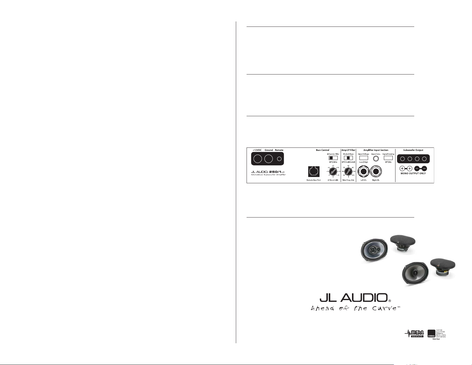
P O W E R R E C O M M E N D A T I O N
JL Audio recommends using a high quality amplifier such as the JL Audio 250/1v2.
The diagram below shows the recommended crossover, infrasonic filter and equalizer settings for the 250/1v2
when being used to power your Stealthbox®.
Page 5• JL Audio, Inc 2008
The JL Audio 250/1v2 is a very versatile audio component. Please consult the owner’s manual for even more
detailed information about installing and tuning this amplifier.
M I D / H I G H F R E Q U E N C Y D R I V E R F I T M E N T
A variety of JL Audio coaxial and component systems will fit in the factory speaker locations of you vehicle.
Front Speaker Size / Location: 6” x 9”- Front Doors
Fits JL Audio Models: TR690-TXi, C2-690tx, VR690-CXi
Rear Speaker Size / Location: 6” x 9”- Rear Door
Fits JL Audio Models: TR690-TXi, C2-690tx, VR690-CXi
(954) 443-1100
All specifications are subject to change without notice. “JL Audio®” and the JL Audio logo, “Stealthbox” and the Stealthbox logo are registered
trademarks of JL Audio, Inc. “Ahead of the Curve” and its respective logo is a trademark of JL Audio, Inc.
JLA-SKU# 011284 ©12-10-2008 • Printed in USA • ©2008 JL Audio, Inc. • U.S. PATENTS: #5,734,734 #5,949,898 #6,118,884 #6,229,902
#6,243,479 #6,294,959 #6,501,844 #6,496,590 #6,441,685 #5,687,247 #6,219,431 #6,625,292 #D472,891 #D480,709 Other U.S. & Foreign
patents pending. For more detailed information please visit us online at www.jlaudio.com.
1 0 3 6 9 N O R T H C O M M E R C E P A R K W A Y • M I R A M A R , F L O R I D A • 3 3 0 2 5 • U S A
w w w. j l a u d i o . c o m
 Loading...