

Page 1

SB-SMRT-4-2/8W3V3 INSTR_SKU# 011288
I N S T A L L A T I O N G U I D E
for the
SB-SMRT-4-2/8W3v3
SKU#94448
2008+
Thank you for choosing a JL Audio Stealthbox® for your automotive sound system. With proper
installation, your new vehicle-specific enclosed subwoofer system will deliver years of listening pleasure.
We strongly recommend that you have your new Stealthbox® installed by your authorized JL Audio
dealer. The installation professionals employed by your dealer have the necessary tools and experience
to disassemble and reassemble your vehicle properly. If you prefer to perform your own installation,
please read this installation guide completely
before beginning the process.
If you choose to perform the installation yourself, it is absolutely vital that
the Stealthbox
instructions. Failure to mount the enclosure properly presents two problems:
1) The sub-bass performance will suffer due to the movement of the enclosure
caused by the force exerted by the woofer(s).
2) A loose enclosure presents a serious safety hazard in the event of a collision
or sudden deceleration.
®
be properly mounted to the vehicle according to these
S T E P 1
Read all of the instructions through once before starting the
work. We know you’ve seen this warning before but, if
you only follow each step as it comes, the progression
won’t make sense, if you read everything all the way
through, you’ll understand, the job will be easier.
Clean out the passengers side of the vehicle so that you have
a comfortable place to work.
S T E P 2
Remove the carpeting and, the foam underlayment as if
you were accessing the battery (refer to the vehicles owners
manual if neccessary).
INSTALLATION
D I F F I C UL T Y:
OU T
OF
45
ESTIMATED TIME:
3 HOURS
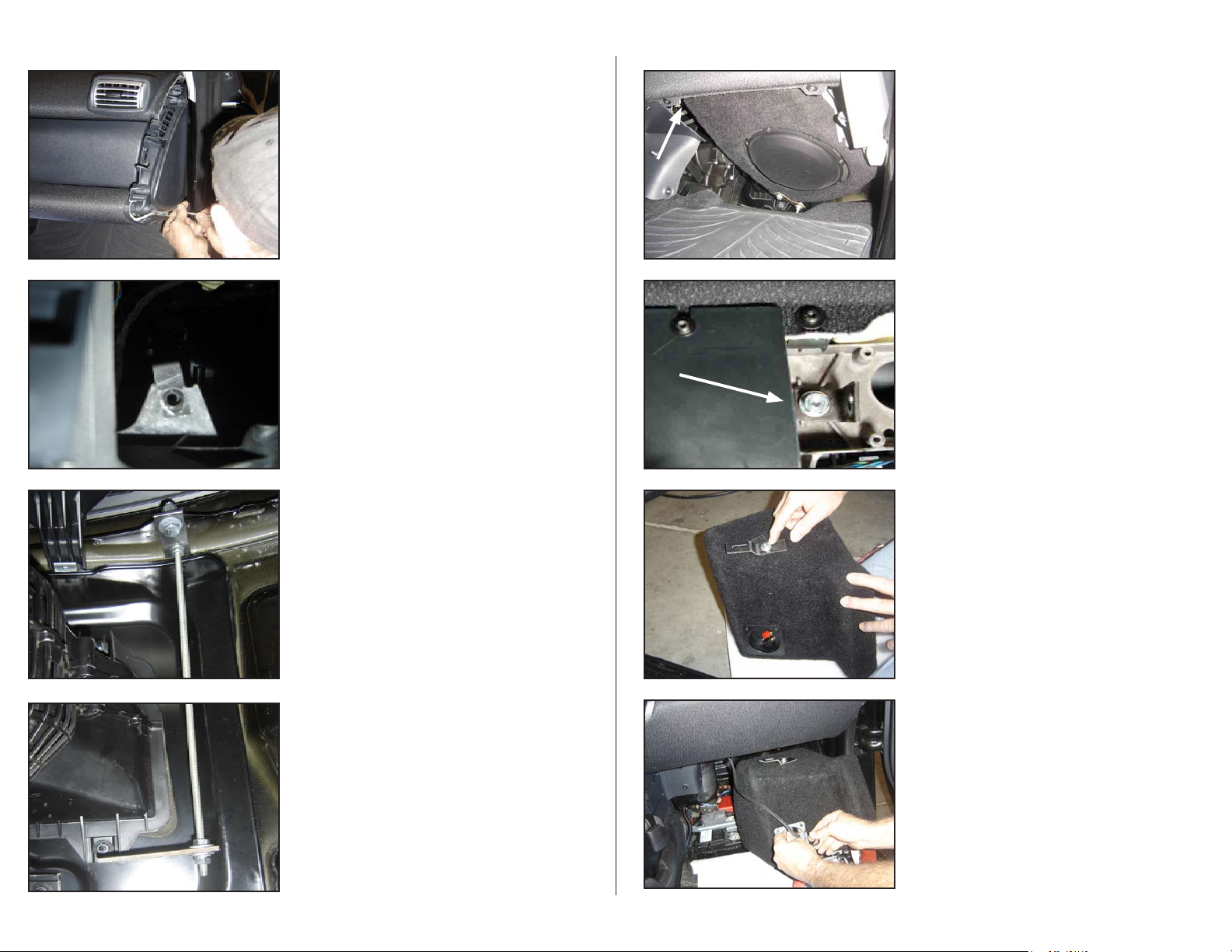
S T E P 3
Under the passengers end of the dash there is a Torx screw
that holds the dash end trim panel in place, remove it and,
the trim piece.
Continued on Next Page
Page 2
SB-SMRT-4-2/8W3V3 INSTR_SKU# 011288
S T E P 4
Once the trim piece is removed, there are three Torx screws
that hold the dash end piece in place, remove those and the
end piece.
S T E P 5
Looking into the end of the dash, you will notice the
aluminum extrusion that is the frame of the dash. There is an
exposed slot, slide the included 1/4-20 Speed Clip over this
notch as shown.
S T E P 6
Looking from under the dash, near the front of the vehicle,
there is a flange just under the top of the dash that has a
factory hole . Assemble the included Top Bracket and,
1/4-20 All Threaded Rod by putting on a 1/4-20 Nut and,
Split Lockwasher then threading the rod into the bracket so
that just a few threads come out on the top side. Tighten the
1/4-20 Nut and, Split Lockwasher to the Top Bracket. Once
the Top Bracket/ All Threaded Rod have been assembled,
bolt the other end of the Top Bracket to the flange using the
included 3/8-16 x 1” Hex Head Bolt, Nut, Washers and, Split
Lock Washer then rotate the Bracket so that it rests on the
top of AC system as shown, tighten down all of this hadware.
S T E P 8
This picture is only to illustrate where the DETAIL below is
located, the enclosure and, woofer have NOT been mounted
yet. Where the arrow is pointing is where the DETAIL below
is located.
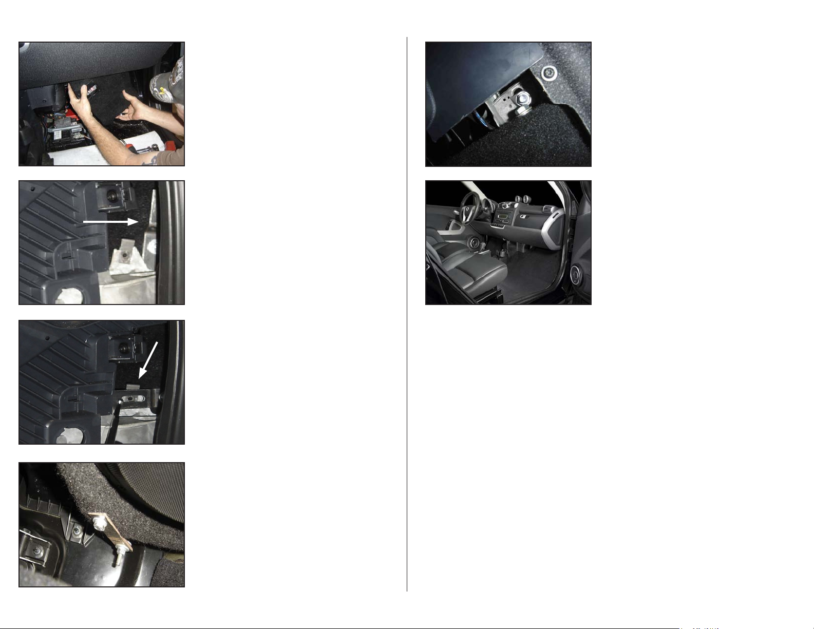
D E T A I L
Install the included right angle bracket as shown through
the slot in the dash extrusion using the included
3/8-20 Nut, Washers, 3/8-16 x 1 1/2” Hex Head Bolt, and,
Split Lockwasher. the end with the hole closest to the bend
is against the dash extrusion. Slide the bracket all the way
towards the center of the vehicle, oriented as shown.
DO NOT TIGHTEN THIS ASSEMBLY YET!
S T E P 9
Remove the woofer from the enclosure. Mount the
Elevated Bracket to the Stealthbox® as shown with the
slotted end exposed and pointing towards the top of the
enclosure, using the included 1/4-20 x 1” Hex Head Bolt, Split
Lockwasher and Washer. Snug this hardware down so that it
isn’t loose but,
DO NOT TIGHTEN THIS ASSEMBLY YET!
Page 2 • JL Audio, Inc 2009
S T E P 7
On the Bottom end of the 1/4-20 All Threaded Rod, install
the Bottom Bracket as shown (approximately 1- 1 1/4” from
the bottom), using included 1/4-20 Nuts, Washers and, Split
Lock Washer.
DO NOT TIGHTEN THIS ASSEMBLY YET!
S T E P 1 0
Attach the wire from the amplifier to the terminals on the
Stealthbox®
Continued on Next Page
Page 3
SB-SMRT-4-2/8W3V3 INSTR_SKU# 011288
S T E P 1 1
Slide the enclosure up into place, it’s a tight fit and, you’ll
need to move it around a little but if you start as shown, it
will go in without any problems.
S T E P 1 2
Looking at the end of the dash, you should see the Elevated
Bracket pointing up next to the previously installed Speed
Clip. (See Arrow)
S T E P 1 3
Rotate the Elevated Bracket so that the slotted end is over
the Speed Clip (as shown) and, install the included
1/4-20 x 1” Hex Head Bolt, Split Lockwasher and Washer.
S T E P 1 5
Install the included, 3/8-16 x 1” Hex Head Bolt, Split
Lockwasher and Washer through the Right Angle Bracket
installed in STEP 8 into the Stealthbox® as shown.
NOW YOU NEED TO TIGHTEN ALL OF THE PREVIOUSLY
INSTALLED HARDWARE!
Re-install the woofer into the enclosure.
Re-assemble the end of the dash in the reverse order that
it was disassembled, re-install the Foam Underlayment and
the Carpet.
S T E P 1 6
C O N G R A T U L A T I O N S !
You have completed the installation for this model!
Enjoy your new Stealthbox®!
Please refer to the Power Recommendation section for an
amplifier recommendation and basic set-up help.
Page 3 • JL Audio, Inc 2009
DO NOT TIGHTEN THIS ASSEMBLY YET!
S T E P 1 4
Rotate the Bottom Bracket on the 1/4-20 All Threaded Rod
so that it lines up with the threaded insert in the Stealthbox®,
you may need to raise or lower the position of the Bottom
Bracket on the All Threaded Rod in order to align everything.
Install the included 3/8-16 x 1” Hex Head Bolt, Split Lock
Washer and Washer as shown, securing the Stealthbox® via
it’s Threaded insert to the Threaded Rod.
DO NOT TIGHTEN THIS ASSEMBLY YET!
Continued on Next Page
Page 4
SB-SMRT-4-2/8W3V3 INSTR_SKU# 011288
I N C L U D E D H A R D W A R E
6) 1/4” Split Lock Washer 5) 1/4” Flat Washer
1/4-20 Hex Nut 3) 1/4-20 x 1” Hex Head Bolt
3)
1) 1/4-20 Speed Clip 1) 1/4-20 x 12” All Threaded Rod
5) 3/8” Flat Washer 2) 3/8-16 x 1” Hex Head Bolt
3)
3/8” Split Lock Washer 1) 3/8-16 x 1 1/2” Hex Head Bolt
2) 3/8-16 Hex Nut 4) Custom Brackets
S P E C I F I C A T I O N S
Enclosure Type: Acoustic Suspension (sealed)
Driver Type: 8W3v3-4
Nominal Impedance: 4 Ohms
Continuous Power Handling: 250 Watts
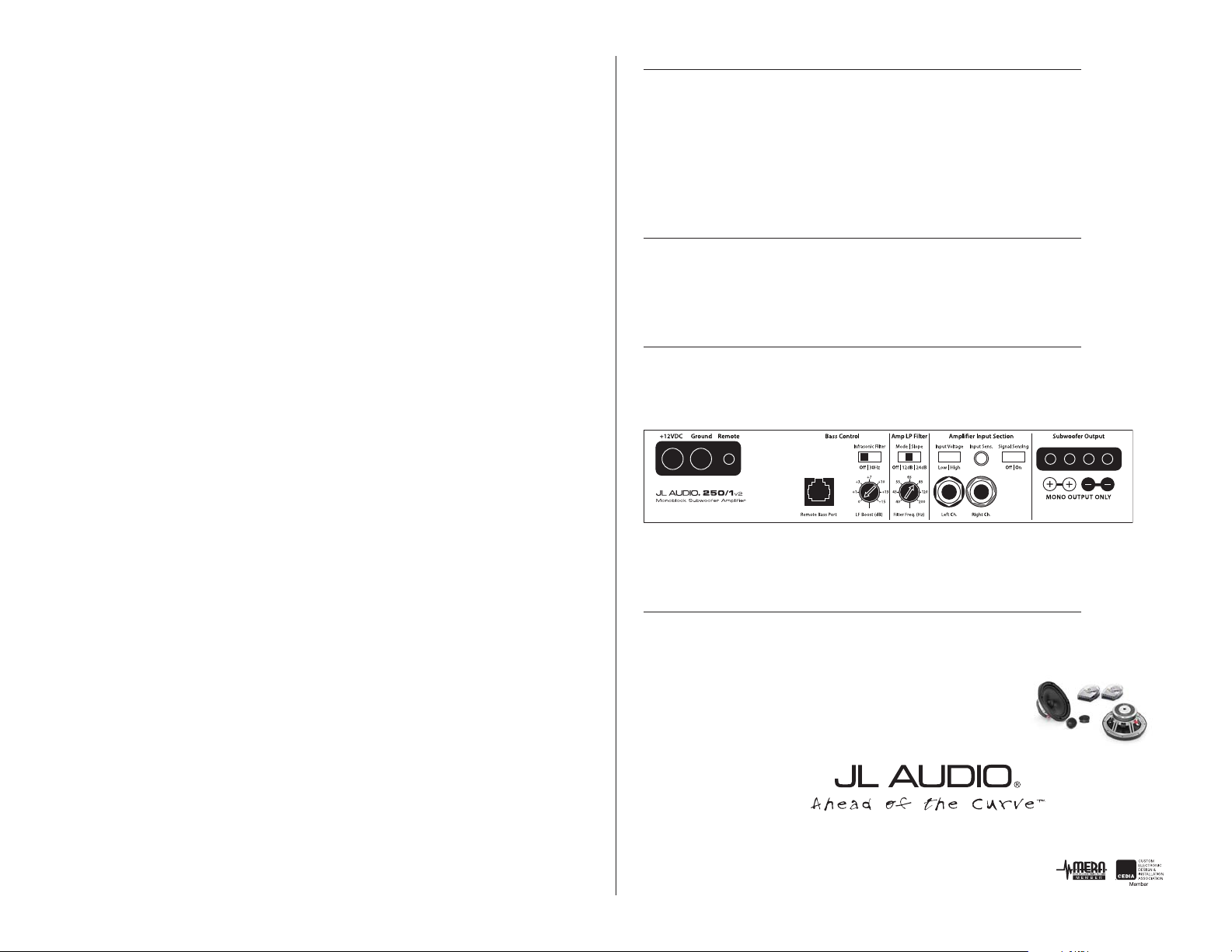
P O W E R R E C O M M E N D A T I O N
JL Audio recommends using a high quality amplifier such as the JL Audio 250/1v2.
The diagram below shows the recommended crossover, infrasonic filter and equalizer settings for the 250/1v2
when being used to power your Stealthbox®.
Page 5• JL Audio, Inc 2009
The JL Audio 250/1v2 is a very versatile audio component. Please consult the owner’s manual for even more
detailed information about installing and tuning this amplifier.
M I D / H I G H F R E Q U E N C Y D R I V E R F I T M E N T
A variety of JL Audio coaxial and component systems will fit in the factory speaker locations of you vehicle.
Front Speaker Size / Location: 6.0”- Front Doors
Fits JL Audio Models: C2-650, C2-650x
To change the OEM front speakers requires extensive
modication and, the use of spacers/adaptors.
(954) 443-1100
All specifications are subject to change without notice. “JL Audio®” and the JL Audio logo, “Stealthbox” and the Stealthbox logo are registered
trademarks of JL Audio, Inc. “Ahead of the Curve” and its respective logo is a trademark of JL Audio, Inc.
JLA-SKU# 011288 03-26-2009 • Printed in USA • ©2008 JL Audio, Inc. • U.S. PATENTS: #5,734,734 #5,949,898 #6,118,884 #6,229,902 #6,243,479
#6,294,959 #6,501,844 #6,496,590 #6,441,685 #5,687,247 #6,219,431 #6,625,292 #D472,891 #D480,709 Other U.S. & Foreign patents pending.
For more detailed information please visit us online at www.jlaudio.com.
1 0 3 6 9 N O R T H C O M M E R C E P A R K W A Y • M I R A M A R , F L O R I D A • 3 3 0 2 5 • U S A
w w w. j l a u d i o . c o m
 Loading...