

Page 1
SB-SC-TC/10W3v3
2005 - Up
Scion tC
SB-SC-TC/10W3v3_INSTR_SKU#01124
SB-SC-TC/10W3v3_INSTR_SKU#01124
2
INSTALLATION GUIDE
for the
SB-SC-TC/10W3v3
2005 - Up
Thank you for choosing a JL Audio Stealthbox® for your automotive sound system. With proper
installation, your new vehicle-specific enclosed subwoofer system will deliver years of listening pleasure.
Scion tC
If you choose to perform the installation yourself, it is absolutely vital that
the Stealthbox
instructions. Failure to mount the enclosure properly presents two problems:
1) The sub-bass performance will suffer due to the movement of the enclosure
caused by the force exerted by the woofer(s).
2) A loose enclosure presents a serious safety hazard in the event of a collision
or sudden deceleration.
Grommet
®
be properly mounted to the vehicle according to these
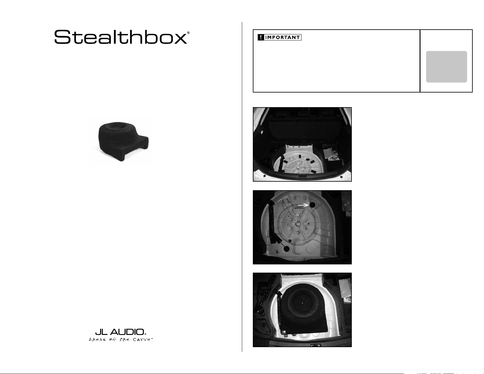
STEP 1
Place the rears seats in the upright position.
Remove the factory cargo cover, carpeted flooring, jack tools
and the spare tire.
STEP 2
Remove the black foam blocks and the large round rubber
grommet from the spare tire wheel.
INSTALLATION
DIFFICULTY:
OUT
OF
5
We strongly recommend that you have your new Stealthbox® installed by your authorized JL Audio
dealer. The installation professionals employed by your dealer have the necessary tools and experience
to disassemble and reassemble your vehicle properly. Also, keep in mind that your warranty coverage
extends to 1 year if your system is installed or approved by your authorized JL Audio dealer. If you
prefer to perform your own installation, please read this installation guide completely
before beginning the process.
STEP 3
Place the Stealthbox® into the spare tire wheel. The flat end
of the Stealthbox® is to face the back of the vehicle.
Continued on Next Page
Page 2
SB-SC-TC/10W3v3_INSTR_SKU#01124
SB-SC-TC/10W3v3_INSTR_SKU#01124
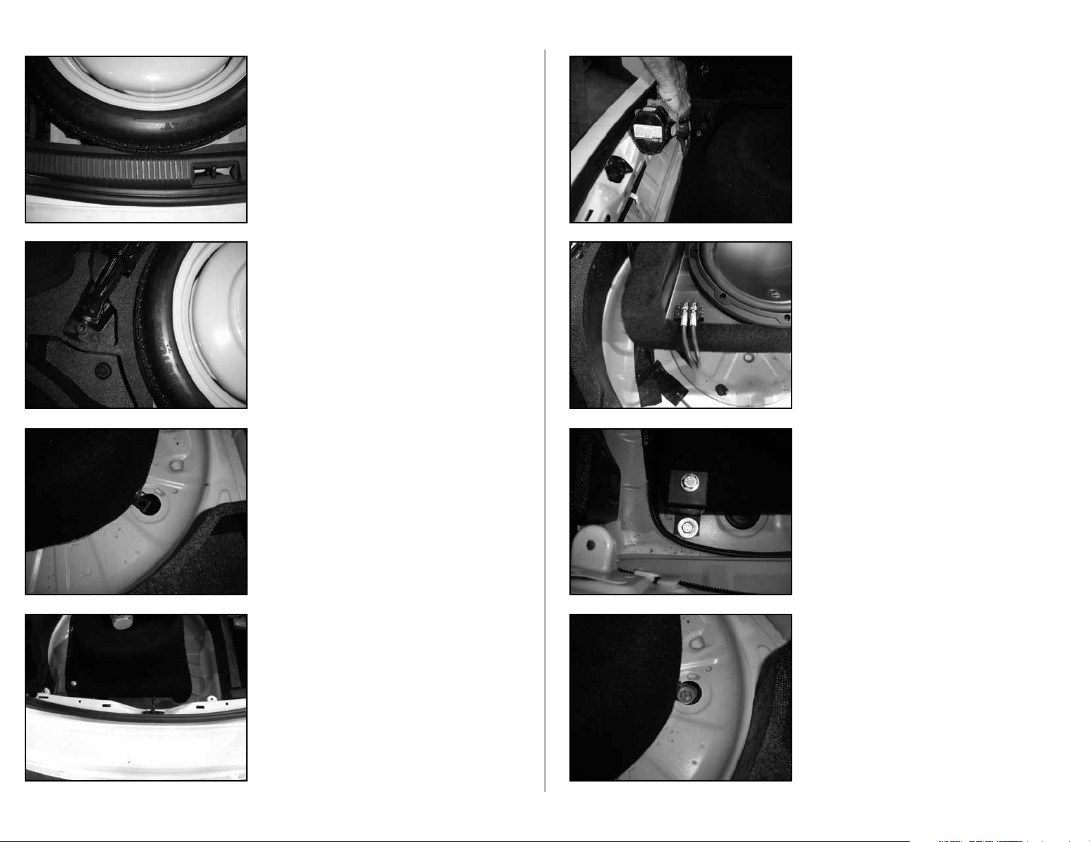
STEP 4
Place t h e spar e t ire on t o the Stealth box®, with the yellow
side up.
Position the spare tire a n d S tealthbox® so the sp are ti re is
match es up wi th the curve of the rear sill p l ate.
STEP 5
Position the spare tire and Stealthbox® so the spare tire
matches up with the curve of the left side foam panel.
STEP 6
Make sure that the front L-bracket’s mounting hole is
positioned over the hole from the removed grommet.
STEP 8
Note: Bef or e dr il li n g, m a ke su re t h at yo u ar e no t go in g
to be drilling into any gas lines, brake lines, transmission
lines, electrical wiring or any thing else that might cause
a reduc ti on i n you r we ek l y p ay.
Always wear eye protection when drilling!
Wit h a drill and a 3 /8 -inch d rill bit, us ing the rear L-bracket ’s
mounting hole as a gu i de. Drill throug h the veh i c l e ’s wheel
well.
STEP 9
Lay the Stealthbox® onto it’s top side.
Run sp eaker w i re fro m the am p l ifi er loca tion to t h e
Stealthbox
®
loca t ion, apply sp a d e f orks onto t h e speak er
wire, secu re to the t erminal an d c h eck for proper o peration
of the woofer.
STEP 10
Lay th e S t ealt hbox® b ack to it’s ori ginal p o s itio n.
Appl y a supplied f lat wa sher on t o a supplied hex c ap scre w.
Page 2 • JL Audio, Inc 2006
STEP 7
Remove the spare tire without disturbing the Stealthbox®.
Remove the rear sill plate from vehicle.
Inse rt t his bol t asse mbly th rough the rear Z-bracket and the
drilled hole.
STEP 11
Appl y a supplied f lat wa sher on t o a supplied hex c ap scre w.
Drop this bo lt ass embly throu gh the front L-br a c k et and
larg e fact ory h o le.
Continued on Next Page
Page 3

SB-SC-TC/10W3v3_INSTR_SKU#01124
SB-SC-TC/10W3v3_INSTR_SKU#01124
JLA-SKU#011224-11-28-200
(4)
3/8-inch USS Flat Washer
(1)
4-inch x 6-inch x 3/16-inch Aluminum Plate
(2)
3/8-inch Split Lock Washer
(2)
3/8-inch -16 Hex Nut
(4)
3/8-inch x 1-1/4-inch Fender Washer
(2)
Foam Flooring Spacers
(2)
3/8-inch x 1-3/4-inch -16 Hex Cap Screws
(1)
Carpeted Flooring
Acoustic Suspension (sealed)
10W3v3-4
4 ohms mono
300 Watts
6.5-inch Separates / Front Doors
TR650-CSi, TR650-CXi, VR650-CSi, VR650-CXi, XR650-CSi, XR650-CXi & ZR650-CSi
5.25-inch / Rear Deck
TR525-CXi, VR525-CXi & XR525-CXi
BRACKET FROM STEALTHBOX
VEHICLE'S FLOOR
ALUMINUM PLATE(front bolt assmebly only)
FLAT WASHER
HEX NUT
HEX HEAD BOLT
FLAT WASHER
FENDER WASHER
LOCK WASHER
STEP 12
Apply a bead of silicon or any adhesive se alant around the
hole of the supplied aluminum plate.
STEP 13
From under the vehicle, place the s upplied aluminum
plate(front bolt assembly only), fender washers, flat washers,
lock washers an d then hex nuts onto each protru ding he x
cap screws and secure.
Note: For adde d p rot e c t io n, i t i s re co mm e nd ed t h at
you appl y a be ad o f si li co ne b e t we e n t he ve hi c le a nd
the fen de r w a sh e r. Aft e r th e b ol t a ss e mb l y is t i gh t ly
secured, it is also recomme nded th at vehicle und ercoatin g m at e ri a l is a p pl ie d t o t he e x po se d a ss e mb l y.
STEP 14
Place both supplied foam supports around the spare tire as
shown to the left.
INCLUDED HARDWARE
(4)
3/8-inch USS Flat Washer
(2)
3/8-inch Split Lock Washer
(4)
3/8-inch x 1-1/4-inch Fender Washer
(2)
3/8-inch x 1-3/4-inch -16 Hex Cap Screws
(1)
4-inch x 6-inch x 3/16-inch Aluminum Plate
(2)
3/8-inch -16 Hex Nut
(2)
Foam Flooring Spacers
(1)
Carpeted Flooring
SPECIFICATIONS
Enclosure Type:
Driver Type:
Nominal Impedance:
Continuous Power Handling:
Acoustic Suspension (sealed)
10W 3v3- 4
4 ohms mono
300 Watts
POWER RECOMMENDATION
JL Audio recommends using a high quality amplifier such as the JL Audio 250/1.
The diagram below shows the recommended crossover, infrasonic filter and equalizer settings for the 250/1 when
being used to power your Stealthbox®.
+12VDC Ground Remote
JL AUDIO 250/1
monoblock subwoofer amplifier
Preamp Output Section
Output Mode
Full-Range/Low-Pass/High-Pass
Left Ch.
Right Ch.
Bass Control
Infrasonic Filter
Off/30Hz
+7
+3
+1
LF Boost (dB)
+10
+13
Amp LP Filter
Mode/Slope
Off/12dB/24dB
Filter Freq. (Hz)
Amplifier Input Section
Input Voltage
Low/High
Left Ch.
Input Sens.
Right Ch.
Signal Sensing
Off/On
The JL Audio 250/1 is a very versatile audio component. Please consult the owner’s manual for even more
detailed information about installing and tuning this amplifier.
Page 3 • JL Audio, Inc 2006
Place the spare tire with the yellow side up onto the
Stealthbox® and secure with the factory hold down bolt that
was removed in STEP 1.
Place the supplied replacement flooring into vehicle.
Note: If th e c hi ld LATCH syste m wi ll b e u se d , sl ig ht
modification of the supplied flooring is required.
CONGRATULATIONS
You have completed the installation for this model!
Please refer to the Power Recommendation section for an
amplifier recommendation and basic set-up help.
MID/HIGH FREQUENCY DRIVER FITMENT
A variety of JL Audio coaxial and component systems will fit in the factory speaker locations of you vehicle.
Front Speaker Size / Location:
Fits JL Audio Models:
Rear Speaker Size / Location:
Fits JL Audio Models:
All specifications are subject to change without notice. “JL Audio®” and the JL Audio logo, “Stealthbox” and the Stealthbox logo are registered
trademarks of JL Audio, Inc. “Ahead of the Curve” and its respective logo is a trademark of JL Audio, Inc.
JLA-SKU#011224-11-28-20066 • Printed in USA • ©2005 JL Audio, Inc. • U.S. PATENTS: #5,734,734 #5,949,898 #6,118,884 #6,229,902
#6,243,479 #6,294,959 #6,501,844 #6,496,590 #6,441,685 #5,687,247 #6,219,431 #6,625,292 #D472,891 #D480,709 Other U.S. & Foreign
patents pending. For more detailed information please visit us online at www.jlaudio.com.
10369 NORTH COMMERCE PARKWAY • MIRAMAR, FLORIDA • 33025 • USA
6.5-inch Separates / Front Doors
TR650-CSi, TR650-CXi, VR650-CSi, VR650-CXi, XR650-CSi, XR650-CXi & ZR650-CSi
5.25-inch / Rear Deck
TR525-CXi, VR525-CXi & XR525-CXi
(954) 443-1100
www.jlaudio.com
 Loading...