

Page 1
SB-P-CYNNE/10W6v2/BK
2003 - 2006
Porsche Cayenne
SB-P-CYNNE/10W6v2/BK_INSTR_SKU#011231
SB-P-CYNNE/10W6v2/BK_INSTR _SKU#011231
3
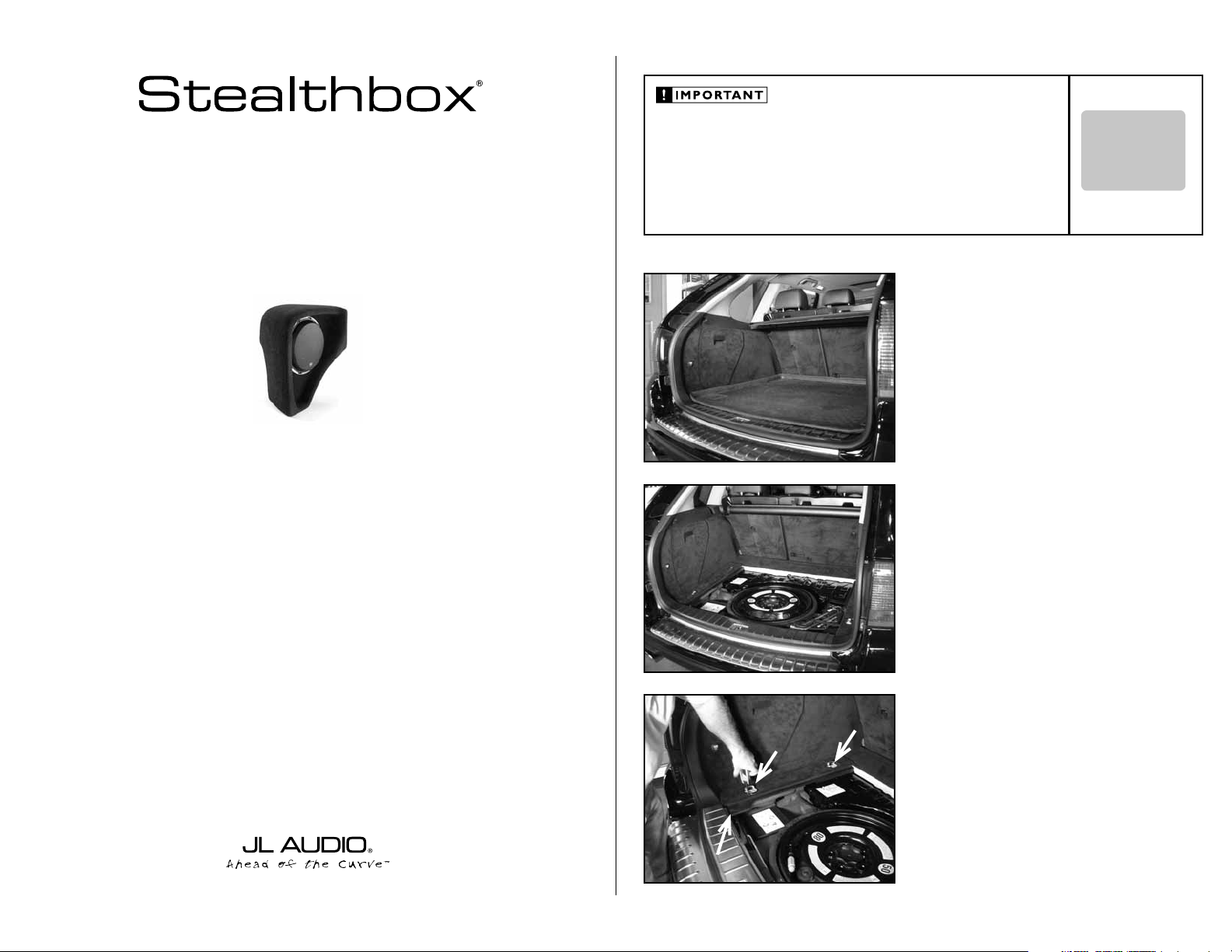
INSTALLATION GUIDE
for the
SB-P-CYNNE/10W6v2/BK
2003 - 2006
Thank you for choosing a JL Audio Stealthbox® for your automotive sound system. With proper
installation, your new vehicle-specific enclosed subwoofer system will deliver years of listening pleasure.
Porsche Cayenne
If you choose to perform the installation yourself, it is absolutely vital that
the Stealthbox
instructions. Failure to mount the enclosure properly presents two problems:
1) The sub-bass performance will suffer due to the movement of the enclosure
caused by the force exerted by the woofer(s).
2) A loose enclosure presents a serious safety hazard in the event of a collision
or sudden deceleration.
®
be properly mounted to the vehicle according to these
STEP 1
Remove any contents from the cargo area.
STEP 2
Remove the flooring.
INSTALLATION
DIFFICULTY:
OUT
OF
5
ESTIMATED TIME:
23 HOURS
We strongly recommend that you have your new Stealthbox® installed by your authorized JL Audio
dealer. The installation professionals employed by your dealer have the necessary tools and experience
to disassemble and reassemble your vehicle properly. Also, keep in mind that your warranty coverage
extends to 1 year if your system is installed or approved by your authorized JL Audio dealer. If you
prefer to perform your own installation, please read this installation guide completely
before beginning the process.
STEP 3
A
A
B
With a T-30 wrench or socket, remove the pair of hold down
cleats(A).
With an 10mm socket, remove the bolt(B) that secures the
side panel to the vehicle.
Continued on Next Page
Page 2
SB-P-CYNNE/10W6v2/BK_INSTR_SKU#011231
SB-P-CYNNE/10W6v2/BK_INSTR _SKU#011231
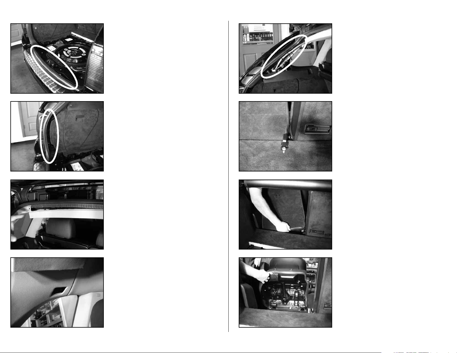
STEP 4
Remove the bottom sill plate.
STEP 5
Remove the lower d-pillar trim.
STEP 6
Remove the top sill plate.
STEP 8
Remove the upp er d-p i llar trim.
STEP 9
Wit h a T-30 sock et, r emove th e b olt and meta l brac k et that
is located be twee n the two rear seats.
STEP 10
Grab a hold of the back of the driver’s side rear seat as in
the picture.
Lift the right s i de of the seat up and out of t he hinge
bracket.
Pull the left side of the seat towards the middle of the
vehic l e, slid ing the s e at off of a h inge pin.
Once th e seat is off bot h h inge poi n ts, remove t h e seat
from the vehicl e.
Page 2 • JL Audio, Inc 2007
STEP 7
Remove the plastic cover from the upper d-pillar trim.
Remove the phillip head screw that has been exposed .
STEP 11
Flip the driver’s side rear bottom cushion towards the front
of the vehicle.
Continued on Next Page
Page 3
SB-P-CYNNE/10W6v2/BK_INSTR_SKU#011231
SB-P-CYNNE/10W6v2/BK_INSTR _SKU#011231
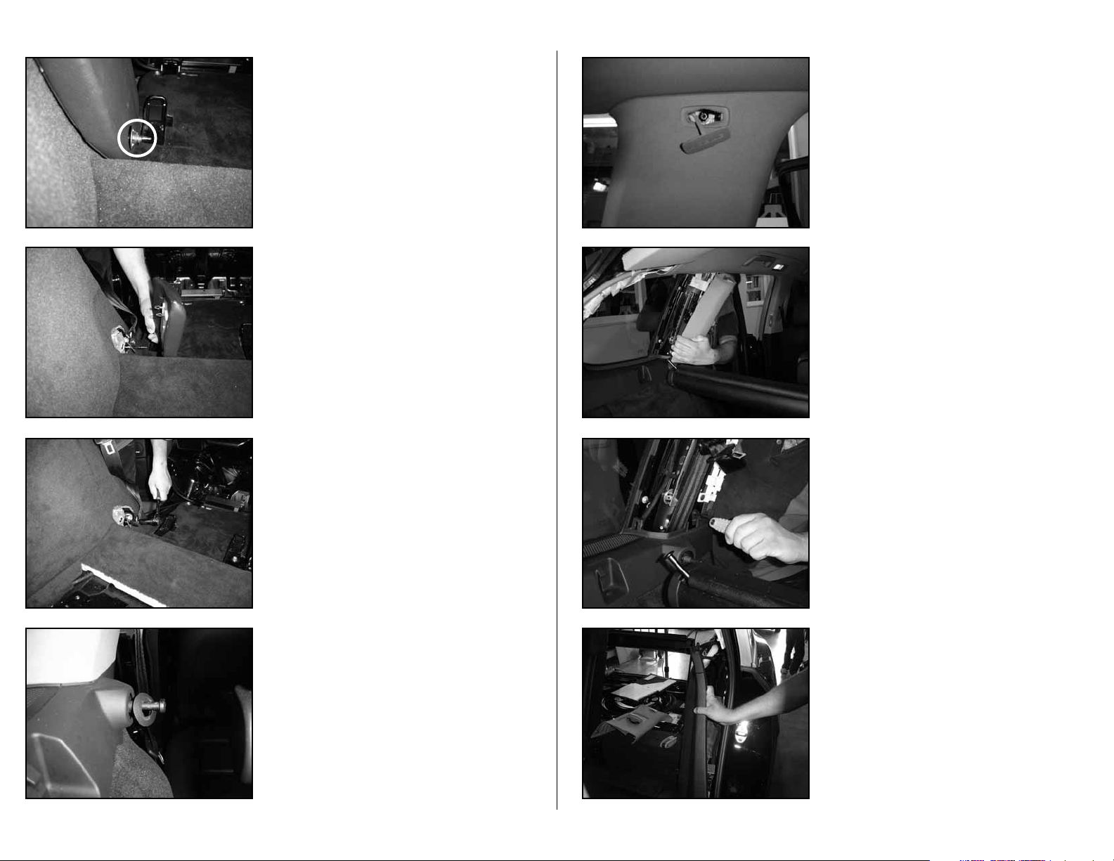
STEP 12
Remove the plastic collar that is around the hinge pin.
STEP 13
Remove the trim panel.
STEP 14
With a 17mm socket and ratchet, remove the seat belt
retracting unit.
STEP 16
Pull the SRS p lastic badg e from t h e upper c-pi l lar trim.
Wit h a T-25 soc k et, r emove th e bolt that has been
exposed.
STEP 17
An airbag is l o cated b ehind the c-pilla r trim. Use ca ution
while removing this panel. All wiring/connections should be
protected.
As in the illustratio n, rea c h around to the rear of the c-pillar
trim and carefully remove the c-pillar trim from the c-pillar,
by pulli ng towards you .
STEP 18
With a T-25 socket remove the bolt that secures the front
of the si de trim pane l t o the c-pillar.
Page 3 • JL Audio, Inc 2007
STEP 15
Remove the plastic ring from the rear seat’s upper latch pin.
STEP 19
From the driver’s side rear door opening. Pull the front of the
cargo side trim panel from the vehicle’s body. Do not fully
remove this side trim panel at this time.
Continued on Next Page
Page 4

SB-P-CYNNE/10W6v2/BK_INSTR_SKU#011231
SB-P-CYNNE/10W6v2/BK_INSTR _SKU#011231
STEP 20
Wit h a T-25 soc k et, r emove th ree bolts that secures t h i s
rear side trim panel.
STEP 21
Pull the rest of the side trim panel from the body of the
vehicle.
Once the side trim panel is loose, disconnect the power
outlet 12V plug from the wire harness.
STEP 22
Pull the side trim panel out of vehicle.
STEP 24
Found i n the re armo st dr iver’s side floor corner, remove
the rubber grommet in the cargo area.
Unsec ure th e wire harne ss from the wheel well.
*Ma k e sure th e ignition is not turned o n*
Loose n the bolt that s ecure s the bro wn wir e s t o the
flooring of the vehicle.
Once loose, turn this wire assembly counter clockwise until
the wi res ar e rout ed as ill u strated i n the pictur e. Secure th e
bolt.
STEP 25
Place the supp l ied top mount pl a te into po s ition. The p l ate
will on ly fit one way. T he hole in the mou nting p l ate will l ine
up with the acce ss hole from the removed grommet.
STEP 26
Run sp eaker w i re fro m the am p l ifi er’s locatio n t o the
Stealthbox
®
loca t ion and check for p roper operatio n o f
the woofer.
Page 4 • JL Audio, Inc 2007
STEP 23
With a T-30 socket, remove the bolts that secure the pocket
to the body of the vehicle.
STEP 27
Thread in one of the supplied socket cup set screws into the
bottom of the Stealthbox®, leaving 1-inch exposed.
Continued on Next Page
Page 5

SB-P-CYNNE/10W6v2/BK_INSTR_SKU#011231
SB-P-CYNNE/10W6v2/BK_INSTR _SKU#011231
STEP 28
Fully threa d the sup plied coupler t o the f irs t socket c u p set
screw from STEP 27.
Thr e a d the seco nd supplied soc k et cup se t s c rew int o the
coupler.
STEP 29
Place t h e S tealthbox® into position by guiding the socket
cup set screw assembly th rough the hol e i n the top
mounting plate instal l ed in STEP 25.
The bottom of the Stealthbox® will not touch the mounting
plate. The coupler will be touching the mounting plate.
STEP 30
Once the Stealthbox® is in position, place the supplied piece
of black carpeting between the Stealthbox® and the rear side
of the wheel well. You need to cover the corner of the wheel
well just in front of the Stealthbox®.
STEALTHBOX WALL
TOP MOUNTING PLATE
BOTTOM MOUNTING PLATE
LOCK WASHER
THREADED INSERT
SOCKET CUP SET SCREW
COUPLER
VEHICLE SHEET METAL
FLAT WASHER
SOCKET CUP SET SCREW
HEX BOLT
STEP 32
Wit h a 9/16-inch socket and the rem aining s uppli e d p air of
bolt asse m blies, secure the L-bracket t o the Stealth box®.
STEP 33
From under the vehicle, place the s upplied mounting plate,
flat washers, lock washers and then hex nut onto the
protruding socket cup set screw. Using an 9/16-i nch socket,
secure this bottom mounting assembly.
Note: For adde d p rot e c t io n, i t i s re co mm en de d t h at
you appl y a be ad o f si li co ne b e t we e n t he ve hi c le a nd
the mou nt i ng p l at e . A f t e r t he b ol t a s se mb l y is t i gh t l y
secured, it is also recomme nded th at vehicle und ercoatin g m at e ri a l is a p pl ie d t o t he e x po se d a ss e mb l y.
STEP 34
Place the factory side trim panel, removed in ST EP 22, b a c k
into place.
Page 5 • JL Audio, Inc 2007
STEP 31
Place a supplied 3/8-inch lock washer and then a supplied
flat washer onto the supplied 3/8-inch bolts.
Place two of these mounting bolt assemblies through the
supplied L-bracket. The L-bracket can only be posistioned
one way. Line up the mounting holes of the L-bracket to the
threaded inserts of the Stealthbox®.
Place the L-bracket into the mounting position and guide the
bolt assemblies through the two holes in the metal lip, as
seen in the picture to the left.
Place a supplied flat washer and supplied hex nut onto each
protruding bolt, behind the metal lip.
With an 9/16-inch box end wrench holding the nuts, use a
9/16-inch socket to secure the L-bracket to the metal lip.
STEP 35
Reconnect the power outlet 12V plug to the wire harness,
unplugged in STEP 22.
Continued on Next Page
Page 6

SB-P-CYNNE/10W6v2/BK_INSTR_SKU#011231
SB-P-CYNNE/10W6v2/BK_INSTR _SKU#011231
STEP 36
Wit h a T-25 soc k et, se c ure th e rear of t he side t rim pa nel
to the d -pillar, from STEP 20.
STEP 37
Wit h a T-25 soc k et, se c ure th e front o f the sid e trim panel
to the c-pil l ar, from STEP 18.
STEP 38
With a 17mm socket, secure the seat belt retracting unit,
from STEP 14.
STEP 40
Wit h a T-25 soc k et, se c ure th e t o p c-pillar t rim to the
c-pillar, from STE PS 16 & 17.
STEP 41
Secure the u pper d-pill a r trim t o the d- pillar, sec u re the t rim
wit h the mou n ting screw that was remove d and rep alce the
plastic cover, from ST EPS 7 & 8.
STEP 42
Replace the top sill plate, from STEP 6.
Page 6 • JL Audio, Inc 2007
STEP 39
Replace the trim an d the plasti c co l lar tha t g oes around th e
hinge p i n, fro m STEP 12 & 13.
STEP 43
Replace the low er d-p i l l ar trim, fr om STE P 5.
Continued on Next Page
Page 7

SB-P-CYNNE/10W6v2/BK_INSTR_SKU#011231
SB-P-CYNNE/10W6v2/BK_INSTR _SKU#011231
JLA-SKU#011231-04-23-200
(2)
3/8-inch -16 x 2 1/4-inch Socket Cup Set Screws
(7)
3/8-inch Flat Washer
(1)
3/8-inch -16 Socket Cup Set Screw Coupler
(5)
3/8-inch Lock Washer
(1)
Aluminum Top Mounting Plate
(4)
3/8-inch -16 x 1 1/4-inch Hex Bolts
(1)
Aluminum Bottom Mounting Plate
(3)
3/8-inch -16 Hex Nuts
Acoustic Suspension (sealed)
10W6v2-D4
2 ohms mono
400 Watts
6.5-inch / Front Doors
TR650-CXi, VR650-CSi, VR650-CXi, XR650-CSi, XR650-CXi,
C5-650, C5-650x & ZR650-CSi
6.5-inch / Rear Doors
TR650-CXi, VR
650
-CXi, C5-650x & XR
650
-CXi
STEP 44
INCLUDED HARDWARE
Replace the cargo door sill plate, from STEP 4.
(2)
3/8-inch -16 x 2 1/4-inch Socket Cup Set Screws
(1)
3/8-inch -16 Socket Cup Set Screw Coupler
(1)
Aluminum Top Mounting Plate
(1)
Aluminum Bottom Mounting Plate
(7)
3/8-inch Flat Washer
(5)
3/8-inch Lock Washer
(4)
3/8-inch -16 x 1 1/4-inch Hex Bolts
(3)
3/8-inch -16 Hex Nuts
SPECIFICATIONS
Enclosure Type:
Driver Type:
Nominal Impedance:
Continuous Power Handling:
A
STEP 45
With a T-30 wrench or socket, mount the pair of hold down
cleats(A), from STEP 3.
With a 9mm socket, mount the bolt(B) that secures the side
panel to the vehicle, from STEP 3.
POWER RECOMMENDATION
JL Audio recommends using a high quality amplifier such as the JL Audio 500/1.
The diagram below shows the recommended crossover, infrasonic filter and equalizer settings for the 500/1 when
being used to power your Stealthbox®.
A
B
+12VDC RemoteGround
JL AUDIO 500/1
five-channel system amplifier
Acoustic Suspension (sealed)
10W6 v2-D 4
2 ohms mono
400 Watts
Preamp Output Section
Filter Slope
Output Mode
Left Ch. Right Ch.
12dB / 24dB
556585
45
40
Filter Freq. (Hz)
Filter Mode
120
200
LP / HP
Full Range / Amp Filter / Out Filter
Infrasonic Filter
Off / 30Hz
253040
18
15
Infrasonic Freq. (Hz)
70
Boost (dB)
+10
+4
0
Advanced
Bass
Control
Amp LP Filter
Amplifier Input Section
Input Sens.
Input Voltage
Mode / Slope
+13
+15
Off / 12dB / 24dB
556585
45
40
Filter Freq. (Hz)
Low / High
120
200
Left Ch.
Right Ch.
"Q"
Center Freq.
1.6
1.1
2.7
354555
0.7
25
0.5
4.3
20
85
Bass EQ
50
60
Off / On
Remote Bass Port
Signal Sensing
Off / On
Subwoofer Output
_
+
+
MONO OUTPUT ONLY
_
STEP 46
Replace the r e ar seat removed in STEP 9 & 10.
The JL Audio 500/1 is a very versatile audio component. Please consult the owner’s manual for even more
detailed information about installing and tuning this amplifier.
Page 7 • JL Audio, Inc 2007
STEP 47
Replace the flooring and any contents, from STEP 1 & 2.
CONGRATULATIONS
You have completed the installation for this model!
Please refer to the Power Recommendation section for an
amplifier recommendation and basic set-up help.
MID/HIGH FREQUENCY DRIVER FITMENT
A variety of JL Audio coaxial and component systems will fit in the factory speaker locations of you vehicle.
Front Speaker Size / Location:
Fits JL Audio Models: TR650-CSi,
C5-650, C5-650x & ZR650-CSi
Rear Speaker Size / Location:
Fits JL Audio Models:
All specifications are subject to change without notice. “JL Audio®” and the JL Audio logo, “Stealthbox” and the Stealthbox logo are registered
trademarks of JL Audio, Inc. “Ahead of the Curve” and its respective logo is a trademark of JL Audio, Inc.
JLA-SKU#011231-04-23-20077 • Printed in USA • ©2007 JL Audio, Inc. • U.S. PATENTS: #5,734,734 #5,949,898 #6,118,884 #6,229,902
#6,243,479 #6,294,959 #6,501,844 #6,496,590 #6,441,685 #5,687,247 #6,219,431 #6,625,292 #D472,891 #D480,709 Other U.S. & Foreign
patents pending. For more detailed information please visit us online at www.jlaudio.com.
10369 NORTH COMMERCE PARKWAY • MIRAMAR, FLORIDA • 33025 • USA
6.5-inch / Front Doors
TR650-CXi, VR650-CSi, VR650-CXi, XR650-CSi, XR650-CXi,
6.5-inch / Rear Doors
TR650-CXi, VR
650
(954) 443-1100
-CXi, C5-650x & XR
650
-CXi
www.jlaudio.com
 Loading...